API RP 2A-WSD-2007 Recommended Practice for Planning, Designing and Constructing Fixed Offshore Platforms-Working Stress Design
Подождите немного. Документ загружается.

RECOMMENDED PRACTICE FOR PLANNING, DESIGNING AND CONSTRUCTING FIXED OFFSHORE PLATFORMS—WORKING STRESS DESIGN 169
cantly to buckling resistance against hydrostatic collapse,
unless they are closely spaced. A comprehensive review of
the subject is given in Reference 1.
The design recommendations are tailored to cylinders of
dimensions and material yield strengths typical of offshore
platform members (F
y
< 60 ksi and D/t < 120). Application of
the recommendations to thin cylinders with much higher D/t
ratios and higher strength steels may lead to unconservative
results.
Unstiffened cylinders under hydrostatic external pressure
are subjected to local buckling of the shell wall between
restraints. Ring-stiffened cylinders are subject to local buck-
ling of the shell wall between rings. The shell buckles
between the rings, while the rings remain essentially circular.
However, the rings may rotate or warp out of their plane.
Ring-stiffened cylinders are also subject to general instabil-
ity, which occurs when the rings and shell wall buckle simul-
taneously at the critical load. In the general instability mode,
ring instability is caused by “in-plane” buckling of the rings.
Since general instability is more catastrophic than local
buckling between rings, it is normally desirable to provide
rings with sufficient reserve strength to preclude general
instability.
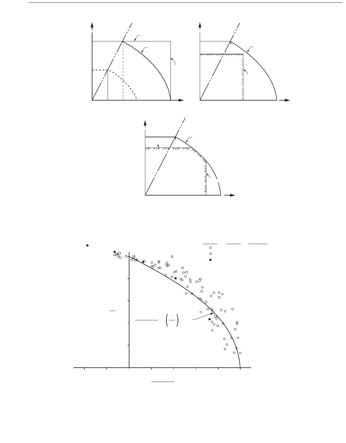
The formulas given in Section 3.2.5 to compute the elastic
buckling stress represent 0.8 times the theoretical stress
obtained using classical small deflection theory. The implied
20 percent reduction factor (α = 0.80), included in the coeffi-
cient C
h
, accounts for the effect of geometric imperfections
due to fabrication. All available test data indicate that this is
sufficiently conservative for cylinders fabricated within API
Spec 2B out-of-roundness tolerances. For cylinders with
greater out-of-roundness values, local buckling test results
on steel cylinders suggest a lower bound reduction factor
given by:
α = 1.0 – 1.2 (C3.2.5-1)
This value of α was used to normalize the available results
with respect to α = 0.80 (for one percent out-of-roundness),
before plotting the results in Figures C3.2.5-1 and C3.2.5-2
for comparison with the design equations for F
he
.
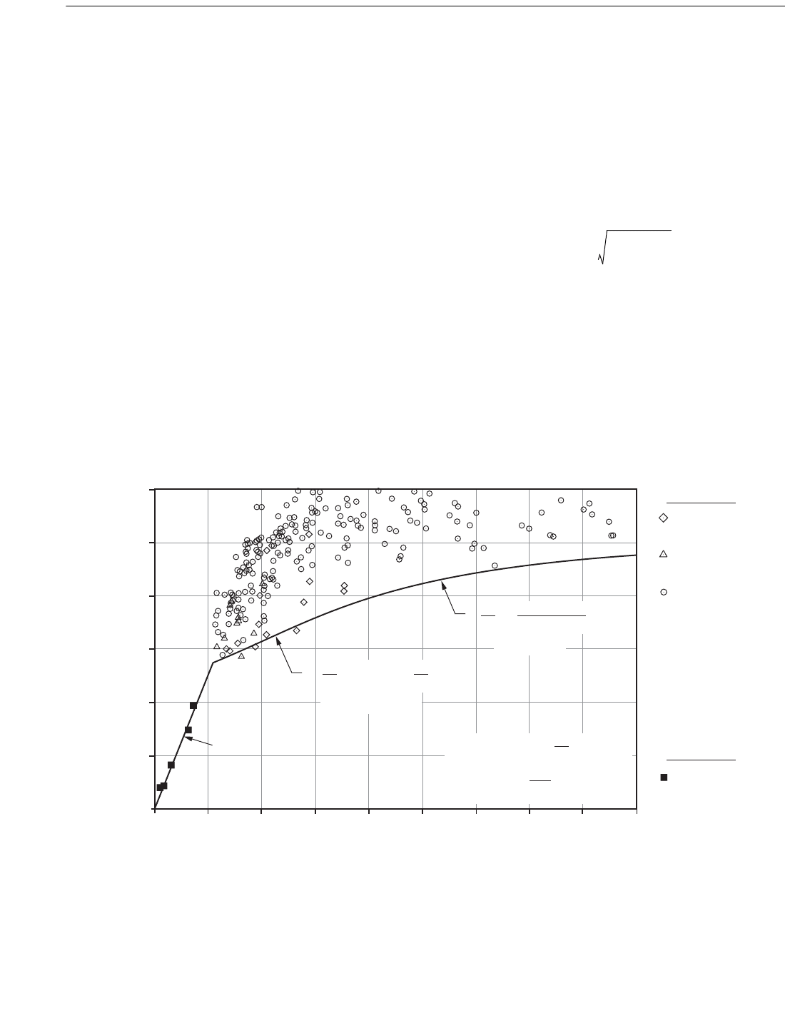
When the elastic hoop buckling stress exceeds 0.55 F
y
, it is
necessary to apply a plasticity reduction factor to account for
the effect of inelasticity and residual stresses. The plasticity
reduction factors given in Eq. 3.2.5-6 to compute the inelastic
buckling stress F
he
represent a reasonable lower bound for
the available test data shown in Figure C3.2.5-3.
D
max
D
min
–
0.01D
---------------------------
Figure C3.2.5-3—Comparison of Test Data with Design Equations for Ring Buckling and
Inelastic Local Buckling of Cylinders Under Hydrostatic Pressure
(Elastic Local Buckling Data Shown in Figures C3.2.5-1 and C3.2.5-2 are Omitted for Clarity)
0.00
0.20
0.40
0.60
0.80
1.00
1.20
0.00
0.50
1.00 1.50 2.00 2.50 3.00 3.50 4.00 4.50
F
he
/F
y
F
hc
/F
he
F
hc
/F
y
Fabricated
(rolled plate)
Fabricated
(sheet material)
Manufactured pipe
Fabricated
(rolled plate)
= 0.45 + 0.18
F
hc
F
y
F
he
F
y
(0.55 < F
he
/F
y
1.6)
=
F
hc
F
y
t
D
1.31
1.15 + (F
y
/F
he
)
(F
he
/F
y
> 1.6)
(Local) F
he
= 2 CE Eq. 3.2.5-4
8EI
c
D
2
L
t
(Ring) F
he
= Eq. 3.2.5-7
Local Buckling
Ring Buckling
Copyright American Petroleum Institute
Provided by IHS under license with API
Licensee=Indonesia location/5940240008
Not for Resale, 10/22/2008 00:07:12 MDT
--`,,```,,,`,,,,,,,,,,,,,,`,``,`-`-`,,`,,`,`,,`---
170 API RECOMMENDED PRACTICE 2A-WSD
The formula given for determining the moment of inertia
of stiffening rings, Eq. 3.2.5-7, provides sufficient strength to
resist collapse even after the shell has buckled between stiff-
eners. It is assumed that the shell offers no support after buck-
ling and transfers all its load to the effective stiffener section.
The stiffening ring is designed as an isolated ring that buckles
into two waves (n=2) at a collapse pressure 20 percent higher
than the strength of the shell.
Test results for steel cylinders indicate that a geometric
imperfection reduction factor given by:
α = 1.0 – 0.2 (C3.2.5-2)
is applicable for general instability failures of cylinders with
initial out-of-roundness values exceeding one percent. A
value of α = 0.80 is appropriate for out-of-roundness values
less than one percent. These α values were used to normalize
the general instability test results included in Figure C3.2.5-3
to correspond to a one percent out-of-roundness basis.
Note that when the geometric parameter M exceeds 1.6
D/t, a ring-stiffened cylinder behaves essentially like an
unstiffened cylinder of infinite length. In order to be bene-
ficial, therefore, ring stiffeners should be spaced such that
M < 1.6 D/t.
References
(1) Guide to Stability Design Criteria for Metal Structures,
Structural Stability Research Council, Fourth Edition, John
Wiley & Sons, 1988.
(2) Miller, C. D., Buckling of Axially Compressed Cylinders,
Journal of the Structural Division, ASCE, March 1977.
(3) Boardman, H. C., Stresses at Junctions of Two Right
Cone Frustums with a Common Axis, the Water Tower, Chi-
cago Bridge and Iron Co., March 1948.
(4) Johns, D. J., Local Circumferential Buckling of Thin Cir-
cular Cylindrical Shells, Collected Papers on Instability of
Shell Structures, NASA TN D-1510, December 1962.
(5) Sherman, D. R., Bending Capacity of Fabricated Pipe at
Fixed Ends, Report to API, University of Wisconsin-Milwau-
kee, December 1985.
(6) Stephens, M. J., Kulak, G. L., and Montgomery, C. J.,
Local Buckling of Thin Walled Tubular Steel Members, Struc-
tural Engineering Report No. 103, University of Alberta,
Edmonton, Canada, February 1982.
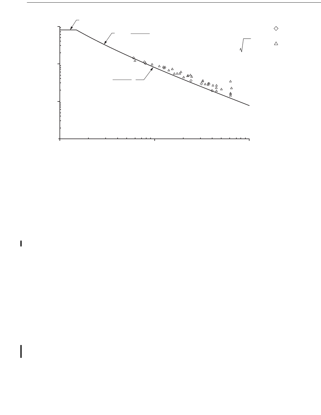
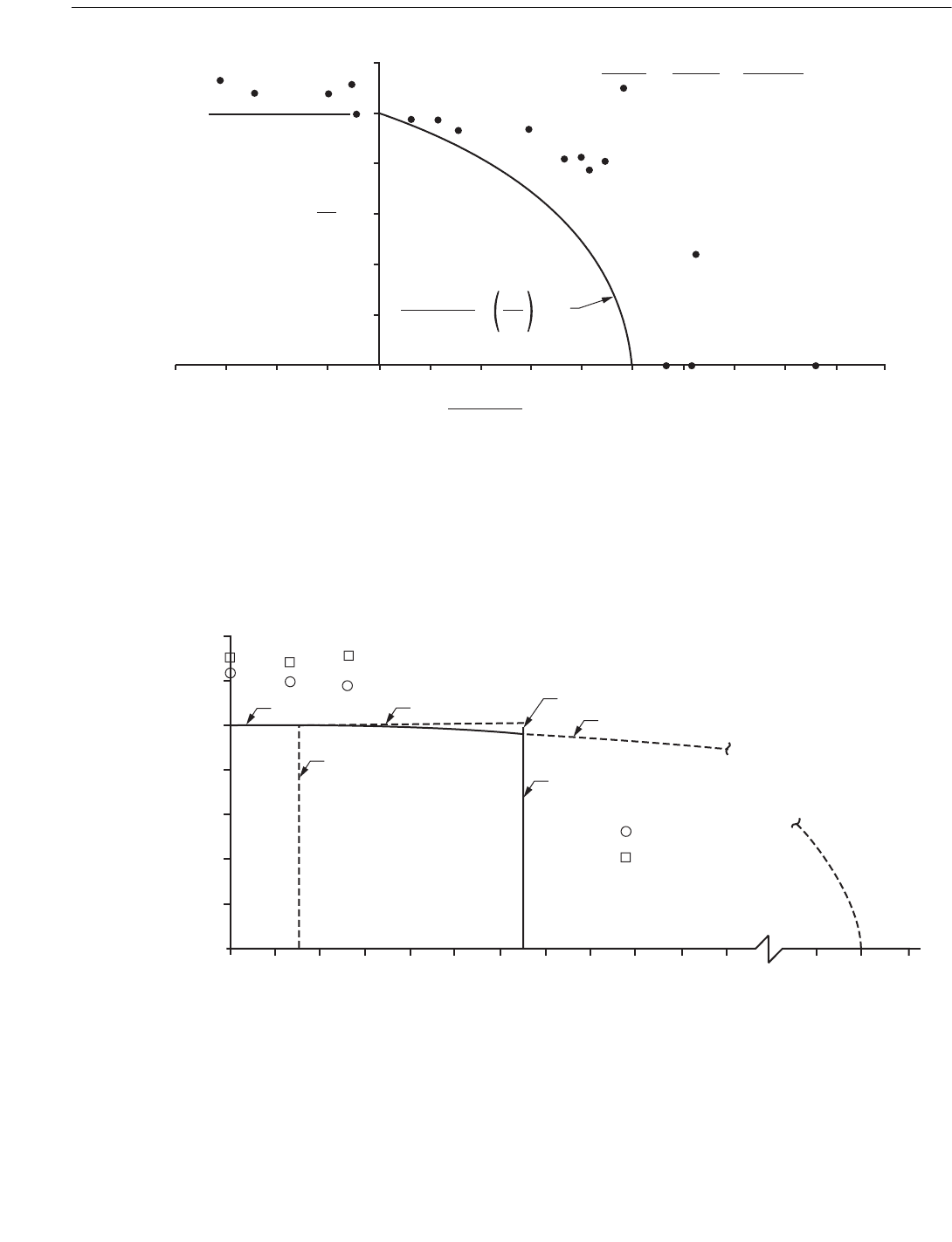
Figure C3.2.5-1—Comparison of Test Data with Elastic Design Equations for Local Buckling of
Cylinders Under Hydrostatic Pressure (M > 0.825 D/t)
5
0.2
0.4
0.6
0.8
1.0
1.2
0
1.0
1.5 2.0 2.5
M / (D/t)
3.0 3.5 4.0 4.5
C x (D/t)
t
D
0.21 (D/t)
3
M
4
+
C = 0.44
(0.825 D/t M < 1.6 D/t)
C = 0.44 t/D
(M 1.6 D/t)
Fabricated (rolled plate)
Manufactured pipe
C
F
he
2E
-------
D
t
----=
M
L
D
----
2D
t
-------=
D
max
D
min
–
0.01D
---------------------------
Copyright American Petroleum Institute
Provided by IHS under license with API
Licensee=Indonesia location/5940240008
Not for Resale, 10/22/2008 00:07:12 MDT
--`,,```,,,`,,,,,,,,,,,,,,`,``,`-`-`,,`,,`,`,,`---
RECOMMENDED PRACTICE FOR PLANNING, DESIGNING AND CONSTRUCTING FIXED OFFSHORE PLATFORMS—WORKING STRESS DESIGN 171
C3.3 COMBINED STRESSES FOR STEEL
CYLINDRICAL MEMBERS
Introduction. This section of the commentary describes the
background of the design recommendations in Section 3.3,
which covers the buckling of unstiffened and ring-stiffened
cylinders under combined axial, bending, and hydrostatic
external pressure loads.
C3.3.3 Axial Tension and Hydrostatic Pressure
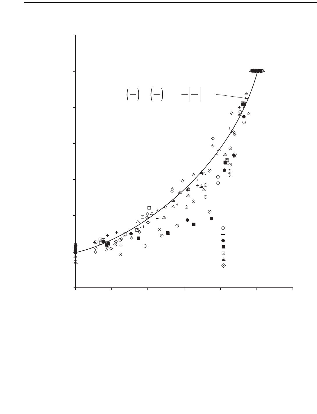
The interaction formula recommended to check axial ten-
sion and hydrostatic pressure interaction is based on the Bel-
trami and Haigh maximum total energy theory, with the
critical hydrostatic buckling stress substituted for the yield
stress and Poisson’s ratio set equal to 0.3. The Beltrami and
Haigh failure theory reduces to the Hencky-von Mises distor-
tion energy theory with Poisson’s ratio equal to 0.5. A com-
parison with available test data, shown in Figure C3.3.3-1,
confirms that the recommended interaction formula is appro-
priate for D/t values typically used for offshore platform
members. The test data that fall inside the ellipse correspond
to stretch failures and tests with very low D/t values.
C3.3.4 Axial Compression and Hydrostatic
Pressure
The combination of hydrostatic pressure and axial load
may produce a different critical buckling stress than either of
these load systems acting independently. Figure C3.3.3-2
illustrates the recommended interaction equations for various
possible stress conditions. These interaction equations imply
that no interaction occurs if the axial stress is less than one-
half the allowable hoop stress.
The recommended interaction equations have been
checked against the results of available tests and found to
give conservative results, as shown in Figures C3.3.3-3,
C3.3.3-4, and C3.3.3-5. Figure C3.3.3-3 shows the results of
elastic buckling tests on mylar, plexiglass, and fabricated
steel cylinders, while Figure C3.3.3-4 shows the results of
fabricated steel cylinders alone. In Figure C3.3.3-3 the test
results are compared with the recommended equation for
elastic interaction, Eq. 3.3.4-3 using F
xe
and F
he
values deter-
mined from the tests. This comparison validates the form of
Eq. 3.3.4-3. In Figure 3.3.3-4, the fabricated steel cylinder
test results are compared with Eq. 3.3.4-3, using F
xe
and F
he
values computed from the design equations in Section 3.2.
This confirms that Eq. 3.3.4-3 is conservative. In Figure
C3.3.3-5, the recommended interaction equations are com-
pared with the results of test data for unstiffened steel pipe
with an elastic hydrostatic buckling stress and an inelastic
axial buckling stress. This comparison demonstrates the
validity of the recommended interaction equations for com-
bined elastic and inelastic behavior.
References
(1) Weingarten, V. I., Morgan, E. J., and Seide, P., Final
Report on Development of Design Criteria for Elastic Stabil-
ity of Thin Shelled Structures, Space Technology Laboratories
Report STL-TR-60-0000-19425, December 1960.
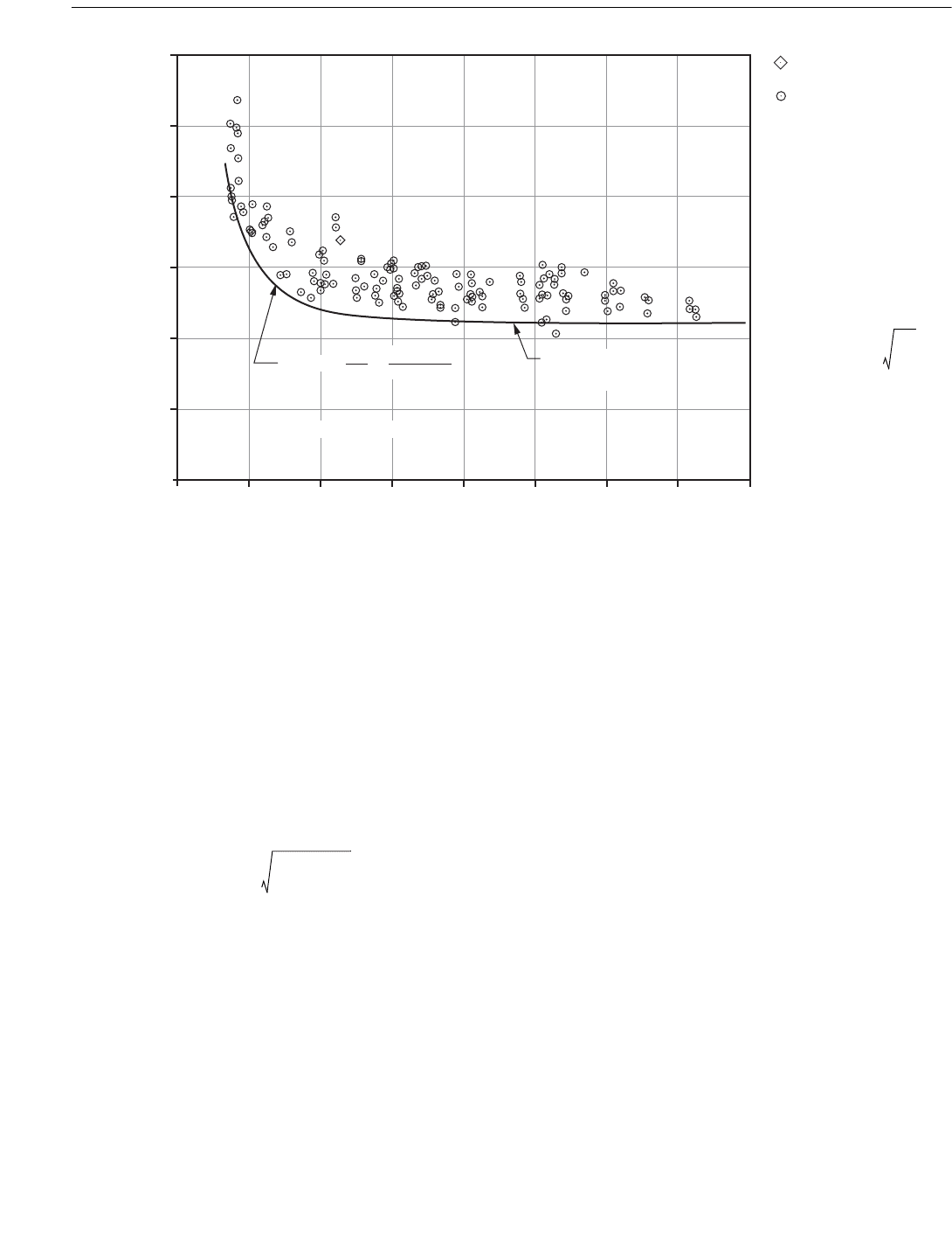
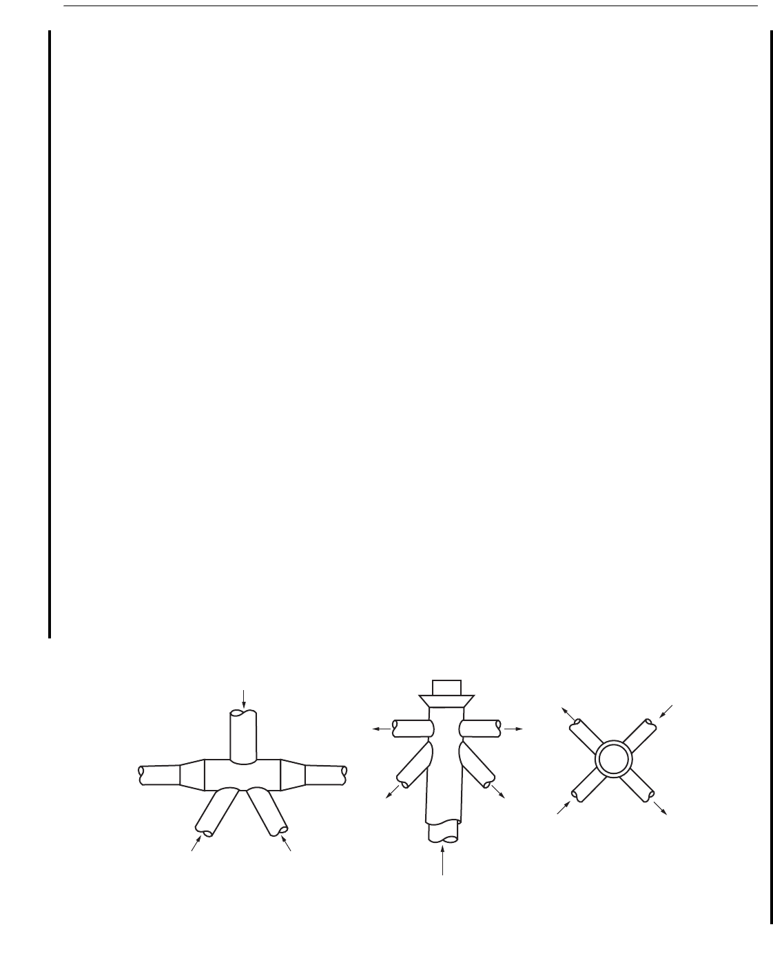
Figure C3.2.5-2—Comparison of Test Data with Elastic Design Equations for Local Buckling of
Cylinders Under Hydrostatic Pressure (M < 0.825 D/t)
0
0.01
0.1
C
1.00
0.001
10
M
100
C =
0.755
M – 0.559
C = 0.8 (M < 1.5)
(1.5 M < 3.5)
C =
0.736
M – 0.636
(3.5 M < 0.825 D/t)
Fabricated
(rolled plate)
Fabricated
(sheet material)
C
F
he
2E
-------
D
t
----=
M
L
D
----
2D
t
-------=
07
07
Copyright American Petroleum Institute
Provided by IHS under license with API
Licensee=Indonesia location/5940240008
Not for Resale, 10/22/2008 00:07:12 MDT
--`,,```,,,`,,,,,,,,,,,,,,`,``,`-`-`,,`,,`,`,,`---
172 API RECOMMENDED PRACTICE 2A-WSD
(2) Mungan, I., Buckling Stress States of Cylindrical Shells,
Journal of Structural Division, ASCE, Vol. 100. No. ST 11,
November 1974, pp. 2289-2306.
(3) Miller, C. D., Summary of Buckling Tests on Fabricated
Steel Cylindrical Shells in USA, Paper 17, Presented at Buck-
ling of Shells in Offshore Structures Symposium, Imperial
College of Science and Technology, London, April 1981.
(4) Stuiver, W., and Tomalin, P. F., The Failure of Tubes
Under Combined External Pressure and Axial Loads, SESA
Proceedings, Vol. XZ12, pp. 39-48.
Figure C3.3.3-1—Comparison of Test Data with Interaction Equation for Cylinders Under Combined Axial Tension
and Hydrostatic Pressure (F
hc
Determined from Tests)
0.00
–1.00
–0.80
–0.60
–0.40
–0.20
0.00
0.20
–1.20
0.20
F
hc
(Test) < F
y
0.40 0.60 0.80 1.00 1.20
f
x
/F
y
f
h
/F
hc
(Test)
– E&M SAE4140 D/t = 21.7
– E&M SAE1045 D/t = 21.7
– S&T D/t = 23.45
– S&T D/t = 27.03
– E&M SAE4130X D/t = 18.2
– E&M SAE4140 D/t = 17.3
– E&M SAE1045 D/t = 17.3
f
x
F
y
f
x
F
y
f
h
F
hc
2
f
h
F
hc
2
+ + 2 n
where n = 0.3
= 1.0
Copyright American Petroleum Institute
Provided by IHS under license with API
Licensee=Indonesia location/5940240008
Not for Resale, 10/22/2008 00:07:12 MDT
--`,,```,,,`,,,,,,,,,,,,,,`,``,`-`-`,,`,,`,`,,`---
RECOMMENDED PRACTICE FOR PLANNING, DESIGNING AND CONSTRUCTING FIXED OFFSHORE PLATFORMS—WORKING STRESS DESIGN 173
Figure C3.3.3-2—Comparison of Interaction Equations for Various Stress Conditions for Cylinders
Under Combined Axial Compressive Load and Hydrostatic Pressure
Figure C3.3.3-3—Comparison of Test Data with Elastic Interaction Curve for Cylinders
Under Combined Axial Compressive Load and Hydrostatic Pressure
(F
xe
and F
he
are Determined from Tests)
(a) Elastic Buckling
f
h
f
x
= 0.5 f
h
Eq. 3.3.4-2
Eq. 3.3.4-3
Eq. 3.3.4-1
f
hc
= f
he
f
ha
0.5 f
ha
0.5 f
he
f
aa
f
xc
= f
xe
f
x
(b) Yield Type Failure
f
h
f
x
= 0.5 f
h
Eq. 3.3.4-2
Eq. 3.3.4-3
Eq. 3.3.4-1
f
he
f
hc
f
x
f
xe
f
x
(c) Elastic and Yield Type
Combined
f
h
f
x
= 0.5 f
h
Eq. 3.3.4-2
Eq. 3.3.4-3
f
he
f
hc
f
xc
f
xe
f
x
Eq. 3.3.4-1
0.2
0.4
0.6
0.8
1.0
Ð0.4
Ð0.2 0 0.2 0.4 0.6 0.8 1.0
Mylar 1
Plexiglass 2
Steel (fab.) 3
f
x
Ð 0.5 F
he
F
xe
Ð 0.5 F
he
f
x
Ð 0.5 F
he
F
xe
Ð 0.5 F
he
f
h
F
he
f
h
F
he
2
+ = 1.0
Symbol Material Reference
Copyright American Petroleum Institute
Provided by IHS under license with API
Licensee=Indonesia location/5940240008
Not for Resale, 10/22/2008 00:07:12 MDT
No reproduction or networking permitted without license from IHS
174 API RECOMMENDED PRACTICE 2A-WSD
Figure C3.3.3-4—Comparison of Test Data on Fabricated Cylinders with Elastic Interaction Curve for Cylinders
Under Combined Axial Load and Hydrostatic Pressure
(F
xe
and F
he
are Determined from Recommended Design Equations)
Figure C3.3.3-5—Comparison of Test Data with Interaction Equations for Cylinders
Under Combined Axial Compressive Load and Hydrostatic Pressure
(Combination Elastic and Yield Type Failures)
0.2
0.4
0.6
0.8
1.0
1.2
Ð0.4
Ð0.6Ð0.8 Ð0.2 0 0.2 0.4 0.6 0.8 1.0 1.2 1.4 1.6 1.8 2.0
Steel (fab.) 3
f
x
Ð 0.5 F
he
F
xe
Ð 0.5 F
he
f
x
Ð 0.5 F
he
F
xe
Ð 0.5 F
he
f
h
F
he
f
h
F
he
2
+ = 1.0
Symbol Material Reference
0
1.4
1.2
0.8
1.0
0.6
0.2
0.4
0
0.1 1.00.2
F
hc
= F
he
f
x
= 0.5 F
he
F
xc
= F
y
f
x
/ F
xe
f
h
/ F
he
Eq. 3.3.4-2
Eq. 3.3.4-3
Eq. 3.3.4-1
Ref. (4)
D/ = 22.5
D/ = 26.0
E = 26,000 ksi
F
y
= 79 ksi
Copyright American Petroleum Institute
Provided by IHS under license with API
Licensee=Indonesia location/5940240008
Not for Resale, 10/22/2008 00:07:12 MDT
--`,,```,,,`,,,,,,,,,,,,,,`,``,`-`-`,,`,,`,`,,`---

RECOMMENDED PRACTICE FOR PLANNING, DESIGNING AND CONSTRUCTING FIXED OFFSHORE PLATFORMS—WORKING STRESS DESIGN 175
C4 COMMENTARY ON STRENGTH OF
TUBULAR JOINTS
C4.1 APPLICATION
The provisions of Section 4 are wide-ranging and are
intended to provide the practicing engineer with as much
guidance as is currently available in this field, for the range of
joint configurations, geometries and load cases that exist in
practice. Although a substantial effort has been expended to
capture the present day technology, it is recognized that in
some instances the designer may have to use test data and
analytical techniques as a basis for design. Ref. 1 permits the
designer to select an appropriate reduction factor for joint
strength to account for a small number of data. Where the
basis for the calculation of joint strength or calibration of
numerical techniques to suitable test data is poor, a reduction
factor of 0.7 has been known to be applied.
It is appropriate to summarize the historical development
of the API RP 2A-WSD provisions and the background to
the most recent major updates as incorporated into this sup-
plement to the 21
st
edition. In the 3rd edition of API RP 2A-
WSD, issued in 1972, some simple recommendations were
introduced based on punching shear principles (Ref. 3). In
the 4
th
edition, factors were introduced to allow for the pres-
ence of load in the chord and the brace-to-chord diameter
ratio (β). In the 9
th
edition, issued in 1977, differentiation
was introduced in the allowable stress formulations for the
joint and loading configuration i.e., T/Y, X and K.
Much work was done over the period 1977 to 1983, includ-
ing large-scale load tests to failure, to improve the under-
standing and prediction of joint behavior. This work
culminated in the issue of the 14
th
edition of API RP 2A-
WSD, in which the punching shear stress formulations were
considerably modified and included a more realistic expres-
sion to account for the effect of chord loads as well as provid-
ing an interaction equation for the combined effect of brace
axial and bending stresses. Also introduced in the 14
th
edition
was the alternative nominal load approach, which gives
equivalent results to the punching shear method. Some of the
background to this step change in approach can be found in
Ref. 4. The guidance then essentially remained unchanged for
all editions up to the 21st, although further recommendations
were added on load transfer through the chord in the 20
th
edi-
tion (1993).
Regardless of API RP 2A-WSD stability, much further
knowledge, including both experimental data and numerical
studies, has been gained on the behavior of joints since the
14
th
edition was issued. Over the period 1994 to 1996 MSL
Engineering, under the auspices of a joint industry project,
undertook an update to the tubular joint database and guid-
ance (Refs. 5 to 7). This work and more recent studies, nota-
bly by API/EWI and the University of Illinois, have formed
the basis of the tubular joint strength provisions of ISO (Ref.
8). The ISO drafting committee took, as a starting point for
drafting, the relevant provisions from API RP 2A-LRFD 1
st
edition (similar to API RP 2A-WSD 20
th
edition) because
ISO is in LRFD format. However, the API RP 2A-WSD pro-
visions were greatly modified during the drafting process to
take account of the greater knowledge.
For the purposes of this supplement to the 21
st
edition of
API RP 2A-WSD, the draft ISO provisions, in turn, have
been used as a starting basis. Additional studies, not available
at the time of the preparation of the draft ISO guidance have
been incorporated into this supplement to the 21
st
edition of
API RP 2A-WSD. The major updates between the 21
st
edi-
tion and this supplement to the 21
st
edition are detailed in the
following subsections but, in summary, involve: a relaxation
of the 2/3 limit on tensile strength, additional guidance on
detailing practice, removal of the punching shear approach,
new Q
u
and Q
f
formulations, and a change in the form of the
brace load interaction equation.
C4.2 DESIGN CONSIDERATIONS
C4.2.1 Materials
All of the empirical strength equations have been based
upon measured yield. Very few test results have indicated
unexpected low capacity due to substandard material proper-
ties. However, it is recognized that some limits are implied by
the database.
One important change resulting from the MSL work (Refs.
5 to 7) concerns new steels with high yield-to-tensile strength
ratios. Previous editions of API RP 2A-WSD did not allow
the designer to assume more than a value of 2/3. In other
words, if the ratio exceeded this limit, the designer had to
downgrade the assumed chord yield level to 66 percent of
tensile strength. The MSL work found that the database justi-
fied a limit of 0.8 for joints with a chord yield of up to at least
72 ksi (500 MPa).
The material property range is limited to F
y
≤ 72 ksi (500
MPa). Historically, there has been a concern that the strength
of joints with chord yield stresses in excess of 72 ksi (500
MPa) may not increase in proportion to the yield stress. The
concern relates to the possibility that higher yield strength
may be obtained at the expense of lower ductility and lower
strain-hardening capacity, thereby compromising the post-
yield reserve strength on which the design criteria rely. This
matter is discussed in Ref. 9. A re-evaluation of the test
results reported therein has revealed that use of the limiting
yield-to-tensile strength ratio of 0.8 appears to be adequate to
permit the capacity equations to be used for joints with 72 ksi
(500 MPa) < F
y
≤ 115 ksi (800 MPa), provided adequate duc-
tility can be demonstrated in both the heat affected zone and
parent material. However, the test data reported in Ref. 9 are
limited to a small number of joint types and loading modes
(i.e., 11 joints).
05
05
07
Copyright American Petroleum Institute
Provided by IHS under license with API
Licensee=Indonesia location/5940240008
Not for Resale, 10/22/2008 00:07:12 MDT
--`,,```,,,`,,,,,,,,,,,,,,`,``,`-`-`,,`,,`,`,,`---

176 API RECOMMENDED PRACTICE 2A-WSD
A recently completed joint industry project (Ref. 10) inves-
tigated the static strength of high strength steel X joints. The
joint industry project involved the testing of four compression
joints (two at a nominal yield strength of 355 MPa and one
each at 500 MPa and 700 MPa) and three tension joints (one
each at nominal yield strength of 355 MPa, 500 MPa and
700 MPa). The findings presented in Ref. 10 indicate that all
the joints performed satisfactorily in the tests in terms of
strength and ductility, confirming the practicality of using
higher strength steels. These data indicate that a yield-to-ten-
sile strength ratio of 0.8 can be used to estimate the ultimate
compression and tension capabilities of the joints. However,
for the tension loaded joints in which cracking prior to reach-
ing the ultimate capacities was observed, no detailed assess-
ments were presented.
Beyond 800 MPa, indicative capacity estimates may be
obtained through use of a yield stress of 800 MPa or 0.8 times
the tensile strength, whichever is the lesser. Given the lack of
data and information in this area, this approach should be
considered to be only indicative.
C4.2.2 Design Loads and Joint Flexibility
Given present-day computer power and software packages,
it is generally recommended that working point offsets be
defined in the analysis model to capture secondary moments.
Optionally, rigid offsets from the working points on the chord
centerline to the chord surface can also be defined. Such off-
sets can be used to reduce the bending moments from nodal
values to those at the chord surface (the moment capacity
equations were established for chord surface moments).
Historically, designers of offshore jacket structures have
usually made the assumption that the joints are rigid and that
the frame can be modeled with members extending to work-
ing points at chord centerlines. However, it has long been rec-
ognized that the linear elastic flexibility of tubular joints may
be significant at locations such as skirt pile bracing and in
computing fatigue life estimates for secondary connections.
For conductor framing connections, fatigue life estimates can
be substantially larger when linear elastic flexibilities are
included in the analyses, because the member lengths are
short and member flexibility tends to be less than joint flexi-
bility. From a system ultimate strength standpoint, full, non-
linear, load-deformation curves for joints may be required in
pushover analyses, especially where joint failures are
expected to participate in the sequence of events leading to
system collapse. Such analyses are common in the mainte-
nance of infrastructure and life extension studies of existing
facilities.
In 1993, Buitrago et al. (Ref. 11) published a robust set of
equations for linear elastic flexibility/stiffness of simple tubu-
lar joints. Although a number of other sets of formulations are
available in the literature, Buitrago’s formulations are consid-
ered to be more wide-ranging, have better physical meaning,
compare better with experimental data and are simpler to use
manually and computationally.
In Ref. 6, the technology pertaining to linear elastic flexi-
bility was extended through analyses of the updated database,
to establish a range of closed-form expressions, which permit
the designer to create non-linear load-deformation (P
δ
or M
θ
)
curves in both the loading and unloading regimes for simple
joints across the practical range of load cases and geometries.
The full non-linear expressions will see application primarily
in pushover analyses, especially where joint failures are pos-
tulated to influence to the peak failure load.
Ref. 12 reports on a pilot study to assess the effect of
hydrostatic pressure on tubular joint capacity. DT joints are
studied, and the results indicate that capacity may be reduced
by up to 30%, depending on geometry, brace load case and
hydrostatic pressure magnitudes. Apart from Ref. 12, no
other studies in this area have been identified. Hydrostatic
pressure effects can be significant, especially for deepwater
structures, and the designer is referred to Ref. 12 when con-
sidering these effects. In many instances, members are pur-
posefully flooded to avoid hydrostatic pressure effects.
C4.2.3 Minimum Capacity
API has a broad minimum capacity requirement that
equate to 50 percent of the capacity of the incoming brace.
For earthquake loading, the requirement is essentially 100
percent of the brace capacity. Aside from earthquake regions,
the 50 percent capacity sometimes dominated secondary joint
design (Ref. 13) and took precedence on primary joints. In
general, joint failure prior to member reaching allowable
stress is undesirable, due to uncertainty in failure behavior
and the effect on surrounding structure.
However, joint yielding prior to member buckling may be
a more benign failure mode. Also, where secondary branch
members have been strengthened for localized loadings, cor-
rosion allowance, or section availability, 50% rule need not
apply.
To address the relative reliability of joints and members,
and to ensure that the members fail first, it has been suggested
that the utilization factor of critical joints be limited to 85%
that of its branch members. The designer may wish to deter-
mine critical joints for this minimum capacity imposition, e.g.
joints that influence the reserve strength of the structure in a
design load event (wave load, earthquake, etc.) or joints that
influence the response of the structure when subjected to
accidental loads.
C4.2.4 Joint Classification
API has long recognized that joint classification should be
based on axial load pattern as well as joint configuration. In
principle, classification is an issue for both simple and com-
plex joint configurations and is relevant to both fatigue and
strength assessments. However, the classifications are not
always the same as they can vary with wave direction and
period. Classifications, and subsequent code checks, for
strength should not be based on only a consideration of the
wave loading at maximum shear or overturning moment. In
05
05
Copyright American Petroleum Institute
Provided by IHS under license with API
Licensee=Indonesia location/5940240008
Not for Resale, 10/22/2008 00:07:12 MDT
No reproduction or networking permitted without license from IHS
RECOMMENDED PRACTICE FOR PLANNING, DESIGNING AND CONSTRUCTING FIXED OFFSHORE PLATFORMS—WORKING STRESS DESIGN 177
general, classification for wave loading is best established by
stepping the wave through the structure.
Several schemes for automating the classification process
have evolved over the years. None is unique. In all of them,
member ends belonging to a particular joint are identified and
the geometric information is catalogued. Member ends lying
in a common plane and on the same side of the joint are iden-
tified and the gap between them is computed. Each member
end is evaluated for each axial load case. Classification may
change from load case to load case and is often different for
each member end at a given joint. Mixed classifications gen-
erally occur.
In the logic of the recommended classification scheme,
members whose axial load component perpendicular to the
chord is essentially balanced by axial loads in other members
on the same side of the joint are treated as K joints. Examples
(a), (d), (e) and (g) in Figure 4.2-1 of Section 4.2.4 are such
cases, as are the lower braces in examples (c) and (h). Mem-
bers whose perpendicular load components are reacted across
the chord are treated as X joints, as in example (f), even
though the geometric appearance may be K. Finally, mem-
bers whose perpendicular loads are neither K nor X but are
reacted by beam shear in the chord are treated as Y joints, as
in example (b). In some classification schemes, the hierarchy
is K followed by Y, with X being the default.
There are instances where the axial load of a given brace is
within ±10% of being purely one of the standard joint types
(i.e., all Y, X, or K). In that case it is permissible to classify
the brace end as totally of that joint type and no interpolation
is required. However, many joints have braces that are not
clearly of a given type. In other words, the loading conditions
are complex in the sense that an individual member axial load
must be divided into portions that are treated as K, Y and X.
Examples (c) and (h) in Figure 4.2-1 of Section 4.2.4 contain
member ends with mixed classifications.
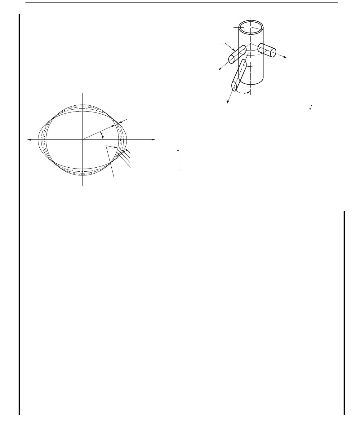
The classification scheme does not quantitatively address
multiplanar connections, even though offshore jackets are
space frames, not planar trusses. Furthermore, the scheme
does not recognize that several braces in a given plane may
simultaneously contribute to ovalization of the chord, as for
launch trusses and other examples in Figure C4.2-1. Such
load cases can produce a more adverse load condition than is
recognized in the classification scheme. In cases such as those
in Figure C4.2-1, it is conservative to first find the sum of the
perpendicular load components that are passed through the
chord section and assume that the capacity is the minimum of
any one of the brace-chord intersections when acting as a X
joint. To reduce the conservatism, the designer may resort to
general collapse calculations or finite element analysis.
An alternative approach to joint classification is to use the
ovalizing parameter α from Annex L of AWS D1.1-2002
(Ref. 14). See Figure C4.2-2. The attraction of the α-based
classification in AWS D1.1 is that it does not require the
designer to make decisions concerning classification. In a
general sense, it encompasses the recommended simple joint
classification scheme, and provides a viable design methodol-
ogy for adverse loading cases (Figure C4.2-1) and multipla-
nar joints, for which it was originally derived. Typical values
of α are: around 1.0 for balanced K-joints, around 1.7 for Y-
joints, and around 2.4 for X-joints. For multi-planar X-X
joints, α can vary from 1.0 to 3.8, depending on the load pat-
tern; appropriateness of this has been verified by inelastic
finite element analysis (Ref. 67), However, the severity of
ovalizing is overstated when diameter ratio β is above 0.9,
and understated for K-K joints in delta trusses. Further, AWS
does not properly incorporate the effect of transverse gap or
address tension failures in the same manner as in Section 4.3.
A recently completed joint industry project (Ref. 15) has gen-
erated a considerable database of FE results for multi-planar,
axially loaded joints having no overlapped braces. Refined
expressions are given for the ovalizing parameter α that may
be used within the AWS D1.1 approach.
05
05
07
Figure C4.2-1—Adverse Load Patterns with α Up to 3.8 (a) False Leg Termination,
(b) Skirt Pile Bracing, (c) Hub Connection
(a)
(b) (c)
Copyright American Petroleum Institute
Provided by IHS under license with API
Licensee=Indonesia location/5940240008
Not for Resale, 10/22/2008 00:07:12 MDT
--`,,```,,,`,,,,,,,,,,,,,,`,``,`-`-`,,`,,`,`,,`---
178 API RECOMMENDED PRACTICE 2A-WSD
Additional provisions specific to axially loaded, multipla-
nar X, Y, and K joints can be found in the CIDECT Design
Guide (Ref. 16). More contemporary information on multi-
planar Y and K joints is available in Refs. 17 to 20. However,
the designer should be aware that none of these guidances are
especially robust. There are general restrictions as to loading
pattern as well as joint configuration.
Effect of Classification on Basic Capacity. Unlike pre-
vious API practice where interpolation of Q
u
was adequate
for axially loaded braces with mixed classification, interpola-
tion based on a weighted average of P
a
is required since Q
f
also varies with axial load classification. Taking Figure 4.2-
1(h) of Section 4.2.4 as an example, the diagonal brace has a
50% K and 50% X classification. In this case, P
a
is calculated
separately for K classification and X classification. In the cal-
culation for X classification, capacity downgrading (if any) in
accordance with Section 4.3.5 requires consideration. The
joint characteristic axial capacity can thereafter be calculated
as follows:
P
a
= 0.5 (P
a
)
K
+ 0.5 (P
a
)
X
where
P
a
= The allowable axial joint capacity,
(P
a
)
K
= The allowable axial joint capacity for K classi-
fication,
(P
a
)
X
= The allowable axial joint capacity for X classi-
fication.
In the interaction equation in Section 4.3.6, it can be seen
that the axial term is thus computed as:
Where k, x, and y are the proportions of the classification
(Note k + x + y = 1.0).
The above principle can also be extended to address the
case of the middle brace of a KT joint, which may have K
action with both adjacent braces. In this instance (Pa)
K
would
be computed as the weighted average of the (Pa)
K
individual
values.
Other possibilities exist for combining the effect of mixed
classifications. These possibilities are addressed in Ref. 20,
where it is concluded that a linear term in the interaction
equation is also viable:
C4.2.5 Detailing Practice
The previous API guidelines in the 21
st
edition have been
changed in several important ways. The can and stub length
Figure C4.2-2—Computed α (a) Equation, (b) Definitions, (c) Influence Surface
T
I
I
cos 2 I
Position of reference brace
(a)
(b)
(c)
T
R
P
P
Tension is
Positive
Reference brace for
which D applies
P
L
100% @ same plane
62% @ 0/2 away
38% @ 0 away
15% @ 20 away
No influence at great distance
For
J – 12
Influence of
braces in other
positions around
circumference
α 1.0 0.7
P sin θ cos2 φ exp
Z
0.6γ
-----------
–
all braces at a joint
∑
P sin θ[]reference brace for which α applies
-----------------------------------------------------------------------------------------------------------+=
07
05
α 1.0>
Z
L
RT
------------=
γ
R
t
----=
P
P
a
-----
P
kP
a
()
K
xP
a
()
X
yP
a
()
y
++
-----------------------------------------------------------=
05
P
P
a
-----
kP
P
a
()
K
-------------
xP
P
a
()
X
------------
yP
P
a
()
Y
------------++=
Copyright American Petroleum Institute
Provided by IHS under license with API
Licensee=Indonesia location/5940240008
Not for Resale, 10/22/2008 00:07:12 MDT
No reproduction or networking permitted without license from IHS