Astakhov V. Tribology of Metal Cutting
Подождите немного. Документ загружается.


Tribology of the Tool–Chip and Tool–Workpiece Interfaces 197
The maximum temperature at the tool rake face θ
fr−max
is calculated as
θ
fr−max
= θ
O
(
1 + ψ
M
)
(3.99)
The temperature at point C (Fig. 3.21(a)) where the chip separates with the tool rake
face is calculated as
θ
fr−C
= θ
O
(
1 + 0.66ψ
M
)
(3.100)
An example of the calculations of the temperature distribution over the tool rake face is
shown in Fig. 3.47(b).
The cutting temperature in the sense of definition is given in Section 3.4.1 and is
calculated as
θ =
⎛
⎜
⎝
0.95τ
c
Pe
0.375
E
0.055
erf
0.4
PeBr
4
C
p−w
ρ
w
Br
0.625
F
0.15
θ
D
0.045
(
1 − sin γ
)
0.65
sin
0.03
α
⎞
⎟
⎠
(3.101)
Analysis of Eq. (3.101) arrives at the following conclusions:
• As the cutting speed (ν) and uncut chip thickness (t
1
) increase (so does Pe = νt
1
/w
w
as per Eq. (2.35)), the cutting temperature increases. As such, t
1
has a smaller
influence as it is found in numbers E and D.
• The cutting temperature grows with the strength of the work material. However, its
power is less than 1 because it affects CCR and thus Br.
• With increasing the thermoconductivity (k
w
) and specific heat of the work material
C
p
ρ
w
and thermoconductivity of the tool material (k
ct
) the cutting tempera-
ture decreases. If it is assumed that Br and erf
0.4
PeBr
4
remain unchanged, then
Eq. (3.101) can be represented in the following form
θ =
c
θ
k
0.225
w
k
0.15
ct
C
p
ρ
0.625
w
, (3.102)
where c
θ
is a constant.
• The depth of cut, d
w
affects the cutting temperature through the active length of the
cutting edge, l
ce−a
(l
ce−a
= d
w
/sin κ
r
) and the uncut chip thickness, t
1
. It increases
the cutting temperature at a power of 0.045.
• The cutting edge radius increases the cutting temperature at a power of 0.055 while
working with a tool having no wear.
• The other parameters of the tool geometry affect the cutting temperature directly,
as the rake angle γ and flank angle α (see Eq. (3.101)) or indirectly through F and
Br numbers.
198 Tribology of Metal Cutting
0 20
200
1000
Pe
1
2
3
4
5
6
7
0
400
600
800
1200
40 60 80 100 120 140
q/q
O
q/q
O
q
q
q
O
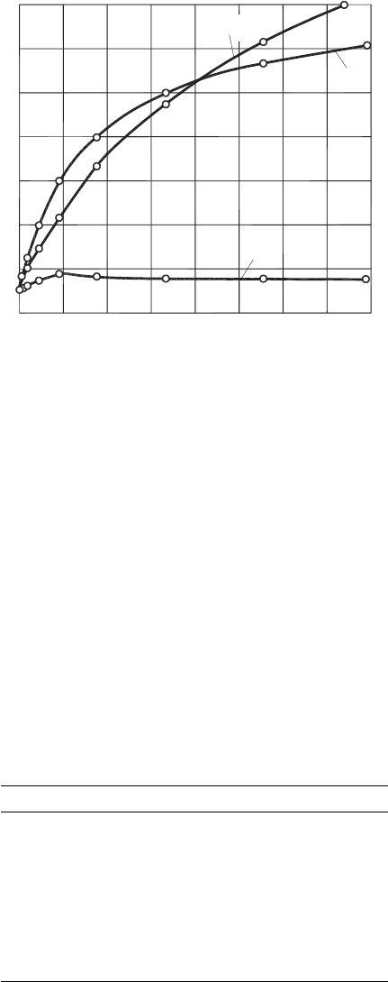
Fig. 3.48. Dependence of the cutting temperature θ, temperature at point O (θ
O
) and their ratio
on the Piéclet criterion (Pe).
The dependences of θ
O
, θ and their ratio θ/θ
O
on the Péclet criterion, Pe in turning steel
AISI 1045 using P20 (15% TiC, 6% Co, 79% WC) are shown in Fig. 3.48 for the following
conditions: τ
c
= 485 × 10
6
Pa,
C
p
ρ
w
= 5.02 × 10
6
J/
m
3◦
C
, w
w
= 8 × 10
−6
m
2
/s,
k
w
= 40.2J/
(
m ·s ·
◦
C
)
, k
t
= 27.2J/
(
m ·s ·
◦
C
)
, γ = 10
◦
, α = 10
◦
, κ
r
= 45
◦
, κ
r1
=
15
◦
, ρ
ce
= 0.01 × 10
−3
m, r
n
= 1 × 10
−3
m, f = 0.2 × 10
−3
m, d
w
= 2 × 10
−3
m,
t
1
= 0.141 ×10
−3
m, l
ce−a
= 2.88 ×10
−3
m, F
θ
= 1.75, E
ρ
= 0.71, D = 0.05. Values
of Pe and Br used in calculations are shown in Table 3.4.
The results of the calculations and analysis of Fig. 3.48 show that although the cutting
speed is very high, the maximum temperature at point O in machining steel AISI 1045 is
relatively low falling in the range between 82 and 185
◦
C. When Pe = 20, this temperature
has its maximum θ
O
= 185
◦
C and then it reduces assuming practically a constant value
Table 3.4. Pe and Br as functions of the cutting speed.
ν
(
m/s
)
Pe Br
0.062 1.1 0.452
0.123 2.2 0.573
0.237 4.2 0.562
0.493 8.6 0.562
0.950 16.7 0.502
1.9 33.5 0.532
3.93 70.0 0.573
6.17 109.0 0.641
8.85 156.0 0.641
Tribology of the Tool–Chip and Tool–Workpiece Interfaces 199
of θ
O
= 151
◦
C. The cutting temperature increases with the cutting speed, ν(Pe) from
130 to 1240
◦
C and thus the ratio θ/θ
A
increases from 1.6 to 8.2.
The foregoing analysis suggests that the similarity method is simple and straightforward
compared to the other methods of temperature determination. In the author’s opinion,
this method should be used instead of bulky analytical and inaccurate numerical methods
in the simulation software packages.
Experimental methods. The great difficulties in predicting temperatures at the interfaces
even for very simple conditions led to the development of a number of experimen-
tal techniques to measure temperatures in metal cutting. These can be broadly divided
into two categories as non-contact and contact methods. Among non-contact methods,
microstructural (metallurgical) method and infrared thermography are predominant
nowadays. Among the contact methods, temperature measurement using thermocouples
is the most common.
Microstructural methods. These are based on the correlation between temperature
and the microhardness and metallurgical structure of the workpiece or the tool materials
and the temperature. Normally [104–106], the correlation between microhardness and
maximum temperature that occur during cutting is used to determine the temperature
distribution in tools made of high speed steel. There are two drawbacks of this method:
• The accuracy is low reaching at best ±25% [105].
• It can be applied only for certain types of tool materials such as high speed steels. It is
not applicable for carbide, PCD and ceramic-based tool materials used nowadays.
Other examples of metallurgical methods are the use of powders [107] or physical vapor
deposition (PVD) coatings [108] applied on a section of split tool or split workpiece,
and chemical element substitution in the tool [109,110]. Knowing the melting point
of the introduced alloys, it is possible to reconstruct the temperature field by drawing
isothermals on the scaled drawing of the tool or workpiece section after cutting and by
metallographic analysis. This method, however, suffers severe drawbacks as:
• Any material melts when its temperature reaches the melting point and is allowed
to stay at this temperature for sometime. Basically, there are two types of transfor-
mation diagram that determine this time, namely, time–temperature transformation
(TTT) and continuous cooling transformation (CCT) diagrams. Time–temperature
transformation diagrams measure the rate of transformation at a constant temper-
ature. In other words, a sample is austenitized and then cooled rapidly to a lower
temperature and held at that temperature whilst the rate of transformation is mea-
sured, for example, by dilatometry. Continuous cooling transformation diagrams
measure the extent of transformation as a function of time for a continuously
decreasing temperature. In other words, a sample is austenitized and then cooled
at a predetermined rate and the degree of transformation is measured, for example,
by dilatometry. A simple analysis of these diagrams for common work materi-
als shows that there is not sufficient heating time available in metal cutting and
the rate of cooling is not known. As shown by Astakhov (p. 138 in [36]), at a
200 Tribology of Metal Cutting
typical cutting regime, a microvolume of the work material is exposed to high
temperatures during the time period of 0.000014–0.00075 s that might not be suf-
ficient for melting even if the temperature of this microvolume reaches the melting
point.
• When using various coatings on the tool and workpiece, a concern is that
these coatings change the thermal properties of the tool and work material. For
example, Outeiro, Dias and Lebrun reported [111] that a coating applied on
the tool dramatically changes the temperature distribution in the metal cutting
system.
• Because this test is of a post-process nature, it is not possible to correlate the obtained
result with the time frame of the cutting process.
Infrared thermography. Infrared, infrared thermography, thermal imaging, infrared
radiometry, infrared imaging, and IR condition monitoring are all terms used in this grow-
ing field of temperature measurements. No matter which particular term is used, infrared
radiometrics and thermal imaging have a wide diversity of applications. The technique
allows for the monitoring of temperatures and thermal patterns while the equipment is
online and running under full load. It is increasingly used as an emerging experimental
technique in metal cutting for various temperature measurements. The major advantage
of infrared thermography is that it does not interfere with the cutting process. Photogra-
phy cameras with infrared-sensitive films [112–114], optical pyrometers [115–119] and
the infrared cameras [120–125] are typical apparatus that are used to detect the infrared
radiation from a zone of high temperature.
Infrared cameras are the most suitable for the determination of the temperature distri-
bution in the deformation zone [111]. Different infrared cameras have applications in
metal cutting studies, from the classical infrared scanning cameras with only one sensor
[120] to the most advanced infrared cameras having a detector with an array of sensors,
as is the case of the FPA (Focal Plane Array) infrared detector [121,122]. The latter
design allows for more accurate measurements when strong temperature gradients occur
as those in metal cutting systems.
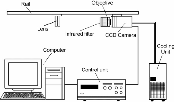
Figure 3.49 shows a schematic of a typical measuring setup used in infrared thermography
[111]. It includes a charge-coupled device (CCD) camera, objective, high-pass filter, a
pair of lenses of the convergent type and a graduated rail, where these listed components
were mounted. This assembly is then installed on a machine tool. In addition, cooling
and control units and a computer with dedicated data acquisition hardware and software
are connected to the CCD camera. The CCD camera is normally a gray-level digital
camera equipped with a special CCD detector, which presents high sensitivity, low noise
and high resolution. This camera is capable to work both in the visible and in the near
infrared regions (up to 1000 nm). The operating parameters of the CCD camera, such as
the exposition time of the CCD and the CCD temperature are set and controlled by the
control unit.
To analyze only the infrared radiation emitted by one object, the visible radiation should
be illuminated using for example a high-pass filter (or infrared filter). Outeiro, Dias
and Lebrun recommended [111] a filter that eliminates the radiation below 850 nm.
Tribology of the Tool–Chip and Tool–Workpiece Interfaces 201
Fig. 3.49. Schematic representation of the thermal imaging setup (Courtesy of J.C. Outeiro).
Such a filter is mounted directly into the objective of the camera. Therefore, the CCD
only receives radiation in a wavelength range between 850 and 1000 nm.
To analyze precisely the temperatures in the deformation zone, the size of the temper-
ature field analyzed by the camera should be of the order of a few millimetres, and
this area should be sufficient to cover the zone around the tool tip. The desired area
(spatial resolution) for temperature measurements is achieved, using, for example, a
pair of magnifying lenses placed between the camera and the machining zone. Because
the precise adjustment of the focal distance of the two lenses is needed, the camera
is mounted on the same graduated rail as the lenses. To obtain a fixed spatial reso-
lution during temperature measurements, the camera must follow the motion of the
objects under analysis, so, it should follow the feed motion of the tool. Therefore,
the assembly that includes the CCD camera, objective, infrared filter, pair of conver-
gent lenses and a graduated rail must be installed on the carriage that has the feed
motion.
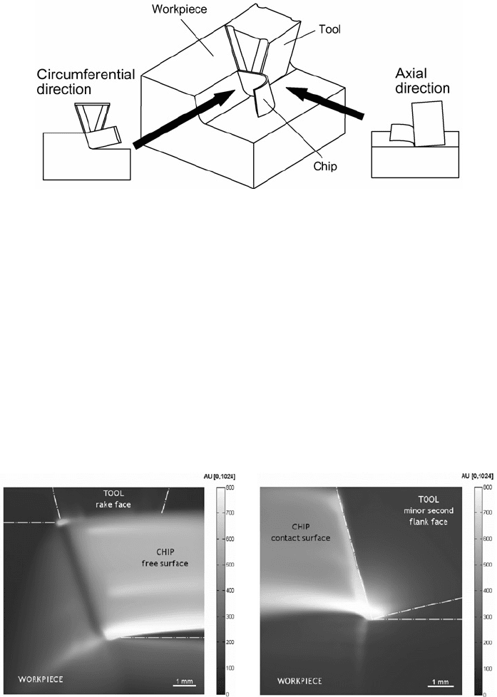
To analyze the temperatures in the zone around the tool tip at different angles with
respect to the tool reference plane, a special structural support is to be used. Such a
support allows changing the orientation of the rail, and thus the camera. Normally,
temperatures are analyzed in the zone around the tool tip in the direction parallel to the
axis of rotation of the workpiece (the axial direction) to the direction normal to this axis
(the circumferential direction), covering a range of angles between 0 and 90
◦
. These
directions are shown in Fig. 3.50.
The sequences of gray-scale images acquired by the camera are stored in the computer.
In the post-process stage, these images are converted into temperature-scale images
(temperature distribution) using appropriate calibration curves.
202 Tribology of Metal Cutting
Fig. 3.50. Schematic representation of the directions of temperature measurements using the
thermal imaging equipment (Courtesy of J.C. Outeiro).
Examples of measurements are shown in Figs. 3.51 and 3.52 for the cutting tool with
the following cutting geometry: normal rake angle γ
n
=−4.29
◦
, the normal flank angle,
α
n
= 4.29
◦
, normal wedge angle, β
n
= 90
◦
; inclination angle of the cutting edge,
λ
s
=−14
◦
, tool cutting edge angle, κ
r
= 72
◦
, nose radius, r
n
= 0.8 mm and tool
cutting edge radius ρ
ce
= 0.044 mm.
Although it has a number of obvious advantages, infrared thermography suffers some
limitations:
• The most severe and relevant to metal cutting studies is that it can only be applied to
determine the temperature of surface if this surface is available for direct observation
(
a
)(
b
)
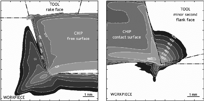
Fig. 3.51. An example of temperature measurement: infrared images obtained with the camera
placed in the (a) circumferential and (b) axial directions, showing the tool, chip and workpiece
(Courtesy of J.C. Outeiro).
Tribology of the Tool–Chip and Tool–Workpiece Interfaces 203
(
a
)(
b
)
Fig. 3.52. Temperature distribution on the chip and on the uncoated tool, obtained with the camera
placed in the (a) circumferential and (b) axial directions. Cutting conditions: work material steel
AISI 1045, uncoated tool, cutting speed ν = 125 m/min, feed f = 0.05 mm/rev and depth of cut
d
w
= 5 mm.
by the infrared camera. As seen in Fig. 3.50, the temperature of the chip’s free surface
and one side of the tool chip contact can only be measured. As such, the maximum
contact temperature and its exact location with respect to the cutting edge may not
be determined properly. As seen in Figs. 3.51 and 3.52, the maximum temperature
is measured at the region closely adjacent to the cutting edge while it is well known
that the maximum temperature under similar cutting conditions occurs at a certain
distance from this edge [36,37,57].
• Another factor that can lead to erroneous temperature readings is the geometry of
the surface being scanned. A concave surface tends to concentrate more energy
into the scanned area, just as a magnifying shaving mirror focuses sunlight, and
presents a higher emissivity. Similarly, a convex surface disperses the energy with
an opposite effect, showing a lower emissivity. Flat surfaces, especially polished
ones, do not emit radiation equally in all directions so the angle at which a flat
surface is viewed will have an effect. The more the angle deviates from 90
◦
to the
surface, the lower the apparent emissivity becomes, and the greater is the possible
temperature error if this is not taken into consideration. And for highly reflective
objects, the polarization effect has to be taken into account.
• An accurate knowledge of surface emissivity is essential for applications in infrared
measurements. Direct measurements of surface emissivity are difficult. The true
material emissivity value is a continuous changing property (dynamic) based upon
many material and application factors during the heat cycle. As with tempera-
ture, emissivity depends significantly upon the wavelength. In order to make an
204 Tribology of Metal Cutting
accurate measurement, all the instrument parameters must be known (wavelength
and bandwidth). Very few materials and applications have a fixed emissivity.
• The application of this technique is limited to dry cutting conditions.
• When classical infrared scanning cameras are used, it is difficult to evaluate with
sufficient accuracy the high temperature gradients and high dynamic phenomena,
which is the case in the metal cutting process.
• High cost of infrared cameras.
Over the recent years, low-cost camera solutions were being applied to the determination
of the temperature distribution on the tool and chip in orthogonal cutting [115,126,127].
These CCD cameras operate in the near infrared spectrum (wavelength between 400 and
1100 nm) and, therefore, they are classified as Very Short Wave (VSW) cameras [128],
compared to the infrared cameras referred above, which are classified as Short Waves
(SW) and Long Waves (LW) cameras, respectively [128].
Thermocouples. Researchers in the field of metal cutting have been using thermocou-
ples since the 1920s [34]. There are three basic types of thermocouples used in metal
cutting: embedded, running and tool–work. The running and tool-work thermocouple
techniques are specific to metal cutting studies [34,36,57] while embedded thermo-
couples utilized well-developed methodology used in temperature measurements in
various applications [129–131].
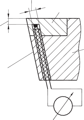
The principle of temperature measurement with an embedded thermocouple is shown
in Fig. 3.53. The thermocouple is placed in a small hole made in the cutting tool. The
diameter of this hole should be as small as possible to reduce disturbances which may
have an appreciable effect on the distribution of the thermal energy in the cutting tool
and thus the measured temperatures. Experience shows [36] that temperatures can be
measured with sufficient accuracy when the terminal thermocouple junction is pressed
against the cutting insert (the bottom of the hole) with a force of no less than 50 N.
As this is not always possible, it is recommended that the terminal end is welded to the
insert using condenser welding when HSS inserts are used. By placing thermocouple
holes in different positions of the insert, the temperature field and/or distribution can be
determined. A useful method to obtain such a field using a single thermocouple is as
follows: a thermocouple is initially placed in the most remote (from the cutting edge)
point of insert and then by regrinding the flank and the rake surfaces in any desired
sequence, the relative location of the thermocouple is moved to the desirable point
relative the cutting edge.
A standard thermocouple and standard calibration procedure can be used with the embed-
ded thermocouple technique in accordance with the ASTM Manual on the Use of
Thermocouples in Temperature Measurement (ASTM manual Pcn: 28-012093-40 by
committee E20 on temperature measurements, 1993), with other international standards
(for example, Thermocouples (IEC-60584), Industrial Platinum Resistance Thermometer
Sensors (IEC 751), Temperature Measurement Thermocouples (ANSI-MC96.1)). The
output of an embedded thermocouple is in the millivolt range and may be measured by
Tribology of the Tool–Chip and Tool–Workpiece Interfaces 205
Potentiometer
Cutting tool
Carbide insert
Approx. 0.3–0.5 dia.
Approx. 0.3–0.4 mm
Rigrindable flank
Fig. 3.53. Embedded thermocouple.
a digital millivoltmeter. The voltmeter is basically a current-sensitive device; hence, the
meter reading will be dependent on both the electromotive force (e.m.f.) generated by
the thermocouple and the total circuit resistance, including the resistance of connecting
wires. Therefore, the whole system, including the thermocouple, connecting wires and
millivoltmeter should be calibrated directly to furnish a reasonably accurate temperature
measurement.
A large number of commercially available electronic voltmeters (for example by Omega
Engineering Inc) and data acquisition systems (for example by National Instruments Co)
are suitable for thermocouple measurements. Among them, those providing a digital
output which can be used for computer processing of the temperature data are most
suitable, particularly when the cutting temperature is measured simultaneously with the
cutting force and/or other outputs of the cutting system.
The technique of temperature measurements in metal cutting with embedded thermo-
couples suffers some limitations:
• It cannot be used to measure temperatures at the tool–chip and tool workpiece
interfaces directly as the thermocouple is located at a certain distance from the
surface. As known from Ref. [37], a very great temperature gradient (along a normal
to the tool contact area toward in-depth of the tool material) exists at the interfaces
so the temperature reading provided by an embedded thermocouple may not reflect
the maximum temperature and its exact location. This drawback becomes more
severe when modern low thermal conductivity tool materials are used.
206 Tribology of Metal Cutting
• The exact contact condition at the bottom of the hole (Fig. 3.53) affecting tem-
perature measurements is not known.
• This technique cannot be used to measure the cutting temperature as the average
integral temperature.
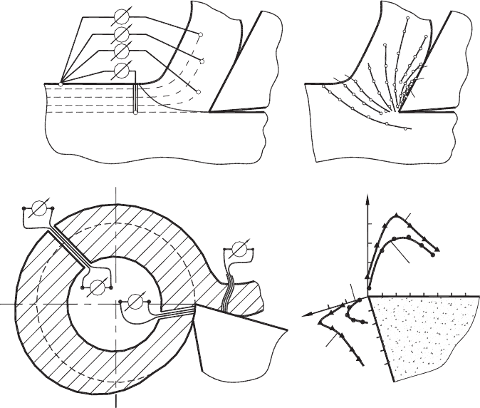
Running thermocouples are used when one wants to measure temperatures in the defor-
mation zone, i.e. at the partially formed chip and at the interfaces. The array of running
thermocouples to measure temperature distribution in the deformation zone and partially
formed chip is shown in Fig. 3.54(a). Insulated constantan wires of 0.12 mm diameter are
embedded in holes of different depths in the layer to be removed by the tool. When this
layer approaches the deformation zone, it deforms first elastically and then plastically
so that the wires are gripped securely in the holes, forming thermocouples in this way.
The cold junction of the thermocouples is secured to the workpiece far enough from the
Chip
Tool
20°C
68
125
170
220
340
460
580
625
490
A
1
B
1
C
1
D
o
C
o
D
1
B
o
A
o
Workpiece
Steel AISI 1045
(mm)
Titanium
alloy
Titanium alloy
Steel AISI 1045
q(°C)
q(°C)
600
1000
800
1.0
0.8
0.6
0.4
0.2
400
1.41.21.00.80.60.40.2
600
(mm)
(a) (b)
(c) (d)
Fig. 3.54. Temperature measurements with running thermocouples: (a) schematic representation
for measuring temperatures in the deformation zone and partially formed chip, (b) an example of
reconstructed temperature field in the deformation zone and the partially formed chip, (c) schematic
representation for the assessment temperature distributions over the tool–chip and tool–workpiece
interfaces and (d) an example of the results obtained.