Astakhov V. Tribology of Metal Cutting
Подождите немного. Документ загружается.


Cutting Tool Wear, Tool Life and Cutting Tool Physical Resource 227
As it follows from Eq. (4.3), the dimension wear rate is inversely proportional to tool
life but it does not depend on the selected wear criterion (a particular width of the flank
wear land, for example).
• The surface wear rate is the radial wear per 1000 sm
2
of the machined area (S)
h
s
=
dh
r
dS
=
(
h
r
−h
r−i
)
100
(
l − l
i
)
f
µm/10
3
sm
2
, (4.4)
where h
r−i
and l
i
are the initial radial wear and initial length of the tool path,
respectively and l is the total length of the tool path.
As it follows from Eq (4.4), the surface wear rate is reverse proportional to the overall
machined area and, in contrast to it, does not depend on the selected wear criterion.
• The specific dimension tool life is the area of the workpiece machined by the tool
per 1 µm of its radial wear
T
UD
=
dS
dh
r
=
1
h
s
=
(
l − l
i
)
f
(
h
r
−h
r−i
)
100
10
3
sm
2
/µm
. (4.5)
The surface wear rate and the specific dimension tool life are versatile tool wear charac-
teristics because they allow to compare different tool materials for different combinations
of the cutting speeds and feeds using different criteria selected for assessment of tool
life. Table 4.2 presents a comparison of different assessments of tool wear and thus the
tool life.
It is possible to use the width of the wear land at the tool point (nose) (current VB
C
and
initial VB
C−i
) instead of the radial wear (Fig. 4.1) to calculate the surface wear rate, i.e.
h
s
=
(
VB
C
−VB
C−i
)
100
(
l − l
i
)
f
µm/10
3
sm
2
. (4.6)
Although such a substitution is correct, it is difficult to correlate VB
C
with the dimensional
accuracy of machining. This is due to the plastic lowering of the cutting edge, which
often occurs in machining difficult-to-machine materials.
4.4 Optimal Cutting Temperature – The First Metal Cutting Law
4.4.1 The essence of the first metal cutting law (the Makarow’s law)
As discussed in Chapter 3, the cutting temperature is understood as the mean integral
temperature at the tool–chip and tool–workpiece interfaces as measured by a tool-work
thermocouple. As conclusively proven by Makarow [14], this temperature is the most
suitable parameter to correlate the tribological conditions at the discussed interfaces with
tool wear. Therefore, the correlation of this temperature with parameters of the cutting
system should be established.

228 Tribology of Metal Cutting
Table 4.2. Comparison of different characterizations of tool life.
Characteristic Designation/equation Restriction factors
Possibility to use in calcula-
tions of dimension accuracy
Cutting speed (ν (m/min))
Cutting feed (f (mm/rev))
Dimensions of the
machined part (surface)
Tool wear VB
m
or VB
r
Machining time without
adjustment or
replacement of the tool
(min)
T
c−l
++− +No
Number of part produced
without adjustment or
replacement of the tool
N
p−l
−−+ +No
Length of the tool path L
c−l
= νT
c−l
−+− +No
Area of the machined
surface
A
c−l
= 10νT
c−l
f −−− +No
Volumetric or mass tool
wear
m
w
−−− −No
Linear relative wear h
l−r
=
(
h
r
−h
r−i
)
1000
(
l−l
i
)
−+− −Yes
Dimension wear rate ν
h
=
νh
l−r
1000
++− −Yes
Surface wear rate h
s
=
(
h
r
−h
r−i
)
100
(
l−l
i
)
f
−−− −Yes
Specific dimensional tool
life
T
UD
=
(
l−l
i
)
f
(
h
r
−h
r−i
)
100
−−− −Yes
Note that “+” means that the restrictive factors should be kept the same when using this characteristic for
the comparison of cutting tools and regimes.
To do that, a simple factorial design of experiment (DOE) (discussed in detail in
Chapter 5) can be employed. As the result of DOE, the following equation to corre-
late the cutting temperature, θ
ct
with parameters of the cutting regime for a given work
material is obtained
θ
ct
= C
θ
ν
n
ν
f
n
f
d
n
d
w
, (4.7)
where C
θ
is constant that depends on the properties of the work material, n
ν
, n
f
and n
d
are powers to be determined in DOE (Chapter 5).
Table 4.3 shows the constants and powers obtained in machining different steels. As
shown, the strongest influence on the cutting temperature has the cutting speed. Makarow
showed [14] that the tougher the work materials (in terms of its machinability) gets,
the stronger the influence of the cutting speed (compared to other machining param-
eters) becomes. Another important conclusion follows from the analysis of Eq. (4.7)

Cutting Tool Wear, Tool Life and Cutting Tool Physical Resource 229
Table 4.3. Coefficients and powers in Eq. (4.7). Tool material –
P20, rake angle γ = 8
◦
, flank angles of the major and minor
cutting edges, α = α
1
= 15
◦
, tool cutting edge angle κ
r
= 45
◦
,
tool cutting edge angle of the minor cutting edge κ
r1
= 15
◦
.
Work material C
θ
n
ν
n
f
n
d
AISI 1010 228 0.25 0.07 0.03
AISI 1020 269 0.27 0.15 0.10
AISI 1045 352 0.22 0.08 0.05
AISI 1080 224 0.33 0.11 0.07
AISI 07 326 0.28 0.12 0.07
and Table 4.3, namely that the same cutting temperature can be achieved using different
combinations of the terms of Eq. (4.7).
Analyzing a great body of experimental data, Makarow formulated the law [14] which
was presented as the First Metal Cutting Law (the Makarow’s law) by Astakhov [16,17]:
For given combination of the tool and work materials, there is the cutting temperature,
referred to as the optimal cutting temperature θ
opt
, at which the combination of minimum
tool wear rate, minimum stabilized cutting force, and highest quality of the machined
surface is achieved. This temperature is invariant to the way it has been achieved (whether
the workpiece was cooled, pre-heated etc.).
The first metal cutting law, established initially for longitudinal turning of various work
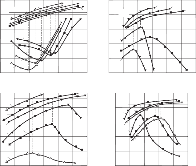
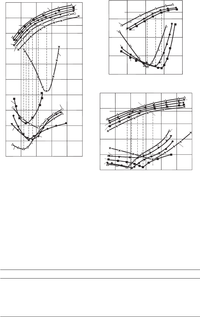
materials (example is shown in Fig. 4.5(a), was then experimentally proven for various
machining operations. Figure 4.5(b) shows its applicability in twist drilling, Fig. 4.5(c) –
in thread cutting, Fig. 4.5(d) – in gear hobbing. Considering Fig. 4.5(a), one can see
that when the cutting feed increases, the surface wear rate reduces. However, minimum
tool wear rates, when various cutting feed are used, occur at the same optimal cutting
temperature θ
opt
, although the amount of the surface wear rate varies more than 2 times.
Even more pronounced effect can be observed in Fig. 4.5(b), where the cutting feed has
a much stronger influence on tool life, represented by the total length of the tool path to
achieve VB
B
= 0.3 mm. As shown, there is a specific combination of the cutting speed
and feed at which tool life is at a maximum. Changing the cutting speed and/or feed on
either side reduces tool life while the minimum tool wear rate under a given combination
of these parameters corresponds to the optimal cutting temperature. Figure 4.5(c) shows
that tool life in thread cutting, represented by the total length of the tool path (L (m)) to
achieve VB
B
= 0.5 mm, has its maximum at the same optimal cutting temperature, θ
opt
under different combinations of cutting speed and feeds. Figure 4.5(d) shows that the
same conclusion can be drawn from the data for gear hobbing.
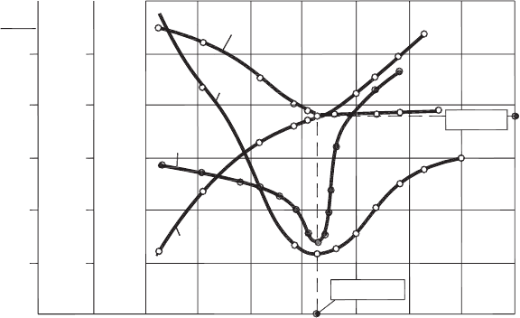
Figure 4.6 shows that the machining at optimal cutting temperature results not only
at the minimum tool wear rate but also leads to obtaining the minimum cutting force
and smallest roughness of the machined surface. As it follows from this picture, under
230 Tribology of Metal Cutting
400
3
16080 120
5
7
9
1
h
s
(µm/10
3
sm
2
)
1200
800
400
3
1
5
4
2
1
2
3
4
5
300
500
700
0
160
120
80
12816
40
0
4
L (mm)
1
2
3
1
2
3
L (m)
50
100
11070 90
q(°C) q(°C)
q(°C)
q
opt
q
opt
q
opt
q
opt
q(°C)
800
700
600
N (pc)
0
10
2
400
300
200
(a) (b)
30
40
150
200
250
10 20 30
14
18
6
(c) (d)
1
2
3
3
2
1
1
1
2
2
3
3
n (m/min) n (m/min)
n (m/min) n (m/min)
Fig. 4.5. Optimal cutting temperature: (a) turning, tool material – P30, work material – AISI 1045,
depth of cut d
w
= 1.5 mm using different cutting feeds: 1 – 1.4, 2 – 0.87, 3 – 0.61, 4 – 0.39 and
5 – 0.39 mm/rev, (b) drilling with twist drills, tool material – HSS T15, work material – AL 610
alloy, drill diameter – 15 mm, tool life criterion – VB
B
= 0.3 mm using different feeds: 1 – 0.28,
2 – 0.17 and 3 – 0.10 mm/rev, (c) thread cutting with a single-point cutting tool, tool material –
M10, work material – AISI 303, tool life criterion – VB
B
= 0.5 mm, using different feeds: 1 – 1.0,
2 – 1.5 and 3 – 2.0 mm/rev, (d) gear hobbing, tool material – HSS T15, work material – AISI
4140, module, m = 2 mm, number of teeth z = 61, VB
B
= 0.7 mm, using different axial feeds:
1 – 4.0, 2 – 2.5 and 3 – 1.7 mm/rev.
given cutting conditions, the optimal cutting temperature θ
opt
= 875
◦
C can be directly
correlated to the so-called optimal cutting speed ν
opt
= 1.28 m/s.
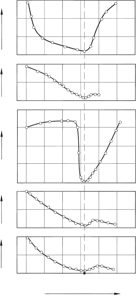
To understand the technical and physical background of the optimal cutting tempera-
ture, one should understand what happens with the work material at this temperature.
Figure 4.7 presents the answers to this question at the technical level. This figure shows
what happens with the most relevant (to machining) mechanical characteristics of the
work material when this material is brought to the temperature equal to the optimal
Cutting Tool Wear, Tool Life and Cutting Tool Physical Resource 231
0 n (m/s)0.4 0.8 1.2 1.6 2.0 2.4
200
500
700
900
1100
300
400
500
600
N
700
172
h
s
R
z
F
z
F
z
R
z
h
s
µm
µm
0.1m
2
25
5
7
9
11
23
21
19
θ(°C)
V
opt
= 1.28m/s
q
opt
= 875°C
q
Fig. 4.6. Experimental determination of the optimum cutting speed and temperature using longi-
tudinal turning of AISI 4340 steel. Tool material: carbide P20. Cutting regime: f = 0.15 mm/rev,
d
w
=1 mm.
cutting temperature. Particularly, the minima of the ultimate strength, σ
UTS
and elon-
gation, e
f
(which represents the strain at fracture) result in the minimum work done
in the fracture of the layer being removed as discussed in Chapter 2. The minimum
microhardness, HV assures the minimum of the normal stress at the tool–chip interface
as discussed in Chapter 3. The minimum Young’s modulus assures the minimum work
of elastic deformation (Chapter 2) while the minimum of h
r−s
results in minimum tool
flank wear.
To understand the discussed phenomena at the level of physical metallurgy, one should
recognize that metal cutting is the purposeful fracture of the work material as defined
by Astakhov [16]. As discussed in Chapter 2, the work spent in purposeful fracturing of
the layer being removed, i.e. its fracture toughness, should be considered as the prime
parameter in determining the cutting force and the energy spent in machining. Therefore,
one should consider the mechanics of fracture [18] and the importance of the process
temperature in this mechanics. Another important aspect of metal cutting, discussed in
Chapter 2, is plastic deformation that should be considered as a waste of energy. In metal
cutting, it is desired that the work materials have as small a strain at fracture as possible.
According to Atkins and Mai [18] and Komarovsky and Astakhov [19], there is a marked
increase in the strain at fracture and also in the work of fracture, at about 0.18–0.25 of
the melting point (T
m
); similar changes occur in other measurements of ductility such
as Charpy values (CVN), as shown in Fig. 4.8(a). It explains a number of “strange”
results obtained by Zorev in his tests at low cutting speeds [20]. This phenomenon also
explains the great size of the zone of plastic deformation observed at low cutting speeds,
and incorporated in the model discussed by Astakhov [16]. The known built-up edge
232 Tribology of Metal Cutting
600 800 1000 1200
150
250
350
s
uts
(MPa)
100
140
180
HV (MPa)
30
50
70
90
E (GPa)
100
140
180
h
rs
(µm/km)
20
40
60
80
10
θ
opt
Temperature (°C)
e
f
(%)
Fig. 4.7. Influence of temperature on the properties of pure iron.
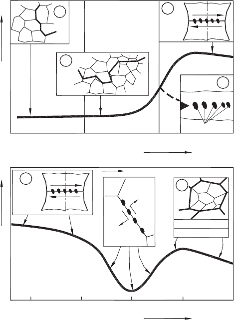
Cutting Tool Wear, Tool Life and Cutting Tool Physical Resource 233
voids particles
notch
D
C
B
A
0.1 0.2 0.30
(0°K)
Ductility
Temperature, T/Tm
Temperature, T/Tm
Ductility
Room Temp
0.4 0.5 0.60.3
Sliding
Cavities
DE
Recrystallisation
Partial
Full
(a)
(b)
Voids
C
Voids
DIFFUSION IMPORTANT
Fig. 4.8. Changes in ductility and typical associated mechanisms of fracture for bss materials:
(a) at temperatures <0.3 T
m
: (A) low-temperature intergranular cracks, (B) twinning or slip leading
to cleavage, (C) shear fracture at particles, (D) low energy shear at particles; (b) at temperatures
>0.3 T
m
: (C) shear at particles, (D) cavities along grain faces, (E) recrystallization suppresses
cavitation.
is the result of the discussed high plasticity region in front of the tool rake face within
the contact length. Exceptions are certain fcc metals and alloys (Al, Cu, Ni, Pb) that do
not normally cleave. As such, there is no transition in values, which gradually rises with
temperature.
The increase in ductility over the “transition temperature range” is followed by a gradual
drop beyond approximately 0.35 T
m
. It is believed that it happens due to the contin-
uous fall in the Peierls–Nabarro stress which opposes dislocation movement, coupled
with the emergence of cross-slip (as opposed to Frank–Read sources) as a dislocation
generator as the temperature is raised [18]. In the author’s opinion the cause is in
dilation–compression reactions as explained in Ref. [19].
234 Tribology of Metal Cutting
At high temperatures, grain boundaries become significant. Below approximately 0.45 T
m
grain boundaries act principally as barriers inhibiting cleavage and causing dislocation
pile-ups. At higher temperatures, the regions of intense deformation, which are contained
within the grains at lower temperatures, now shift to the grain boundaries themselves.
Voids are nucleated and then cracks develop on the grain boundaries. Shear stresses on
the boundaries cause relative sliding of the grains, and voids are reduced in the region
of stress concentrations (see Fig. 4.8(b) – position D). Therefore, the region around this
temperature can be termed as the ductility valley. Experiments showed [14] that the
reduction of plasticity may reach two fold and even more for high alloys. The presence
of this valley is the physical cause of the existence of the optimal cutting temperature.
At temperatures
(
0.5–0.6
)
T
m
, recovery and re-crystallization processes set in (recov-
ery relates to a re-distribution of dislocation sources so that dislocation movement
is easier, and in re-crystallization, the energy of dislocations generated during prior
deformation is used to nucleate and grow new grains, thus effecting annealed struc-
ture over a long time). The net effect is increased ductility causing a bump shown in
Fig. 4.8(b).
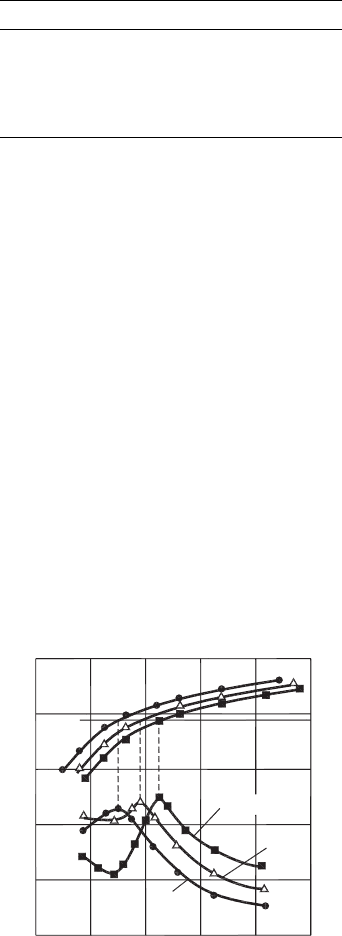
4.4.2 Major consequences of the first metal cutting law (Makarow’s law)
The following consequences of the first metal cutting law are of great importance in the
tribology of metal cutting.
Consequence 1: For cutting tools with various combinations of cutting geometry param-
eters (Appendix A) – rake, flank, inclination, tool cutting edge angles, nose and cutting
edge radii, etc. – the optimal cutting temperature corresponds to the points of minimum
on the curves representing the dependence of tool wear rate on the cutting speed while
the optimal cutting speed corresponding to each and every particular case varies in a
wide range. Figure 4.9(a) and Table 4.4 show an example of experimental verification
of this consequence.
Consequence 2: The minimum tool wear rate is achieved at the same optimal temperature
in dry cutting and in cutting with various cutting fluids (media) using various methods of
cutting fluid supply. Figure 4.9(b) demonstrates an example of the obtained experimental
data. As shown, the optimal temperature is the same for dry machining as well as for
machining using different cutting fluids.
Consequence 3: The optimal cutting temperature is the same for various combinations of
the temperature of the preheated workpiece and uncut chip thicknesses. This is illustrated
by an example shown in Fig. 4.9(c) and Table 4.5. In other words, the optimal cutting
temperature does not depend on or is invariant to a particular method by which it was
achieved.
Consequence 4: Variation of the workpiece diameter in turning and boring leads to a
significant change in the optimal cutting speed (i.e. the cutting speed corresponding to
the minimum tool wear rate). The reason for this is discussed in Chapter 2, where
the interactions of the deformation and thermal waves are considered. The optimal
Cutting Tool Wear, Tool Life and Cutting Tool Physical Resource 235
0 40 80 120
400
600
200
800
600
400
800
1
2
4
3
5
6
5
4
1
2
3
200
400
1000
10
n (m/min)
n (m/min)
n (m/min)
6040020
400
800
1200
20
30
302010
0
40
200
600
400
800
0
1
5
4
3
2
5
4
3
1
2
(a)
(b)
(c)
1
1
2
2
3
3
h
s
(µm/10
3
sm
2
)
h
s
(µm/10
3
sm
2
)
h
s
(µm/10
3
sm
2
)
q(°C)
q(°C)
q(°C)
q
opt
q
opt
q
opt
Fig. 4.9. Influence of cutting speed on the cutting temperature and tool wear rate: (a) wear in
turning AL 610 alloy, tool material – carbide P10 (14% TiC, 8% Co), combinations of the tool
geometry parameters are shown in Table 4.4, (b) wear in turning Haynes 263 alloy (29% Cr,
2.5% Ti), tool material – carbide M20 (92% WC, 8% Co), depth of cut d
w
= 0.5 mm, cutting
feed f = 0.08 mm/rev, curves: (1) dry cutting, (2) water-based (6%) cutting fluid, (3) oil-based
cutting fluid with chlorine and sulfur, (c) wear in turning Haynes 263 alloy with pre-heating of the
workpiece, tool material – carbide M10 (92% WC, 8% Co), depth of cut d
w
= 0.5 mm, feeds and
pre-heating temperatures are shown in Table 4.5.
Table 4.4. Regime and geometry parameters in Fig. 4.9(a).
Curve No. d
w
(
mm
)
f
(
mm/rev
)
α
(
◦
)
γ
(
◦
)
κ
r
(
◦
)
λ
p
(
◦
)
r
n
(
mm
)
1 0.5 10
10
45 −10 0.3
2
16
90 0.1
3 0.09
45
1.0
4 0.25 0
0.1
530
6 0.18 10 10 1.0
236 Tribology of Metal Cutting
Table 4.5. Parameters of curves in Fig. 4.9(c).
Curve No. f
(
mm/rev
)
θ
ph
(
◦
C
)
10.11 20
20.21 100
30.3 200
40.11 300
50.3 300
temperature, however, remains the same. This is illustrated by an example shown in
Fig. 4.10.
Consequence 5: If the structure and/or hardness of the work material are changed, the
optimal cutting speed is changed correspondingly, but the optimal temperature, remains
the same. This is illustrated by an example shown in Figs. 4.11(a) and (b) where the test
results for turning using the same high-carbon tool steel brought to different hardness are
shown. As shown, the optimal cutting speed changes with the hardness and metallurgical
structure of the work material (Fig. 4.11(a)) while the optimal cutting temperature remains
the same (Fig. 4.11(b)).
The summary of the considered consequences is as follows:
The optimal cutting temperature depends upon only the compositions of the tool and
work materials, so it can be determined once, and then used to optimize various cutting
processes where the same combination of tool/work materials is used. This temperature
does not depend on the type of cutting operation, tool geometry, parameters of machining
regime, particular type and method of application of the cutting fluid, etc.
200
100
0 204060n (m/min)
q(°C)
θ
opt
1000
800
600
300
L (m)
D
w
= 90mm
45mm
27mm
Fig. 4.10. Influence of cutting speed on the cutting temperature and the total length of the tool path
in machining workpiece of three different diameters in turning. Work material – Haynes 263 alloy
(29% Cr, 2.5% Ti), tool material – micrograin carbide M10 (94% WC, 6% Co), depth of cut
d
w
= 0.25 mm, cutting feed f = 0.09 mm/rev, tool life criterion – radial tool wear VB
r
= 30 µm.