Barzam A.B. Automation in Electrical Power Systems (Системная автоматика)
Подождите немного. Документ загружается.


CEAPTER ONE
.A'UTOMATIC
CONIROL
OF S}"I{CHRONOUS
GENERATON
EXCITATION
Sometimes
tbe voltage relay is corDected
to
a separate
voltage
tr8lslorEer
: I-3,
Excitation
Compoundiaq
with
Cuqulative
which
is
LqBd only
by
the etcitation iegul4ting device apd it has
po
fuses and
i
Connertinn
.'t tr'.lectropq-gn€tic
Vellag€
circuit
breakers iD
the
E*suring
circuit.s. The circuits oJ tbe exoitation lorcing
Corlector
devices
ean
be also contro]]ed
by
blocking blown
fuses
in a
way
similar to the
remote-control
protection
of
transmission
lines.
To
improve
the
efficienc-v oi
the
excitation
forcing
devices, the
voitage
relays
are connected
to a forward
sequence
voltage filter
(Fig.
1-6a).
Often
this
II
vl
llf
-l
Ir
I
rsl
43
.t!
Generator
compounding,
i.e.,
changing
the
current
floq,in
the fieid
coil
as dictated
b-r' the
current,
florn' in
the statoi
with
a
view
to
improving
tbe
g.or-
rator
external
characteristic
is
accomplished_
b-v rectifying
and
add"ing tJ
the
fieid
current
(Fig.
1-7)
a
current.
proportionai
to
the
statoi
curent.
u8
uC
h)
ac
I
_J
k)
Fig. t-6. Ercitation
forcing with
the
aid
of relay
sequence
iilter
ia)
excitation
forcing circuit:
(b)
internal
connections
onnliaa*inn af lrralrwar^-.cdrrpnnp vn)trtp
'tn
lilt.cr' /rt)
oP'"veu'v"
"*'- "-ifi;a-i'e-ffince
voiiiee'to
filter
is
of
the
resistance-capacilance
t-rrpe
(Fig.
also
potential diagrams of
the fiiter,
when
it is
connected through forward-
of
filter;
(c)
diagram
sholving
dirqrem shn*'inr annlieation nf
til
ter
1-6b). Shou'n in
the
Figure
are
at
the
forward
and backward-
sa tis-
(1-s)
of the
-->
Iph
conl
/. I
'
tDj
sequence
voltages.
It is clear
from the
diagram
that if the impedance of the
filter
arms
fies
tle
condition
R1: rs1: frcz:
R2:
+
,
+
tlre filter output
voltage at the
positirre
phase
sequence is 150
per
cent
rated
interphase
voltage.
The
excitation
forcing device
must
be furnished with switches
to
allor*'
attending
personnei
to remove
the
device
from
operation. Because of
the simple
conslruction
of
the
relay-type
excitation
forcing
system, its application is
liitel--v
to be usefui for all
senerators
and synchronous capacitors.
whaLever
the
automatic
excitation regulation devices
enployed
by these
machines.
I
tnmP
/ \
ta)
Fig. 1-7.
Compounding
device
principle
(o)
full current
compoundingl
(b)
pbaee
compounding
With
combined
use
of
a-compounding
device and
an eJectronagnetic
voltage
corrector, two
systems
fo-r
excitation
compounding
of geierators
miy
he
employed.-_These
are
't'ull
current
contpoundtng
and,-phast
io*pounding.
I;
the
case
of
ful]
current
compounding
the
actions
proportional
to the
stator
cur-
rent
and the generator
voltage-fed
from
the
iuitrument
current
aud
voitage
transformers
are
summed
up
.after
rectification
of
the
currents.
In the
caEe
of
phase
copPou-nding-this
is-done
before rectification
of
the
currents,
i.e.,
on
the
a.c.
side, which
allou's
the. effect
of the
phase
angle
between
the
stator
current
and the voltage
to
be taken
into
account.
n
In,
x
t,
B
.r','h\,>-
\
oo7
'i^,/
r\z-
V
,rrl
AT
L-i
s
I
rt
.cntnl,
[-:
,-T4
iu,
I
L-.
Qu
*i
't 't
't
I -
=
t_
+
!
t
-L
'.pn.
cpmp
CHAPTER
ONE
..
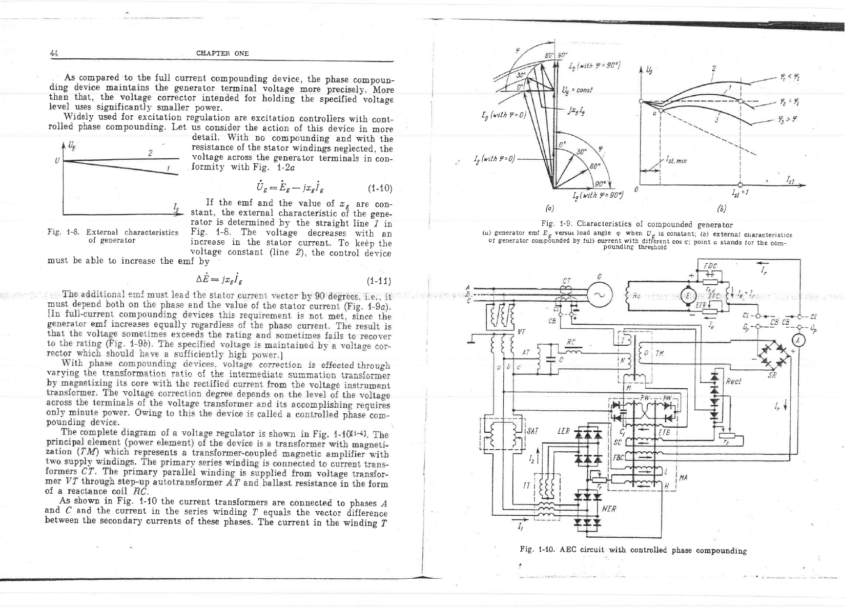
As_compared to
the
fuli
current
compounding
device,
the
phase
compoun-
d-ing
tievice
:laintains
the
generator
terminal
voltage
more preciseiy.'More
thal that, the voltage
corre-ctor
intended
for
holding
the
specified
-r,oltage
ievel uses
significanti,v
smalier
power.
\lTiiolrr rrcorll {^. or.aifo*i^- -^-"1^+.:^* ^-a ^--^rr^a:-- ---a--rr-- -
.,r
ruuvr.Y
spvq
rvr e^v^!curuu
reEul.clUIul!
alrt; V^(rl[.aLfU!
GOIlL.fOllgfS'WIln
COnt-
rolled
phase
compounding.
Let ul
consider the
action
of this
deviee
in
more
detail.
With no
compounding
and with
the
resistance
of
the
stator v-indings
negiected.
the
voltage
across
the generator
terminals
in
con-
formitl'
with
Fig.
7-2a
tt(*'ilh f
=0)
I,(nith 9=0)
Us:Es-jrcle
(1-10)
If the emf
and
the vaiue
of. z
r
are
con-
stant.
the external
characteristic
oI the
Eene-
rator
is
determined
by the
straight
line
I in
Fig.
{-8.
The voltage
decreaies
u,itb
an
increase
in the
stator
current.
To
keen
the
Fig.
1-9. Ciiaracteristics
oI
compounded
generator
(o)
geDerato!
emf Es
versus
Ioad angie
I
when
Uo
is
constant;
(b)
external
characterjstrcs
of
generator
coropbunded by
ful}
current.rvith..diflerent
cos
g;
point
a stands
for
tbe
eom-
pounding
thresboid
It(vith
f
=
90")
k)
f
-1
(b)
Fig.
1-8.
External
characteristics
of
generator
must be
able
ro
increase
tbe.JTf*:
constant
(line
2)'
the
contro]
db'ice
A,E:
jccl
e
(t-11)
+
I
varvins thp trensfnrirre ti nn i" +l^ ;i ;i." l;;;1;J;;*---
-.:,;;-;::";::-:;:::6^':
As
shown
in
Fig. 1-10
the
current
transformers
are
counected
to
phases
I
and
C
and
thg
e.r:rrent
in
the
sgries
s'indinc, ?
pmrqlq
{ha rva++n. iiffo*o--.-,
berween
rhe
seconaary
curr."tr
riiLr;;#E..
rll-#rrit
i,
iilT ##'dr,r?";
Fig.
{-1.0.
AEC
circuit
with
coutrolled phase
compounding
Lt
u
I
'I
I
I,9AT
I
I
'+,
tl
T'
,_j
Il
I
t
I
tFP **1 il r;
aa" L.
tt
-t
T-
\r.clArr,E;ft
uJ\-!.i
of traasformer
TM
musl have
such
a
phase
current
of the generator
and
the
the
current
in.the
?
windins
leads
the
The
above-mentioned.requirement
is
mr
to
tire
voltage
U",
deveioped
across
instrument
transformer
p'ith
delta-star
The
reactance
coil
(ftC)
makr.
tn.
.
dent
on
the
voltage
imposed.
The
react
AU?OI'ATIC
CON?AOL
OF
SYNCERO^.OUS
GENERA"OR
EXCITATION
+t
regulator
must
maintaiu.
z.
{
4
3_
ao,
un
Fig.
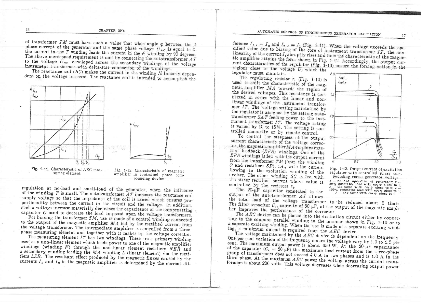
1-12.
Characterjstic
of
masnetic
amplifier
in
controlleci phase'-"om-
pounding
device
regulation
at
no-Ioad
and
smallload
of the
winding
I
is sm.all.
The
autotrar
supply
voltage
so that
the
impedance
portionaiity
between
the
current
in
t]:
such
a
voltage
increase
materiallv
decre
capacitor
C
u-sed
to
decrease
the
load
:
For
biasing
the transformer
fiy'.
use
to the.output
of
the
magnetic
ampiifier
the
voltage
transformer.
-The
intermediate
amplifier
is
controlled
from
a three-
pha:g
measuring
element
a1d
together
n'irh
it
makes
"p
iu*.
;;il;"
correcror.
The
noeasuring
element
/1
has two
windings.
Tirerfl.
"
prt*?r,
winding
used
as
a non-linear
eiement
which
feeds
plwefto
one of
irt.
*igr"iic
amplifier
winding,s (winding
tr)
th"ough
the
ooo-lio*rr
element
r."tit-i...
NER
and
a secondary-
winding
feeding
{he
tWn winding
^L
(linear
element)
r.ia thp renri_
fiers.LE.H.
The
1-rlltill
effecr
produced.lv
Cl,
*"lorti.
it";;;'"-;;;;.;;;
currents
.It
and
-I,
in the
magnetic
amplifi6r
is
dete]rminea
ly-
in*
currenl
dif-
O
and
rectifiers
Sn).
i.e..
*itn
ifr.
;;:;;:?
Fig..1_1,3.
Outputcunenrof
excjrarjon
flowing
in
the
excit,ation
winding
of
the
i"E"r"t",
*ilt'.;;;;;iird
phase
conr-
exciter'
The
other,
u'inding
^9C
is
}ed
with
p-oundirg
"*r".
[*.."to,
voliage
the
stator
rectified
".rrr"o..,T
;i^". t,^r.,^
controiled
bv tho
";"t";:
-
""""
YqruE
rs
50oz;
generator-toaii
witn'*=r-ip'ti,5!i't6
i
the
l-
?Gil#J#i.?dT[
a-"t"sy,r
li
i
Iorl's
ormer
to
be
reduceri
about
2
times.
F.
at
the
output
of
tlie
magnetic
an:pji_
correctol.
the
excitation
eircuit either
by
connec_
r
the
manner
shown
in
Fig.
f_10
or to
rse
is
made
of
_a
separate
eiciting
u,ind_
m
the
AEC
device.
device
is
dependent
on
the
frequencv.
rakes
the voliage-var_]r
b-v
1.0
to'f.5
pir
tut
650
W.
At-the
2O_[f
capacirance
num
feed
current
from
the
thiee_phase
thirdphase.A*he;+"ilfr
";;H;:;F",il"":l;:J#:ff
Sii,'.;l;$f,ii"n:
formers
is
abour
200
volts-'iutr
*it-g"
d;.;;;.;r"*tro
decreasing
ourput
po$Ier
Fig.
1-11.
Characterisrjc
of
AEC
mea-
suring
element
ir I
I'n.e i
I!
Set/
-
holatng
onc'
manu1l
resel
tircat !s
Ciosure
c!
conloctcr
$C
thPo
and
generolor
s*'ilcn
lurning o11
fDC
n^.^;nh nl rnnlnrlnr S( vhen
lhe
voltope
ii"ii'i'ti
ttiii,t
Circuil
of lhe
rclenoid
closing
SC
tlosure
o!
circuil..2
whcn
eircuil
.
bred*e'-
CB
it--[tt:t
"t
lrfun
lhe
roltage
loi!J-
lo circuits
f-4
ot
llA'l
and
l'lA-2
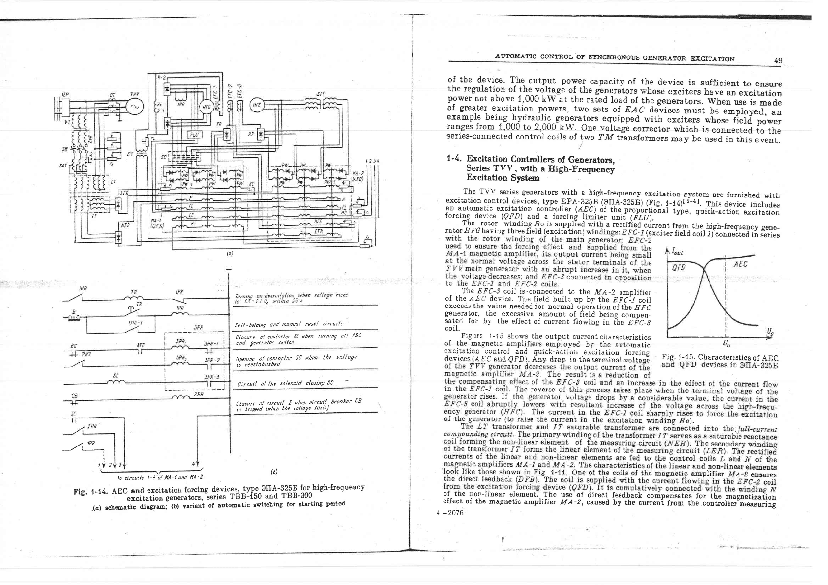
Err- t -t t A F(1 snrt cvcir'or.ion forcinp devices,
twe
S[IA-3258
for high-frequency
r
rE' r-
r='
""
""iii*tifr
o"
g"o"ttiors,
"series
T B
B-i
50
and
rB
B-300
_(a)
scbematic
diagram:
(b)
variant
of automatic
Ewitching
for starting
period
(6)
-.'a
AuToMATre
eoNTRor,
oF
s:nsc4oNoTts
GENE.EATOR
ExciTATiori
4g
of the
device.
The
output power
capacity
of the
device
is sufficient
to ensure
the
regulation
of
lLt^:qlt_qge
of the g-eneralors
whose
exciters
have
an
excitation
power
not
above
1,000
kW
at
the rafed
load
of the generators.
When
use
is
nade
of
greater
excitatior
powers,
two
sets
of.
EAC
d&'ices
must
be emploi"a,-""
exampl-e
being
h-vdraulic^generators
eguipped
n'ith
exciiers
whose
fi;id
t;*;;
ranges
from
1,000
to
2,000
kW.
One
"olage
corrector
which
is
ioonected
to
the
series-connected
control
coils
of two
TM
transformers
may
be usea
in this
e"eni.
1-4.
Exeitation
Controllers
of
Generators,
Series TV\/.
with
a
High-Fregueney
Exeitation
Systcm
The
TV\i series
generators
u'ith
a
high-frequency
excitation
systern
are
furnished
urith
excitation
control
devices,
type-EPA-B?tp
(?qA-8258)
(Fig.
1_ia)ti-al.
This
device
includes
an
automatic
excitation
controller
(aPC).
of
tbe
propbitio"nai
iyie, q"irf-".iion
excitarion
forcing
device
(QFD)
and
a
forcins
limiter
unii
tFtil_-'
forcing
device
(QFD.)
and
a
forcing
limiter
unii
titil.
The rotor
rrindins ,]?o is srrnnlied ntit.h a ro.rifio.l ^,',,
The rotor
uindins
fio
is
sunolied
Tvith
a rectified
cur"ent
frop the
high-freguency
gene-
rator
flFG
baving
three
fleld
(ercitation)
windinss:- n
pi-ir,iin;,
fi.Id liif
?i%i're4ed
in
series
The EFC-?
coil
is.connected
to
the
MA-2
amplifier
of the
AEC
device.
The fieid
buiit
up bl,
the
EFCjl
ioil
exceeds
tbe vaiue
needed
for
normal
dperation
of the
EFi
generator,
the
excessive
amount
of
field beins
comDen_
sated
for
by the
efiect
of
current
flowing
in ihe
niC-S
coil.
- .Figure
1-15
shos'-q the
output
current
characteristics
I
I
of the.magnet,ic
amplifiers
employed
by the
automaric
An
;;:.ii:'ii; o'f\'iftn;iii ,q:::\-:*il:.;-i:*r::, i:l:ilq
Fic.
i-15
characterisricsor ARC
oI
lne
non-llnear element.
T'he use of
direct
feedback
compensates
for
the
magnetizat"ion
effect
of the
magnetic
amplifier
MA-z, caused
by the
currenf
trom the-cooi"otll."o,."ifri;;
I
-2076
-r-
I
I
I
I
I
AUTOMATIC
CON?ROL
OF
SYNCERONOUS
GENERATOR
EXCITATION
51
utlAHltl-t{. t t\tt
in
tte
z'rc-s
Coil,
ii""t"n
iiJi,
mplifier
Nn:Z),
a
cunen"t
app_
and
in
the
EFC_]
coil.
After
a
opening
of the
linear
element
c
rator
is
Decessary
to
limit
the
vo
the
starting
conditions
to
0.5
of
th
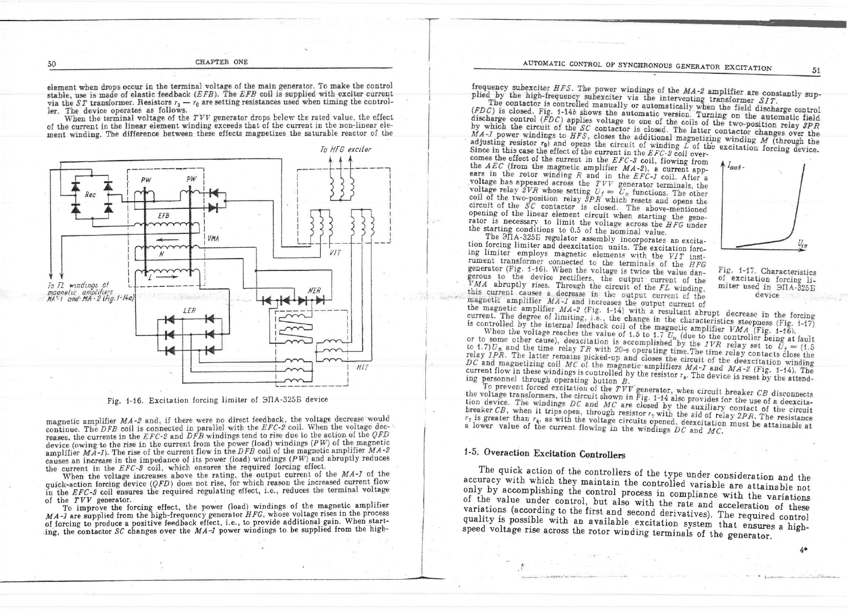
The
SrIA-3258
regurator
assembrl,
incorporates
an
excita-
tion
rorcing
limfter
and
deexcitation
rinits.
r[.
.r"it"iloi
ror"_
ing
limitei
employs
magnetic
element.
g,irh
fhp vrr tnat-
current
flou'in
tbese
windings
is
c<-rnrr"ii"E
t" il';"';;'"T;:",'"F;: .i!j^!',! -!
{f
ie'
1-14).
The
lo
flt'U
exctler
-----"1
l+
LIP
Fig.
1-16.
Excitation
forcing
limiter
of
SIIA-3258
device
of
the fVP
generator.
.'
'_ ';;""\;?
Ji..-i;y'q
.9{f":!r_l!:
t"l:l_q:-"_d),,y:"{*g:^9l,tl._"T.""s-:",T"-"111}j:::
MA-l
ale
supplle0
lrom
lne trrgl]-IrequerlcJ'B'elrc.raluI
If f trr
wIU.t_t_Yr-uo6',rr--'"
-'"
;i f;;.iil
t.'rffia""r
a
positivEfeeddack
efiEct,
i.e.,
to
provide
ad-ditional.gain.
When
start-
i;b,
;i';""*;d;;;;sc;fi;;d'
on*"-ih.
MA4
po*.i
wiirdings
to be
supplied
from
the high-
l-5.
Overaction
Excitation
Controllers
The
quick
action
of the
controllers
of
the
type
under
consideration
and
the
accuracy
with
which
they
maintain
the
controiied
variable
are
attainable
not
oniy
by
accomFlishing
the
control-pto"*-i"-r"-prir"*-ilh
ih*
ouri"tious
of
the
value
un{-er
c6ntrol,
but
alio
*iin
tit.
?t.
and
acceleration
of
these
variations (accordine
to
the first,
and S€ennd dori,,ori-,^.r
rnr-,-
:=---.
gualitv
is possible
i'irh
"o
"n"it"ntr
-.r"it"i;;;'r-;'r"r#.;ffr':ff;::
;"f,?fl1
speed volrage
rise
across
rhe
roror
windinl
i.r*ir.ri
or-tne-|eolii.o..
4*
CEAPTE.R ONE
AIITOMATIC
CONT&OL
OF
SYNCENONOUS
GENERATOR
EXCITATION
To
improve
the
stability
of
generators
operating
in
parallel
as
foilows
from
(1-3)
and
Fi.g.
1-2,
it
would be
.good
practice
to
accomplish
tle
control
process
by
ihe angla
6. However,
to take measurements
of
the
-ang-Ie
6 between
the eml
vector
of the
generator and
the
voltage
vector
of
the
busbars
of the receiving
s-ystem
}ocated
at
a
great
distance, often calls for
the use of
telemetering
means.
The
use
of remote
control
equipment
for the control
purposes
complisates
the
device
and
lowers.operation
reliability.
With
networks
of
simple
configuration
which use,
for
instance,
a
generator-
transforrner-transmission
line-receiving
system
set,
the angle
6 can
be determi-
ned
with the
aid of
the
so-called
phantom
diagrams
(see
Chapter
4)
which simu-
Iate the
impedance
from
the
point
of
the
geaerator emf
application
to the
P.oint
of
voltage measurement,
and
to the busbars
of
the
power roceiving
system-(this
impedance
opposes
the stator culrent,
tbe
corresponding
voltage drops
being
veCtor added
to
the stator
termiual
voltage).
However,
such
a measuring
technigue
has
not found
wide
application.
Moit
often
used
are overaction
excitation
controllers
which
perform the
contro]
fuuction
by
eiectrical
variables
dependent
upon the angle
6,
namely
by
the
value of ourrent
in
the transmission
line and
the voltage
at
the
line
point
ttnder measurement.
To
make
the control
process
more
rapid
and
stabie,
the
first
and
the second
derivatives
of
the
above-mentioned
guantities
are
intro-
duced
into
the
controi
equation,
or
the
value
of frequency
variation
and
the
,lerlvative of
this
variation, as
the
frequency
variation is
propor-tionai
to
the
first derivative
of
the
6
angle
variation,
whiie-the
ireguency
variation derilA-
tive
is
in
proportion
to its
second
deriva*uive.
The matLematical
expression
defining
the control
equation may
be
written
as
,d-n.'dnz
lJ
-
li6fi-r
lit
.--':-
i
ti.,t
--=-
'dt
'diL
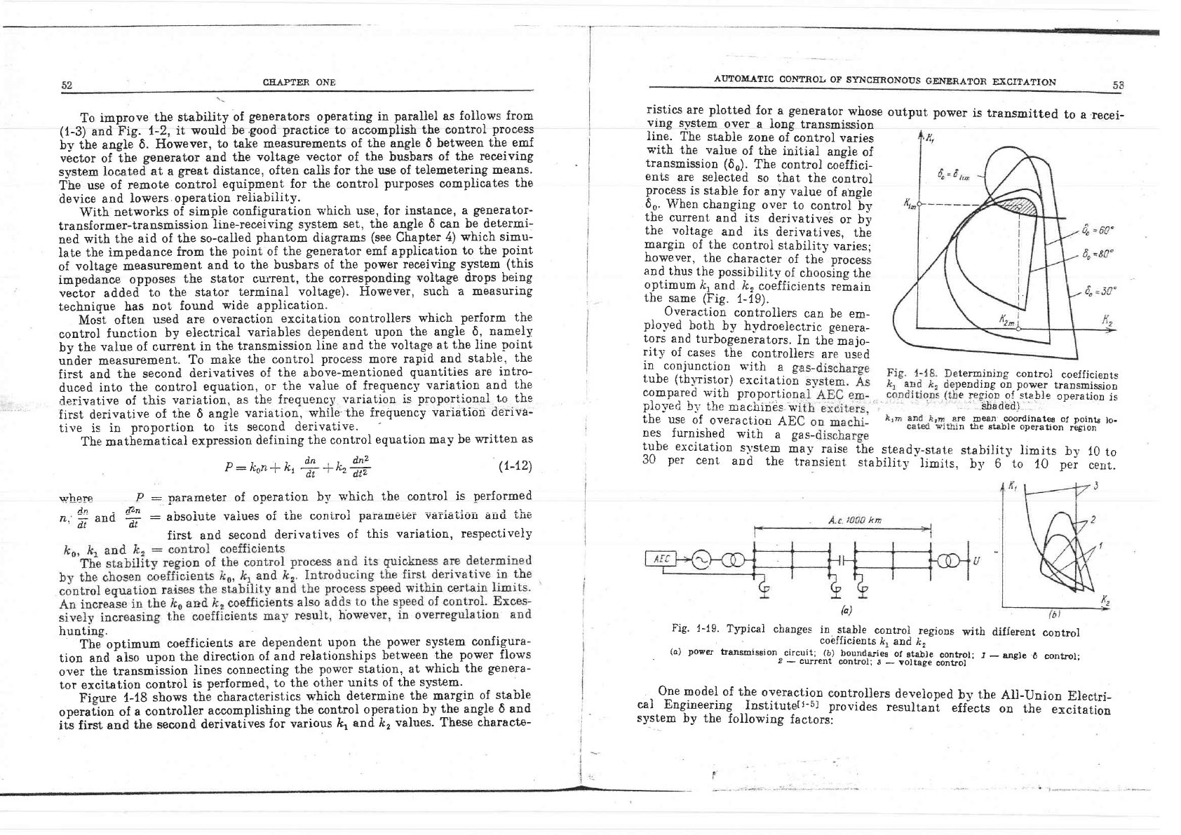
ristics
are
plotted
for
a
generator
whose
ving
svstem
over
a long
transmission
line.
The
stabie
zone
of control
varies
s'ith
-,he
value
of the
init,ial
angie
of
transmission
(60).
The
control
coeffici-
enis
are
seiected
so t,hat
the
controi
proces-c
is
stable
for
any
value
of
angle
6-0.
When
changing
over
to
control
by
tbe
current
and
its
derivatives
or bv
the
voltage
and its
derivatives,
th;
Fargin
of the
controi
stability
varies;
however,
the
character
of the
nrocess
and
thus
the
possibility
of
chooslng the
optimum li,
and k,
coef.f.icients
remain
the
same (Fig.
1-19).
Overaction
controllers
can be em-
plo-ved
-both
by
hydroelectric
genera-
tors
and
turbogenerators.
In
the
majo-
rity
of
cases
the
controllers
are
used
in
conjunction
rr"ith
a
gr
tube (tl-r'rirl"tl
excitation
termining
control
c'oefficients
compared
with
proporrion
fiiilf"lll:.",ni'#:i"1iH"t:
plc;red
bi.
the
n:acirines
wj
sbaded)
the
USe
Of
Overa.tiOn
AE(
re
Dean.
coordinatF
ot
points
lo-
nes
furnished
with
"-!rr-,
n tire
sta-ble operation
re5:ion
tube
excitation
s)'stern
ma1.' raise
the-steady-stat,e
stability iimits
by
10
to
30
per
cen'r,
and
the
trinsient
stability
iimits,
b],
6
"to
l0
per
cerrt.
output
power
is transmitted
to
a
recei-
rrrhere P
rln - [Zn
z.*and6.
hunting.
The-optimum
coeffioients
are
dependegt
upon
the_power
system configura-
tion and
also
upon
the
direction
of and
relationships
between
.the-
power
flows
over
the
transmission
]ines connecting
the
powcr station,
at
which the
genera-
tor excitation
control
is
performed, to
the other
units of
the
system.
Figure
{-tB
shows
the
characteristics
which
determine
the
margin
of stable
opr."iioo
of
a controller
accomplishjng
tbe controi
operatio_n
by
the angle 6 and
its
first and
the
secoDd
derivatives
for
various
k,
and ft,
values.
These
characte-
(1-12)
:
Dararnoter of operation
b-v
which the
control
is
performed
:
absoiuie
vaiues of
the coniroi
parau.ete-r
varia-uion
anri
'uhe
first and
second
derivatives
of
this
variati.on, respectively
(")
Fig'
1-19.
Typicai
changes
in
s_table
control
regions
with
different
control
.
cobfficients
/r,
and A,
-
-
(a)
power
tranrmissionrcircuit;-l?)
J""""l3tT'r"L"l"t'rxo#.gl*l?t'
'r
-
ansle
6
control;
One
model of
the
overaction
controllers
developed
by the
AII-Union
Electri-
cal
Engineering
,inst,ituteit-5i
proviries
resultanl
effects
on
the
excitation
system
by the
following
factors:
I
AuToIvrATrc
coNTRoL
oF
syNcERoNous
ctNERAToR
ExcrrATroli
55
il0v
4S0Hz
ttOV,450Hz
GCSII
-W
J{
CEIAPTER
ONE
(a)
By
the voltage departure
A
U
from the
rating,
v'ith
the
coefficient
a ?A
excit. unit
fi6U:
Cr-;5i15;if
the voltage
derivative
(by
the
voltage
variation
rate)
da
a
dI
dt
(b)
BV
the
value
of
with the
coefficient
(c)
By
the
variation
I
7, n
excit. unit
rig,:
g
trg ,
Tit.
uoitl,
oJ the
value
of
stator
current with
the
coefficient
kr:o
to,
excit'
unit
cur.
unit
(d)
BV
the
value
of
stator
current
derivative
(by
the
current variation
rate)
with the
coefficient
k't,:o
to
8.r
l-l!i',,],lll
cur. unrt/s
(e)
B-v the
vaiue
of
the second
stator
current,
derisative
(b1'
the
current
variation
rate acceleration)
ffi
w'Lth
the
coefficient
k'i,:0
to
1"rr;
"'!ii'il:=YI,t
-"--
cur.
unitlss
(f)
By
tlie
value
of the
rotor current derivative
(bv
the
current
variation
speed)
u'ith the
coefficient
ki,
,ot:
0
to
Z.
z
--era!-lntl-
rot..
cur. unjt.is
The
nominal
values
of current
and
voltage
are assumed as excitation
urril.-s.
The optimum
gain
factors
for various
channtls are
determined for
eacir
device
b5r
means
of
precalculation
and
actual tests in the
po\r,er
s_vstems.
In order
to
make
the
external links
of
the
regulator
more simple. the effect
produoed by tiie freguency
and its derivative
may be used instead
of that
pro-
duced by
the
derivative of
line
current. Experiments
on mathematical
models
have shown,
however,
that system
hunting ma]'
occur,
when power
close
in
vaiue to
the
steadv-state
stability limit
is transmitted. In addition,
anaJyses
of a series
of
emergency
situatious
have
shou'n that undesirable
falls
in the
busbar
voltage
of the station
occurred due to the
use of
frequenc-v
channel,
when
an
active
power
shortage
arose at that
portion
of the
power
s_vstem
u'here
[he station furnished v'ith
a
AER
was located.
Because of
this
the frequency
controi channel
is
mostly
used
for control
of synchronous capacitors.
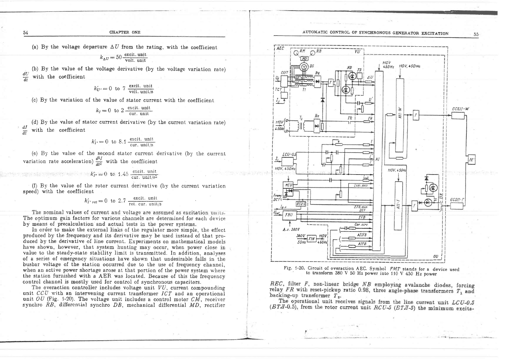
The overaction controller
includes voltage
unit
7U, current
compounding
unit
CCU
rtith
an
intervening
current
transformer
ICT and
an
operational
unit OU
(Fig.
1-20).
Tbe
voltage
unit
includes
a
control motor CAI,
receiver
synciuo RB,
different,ial
synchro
DB, mechanical differential
MD, rectifier
luoffi,l
i
"
l'.il I
--l
|
,;o*
f
r-
I
I
I
I
I
trtttn/
iDct\
iL
t
Tcr
lr
I
t,
I
I
I
I
l
IL
I
I
t"*t,
l
rnrr F1----.l-_
- -:-.l
ll I I
I
l'--rll
rrrJ
ll I I
|atttt
i
T
L-----J
, ,,
(or'circ
I I I | |
j
.t.r.ttov
i-{il{-i il
I i
,
,,
._f,Fl
ll
I Wrqrhl4,il-{=-+--.1 rr
i
soHzt_r4souzlll
>=-
Arr.fr
I I
rl
lr
lr
lL
vi
Ftg.
I-24,
Circuit
of overaction
AEC.
Symbol
F447
stands for
a
device used
to
translorm
380
V
50
Hz
power
into
110
V 450
Hz
power
I
I
I
I
I
I
I
I
I
I
I
I
I
:
I
I
I
I
I
I
I
I
CHAPTER
ONE
tion unit
AIEa
which is
fed
from a
d.c.
transformer
(DCT),
and
the feedback
unir FB-U*
which
is acted upon,
depending
on
the
value
of the exciter
voltage
U
rot.
The output
eircuits
of the
operational unit
are
connected
to the u'indings
oi t,he
summing
ryagnetic
amplifiel
,4.I
s'hich
serves
as the first
amplifier
s"uage.
The
second
amplifierstage is implemented
by the
magnetic
amplifiers
AII-W
^-l I f T fi mL^ -^*-^- *-:-l:-- ^--*^-r ^! rL^ t rf tr: - -- t.!. . .r
tJuu
Att-r. rus
Fowsl'
wr.u(rrug
gurrEJr.L
ur LIIe
AtI-
yl'
arrt.pluler
acIS
upon
tne
semiconductor
grid
control
svstem of the working
group
valves
GCSII-I|i,
while
the
current of
the power
winding
of the
AII-F amplifier
influences
the
AU?OMATIC
CONTROL
OF
SYNCERONOUS
GENERA"OR
EECI"ATIOIIi
semiconductor
grid
control
svstem
of
tbe
forc-
ing
group
valves
GCSII-F.
The action is eff-
ected
through
output filters
F
which
reduce
the
a.c. component
of the
outpur
voltage
to
150
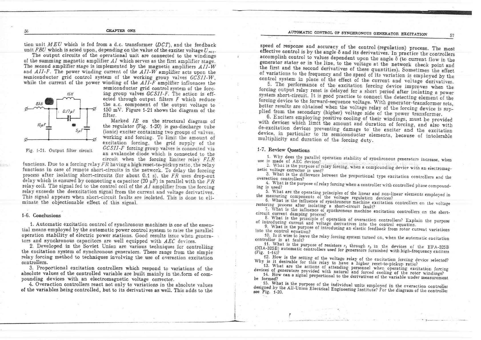
m\r. Figure 1-21
shows
the
diagram
o1
the
fil ter.
Marked
IE
on
tbe structural
diagram
of
the
reguiator
(Fie.
{-20)
is
sas-discharge tube
minate tbe
obiectionable effect
of this signal.
1-6.
Conclusions
3
Proportional
excitation
controllers which
respond
to
variations
of the
absolute
values
of the
controlled variable
are built
mainly in the,forn
of
com-
pounding
devic,es
with
an electromagnetic
voltage
corrector.
4. Overaction
controllers
react
noi;
only
to variations
in the
absoiute
values
of
the
variables
being
controlled,
but to its derivatives
as well.
This adds to
the
sp-eed.of
response
and
accurac-v_of
the
controi
(regulation)
process.
The
most
effective
control
i:
lv the
angle
6 and
its
derivativel.
l"
pti"[i..
the
controliers
accomplish
control
to
values
dependent
generator
staior
or
in
the
line, to
the
the
first
and the
second
derivative-q
oi
ing-of
their
windings,
must
be
provided
and
duration
of forcing,
and
also
with
age
to'
the
exciter
and the
excitation
uctor
elements,
because
of
intolerabie
rg
dut5.
1-7.
Review
Questions
1'
wh-v
does,
the
t::?ll:i
operation
stabilitl,
of
slnchronous
senerators
increase,
n,hen
use
is
made
of
AEC
der.ipes?
o.ti"2uJll,liil
t:r*:;#Ir"J'i"J'reiav
forcing,
,n'he,
I compouDding
tievice s'ith
an
erecnomag-
3' Hthat
is tbe
difference
between
tlre
proportional
tl,pe
excitation
controljers
and
the
overaction
controllers?
iog
f"
J:rtT
is the
purpo'se
of
relay
forcing
wben
a controller
r.'ith
controlled
phase
compound-
5'
what
are
the
operating
p.rinciples
of the
}inear
and
norr-linear
elements
emplol,ed
in
tbe
peasuring
compoi-ents
oi'tir",ioir";;
;rgui;;ilo'"devices?
6'
what
ls
tlLe
iottu"o""-oi
Jy-n"Lrooous
machine
excitation
controllers
orr rrrp vnrrqoo
iesi.oring,;-ro::"=.,fFl
i-s6isrjng
a
;h;;t*i.;It"
i""ftf^
;!',!g6c
machine
excitation
controllers
on
the
sbort_
overactjon
controllers?,
Erplain
the purpose
rs
into
the
control
equation.
tlastic
feedback
fiom
iotor
currerrt
variations
Lem
turned
on,
t,.ben the automalic
excitation
lt'
what
js
the.purpose.of
resistors
r,
tbrough
rs
in
the
devices
of the
EpA-szsB
[3111
?:ifi)
automatii
coltiolle.;
*;;
ror
[ererat6rs
rurnlshia
"'iiiii,i]hlirrsu.o"s,excirers
{2'
Hos'is
the
setting.of
tbe
voltage
relay
of
the
excitation
forcing
de.r,jce
se}ected?
lvbv
is
it
desirabte.
tor
ti,is-r;i;r";;
h:q;r-"
i,gi,.i'
rJset-to-pickup
ratio?
13'
!t?hat
are
tbe
actions
oi'attendinq
personnel
.".h;o'"o;t;;;iios".r";itrtion
forcrng
devices
of
generators
provided
o'it[-
ortu"a]l
irnd
forced
eooling
of
.t-h-e
rotor
u.indings?
14'
How
can
a
sigial
proportioo"f
io-tt"
;fi";;i;;
of
tbe
variable
under
m€asureme'r
be
formed?
"
r--r-'
15'
What
is the-purpoi;g
of
the
individual
units
employed
in
tbe
oreractjon
controller
designed
bv the
All-u;ioi
eteii.i."t
b;;i;;il;s
iir:tiiiliii
ro.
the
diagram
of rrre
con*oller
see
Fig.
1-20.
0./77F
58
CEAPTER ONE
U,
=
Arc
Uo=
U"a
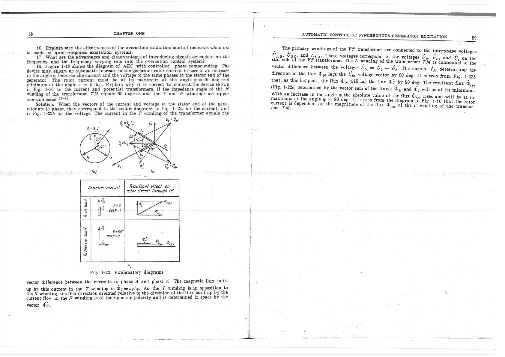
Fig.
1-22.
Explanatory
diagrams
vector difference
between
the
currents
in
phase
,{
and
phase
C.
The
magnetic
flux
built
up
bv this cupent
in
the
?
v,inding is
{ba
-hyl7.
As the
Z
winding--is in
opposition.to
the
tV
winding,
the flux
direction
oriented
relative
to the
direction
of
the
llux
burlt up
,by lPe
current
fio*' in
the
ff v'inding
is
of
the opposite
polarity
and is determined
in
space
by
tbe
oertor
Oi".
The
primary
windings
of the
PZ
transforrner
are
connected
to
tbe
interphase
voitages
!Oryr,!^r^r,,|?d,,gqn
These
volrages.co*e,qpond_ro
the
volrages
i^r-,-i;.;"d
ii.
on
the
star
side of the
7?
transformer.
The
n winding
of
the
iransioriler
?"lit
is"connected
to
the
vector
difference
between
the
voltag".
u6.
-
ab
-
u"
The
cunent
^r^*
determining
tbe
direction
of
the
flux
<iro
lags
the
u6. voltage
vector
by 60
deg.
Ii
is seen
f.rom
Fig.
t-Zzb
that,
as
this
happens,
the
flux
O*
will
iag
the
fiux
Oi
lV
g0
deg.
Tbe
resultart
ifu
A"".
(Fig'
t-22c)
determined
by the
vector
sum
of the
flures
<bn,
and
cD7
will
be
at
its
minimum.
with
an
increase
in-the
angle.,g,the
dbsolute
value
of
the
itux
rir"".-
rir..
".ra
*,ill
be
at
its
maximum
at
the
an^cl9_e-l-
90'deg.
It
is seen
fron
iir"tia.gram
in Fig.
i-10
that
the
rotor
current
is
dependent
on'the
magnitude
of the
flux
o;*-;'i"iil-i-*i'oTing'ir
the
transfor_
mer
TM.
AUTOMATIC
CONTRO!
OF
SYNCERONOUS
GENERA?OR
EXCIIATION,
59
F
{')
Startor circait
Resullan[
effeet
on
rolor
circui{
Iltrou"oh lll
\
s
s
q
\
q
e
R
\,
t
t
(c)
AUTOMATIC
VOLTAGE
REGULATIONChapter
Tuto
AUTOMATIC
VOLTAGE REGULATION
2-1.
General
h{aintaining
the
normal
voltage
in
a
power system
is one
of the
basic
ways
of
assuring
itJ
proper
performance. The
State
Standardt2-tl
specilies
that
the
maximum-permitted
voltage variation
at
the
load
terminals shouid
not
exceed
:t5
per
cent
of
the
rated
value.
Voltage
drop
beyond
t,he
specified
limits
mal
resuit
in
excessive
slippage
of
asyncbronous
motors with
resuitant
reactive
current
overload
of
the feeding
elements
and decreased
}uminous efficiency
of
:r=rlir"-"i
oo*ito*as
+-o
the
s5rstem
fle.ding
elsmsnt,s,
proper
loading and
unioad-
ing of individual
transmission
lines
and
appropriate selection
of
transformation
raiios
for step-up
and
step-down
transformers)
and also b1'
joint
operation
of
automatic
exlitation
controllers
of
asynclrronous
generators and
synchronous
eapacitors,
devices
which automatically
change,
when under
load,
the
trans-
foimation
ratios
of
power
transformers, remote
transformer
boosters
and
devices
*,!,iaI" o::*nnnofincllrr eu'itnh !1a-7or
flT e-nntinttorrslt;
rJeT\-r
t.hg canaCitivg
IOad
yvIlIU.ll
cLLIUlruouIwqlrJ
onrovu v
rer
vv!vrsqvqerJ
of
static balancers.
2-2. Use
of
AEC
Devices
Automatic, excitation
controllers
are used
to
maintain
the voltage
in
com-
pliance
with
the specified
characteristic
and
distribute
the
reactive
load
between
the
power
sources
under normal
operating
conditions
of
power
systems.
When
generators and
synchronous capacitors
are equipped
with AEC
apparatus,
a cbange
in
the
required
voltage
setting
is
accompijsLred by
special
automatic
devices,
i.e.,
voltage
controllers
or through
setting
devices
operated
by
attend-
ing
personnsl.
To
dccrease
the
voltage
ae.ross
the
terminals
of
a
generator
or
a synchronous
;:t1"j'i,::":':*i*"::f:T'ji:*::.:::'.l: :.':I 11
*'-'-"
th'
;."f9,s""pprieJ
geqr
eresEuuo
vl
r,trt
yuroage
gorrgcf,or.
In
tnr_s
casg
thg
output
current
of
the
corrector
oecreases.
To
increase
the
termiaal
voltage
of the generator
or synchronous
capacitor,
the.
voltage
imposed
on the
lineir
and
noilio""t
Li.*."ir
or
tu!1"rtif.
"".1
rector
must
be
decreased.
This
decrease
is permissible
up
.to
a
-certain
limit
6t
Fig.
2-1.
Parallel
operation
of
ge.nerators
connected
into
common
voltase
busbars
dictated
by
the
value
of
tire
maximum.
output
current
of the
yoltage
corrector.
The
output
current
of the
corrector
is
indiiated
on
a
control
p"ori'instrument.
_
The
problem
of
voltage
and reactjl'e
p.ower
reguia!o^n-i;;;;*.,
sv-srem,
however,
oannot
be completely
solved
b-v'the
nr.
If
egCae'ic.Ilo
generators
and synchroDous
capacitors
without
inteivention
by
duty
t;r;;;uj.
Considered
belou'
are some
examnles which e,ler.ift-, r.prt.*in n-i-^i*-!^-
=-=^r^-r-
o
r AE
c
d e v i
ces r;
;;;
;" t
i"s iil.
";i
;"g;;d
;
^:;
ffi
'#;A
i
l":",ii
Ii lf"
;T
J::
in
power
systems.
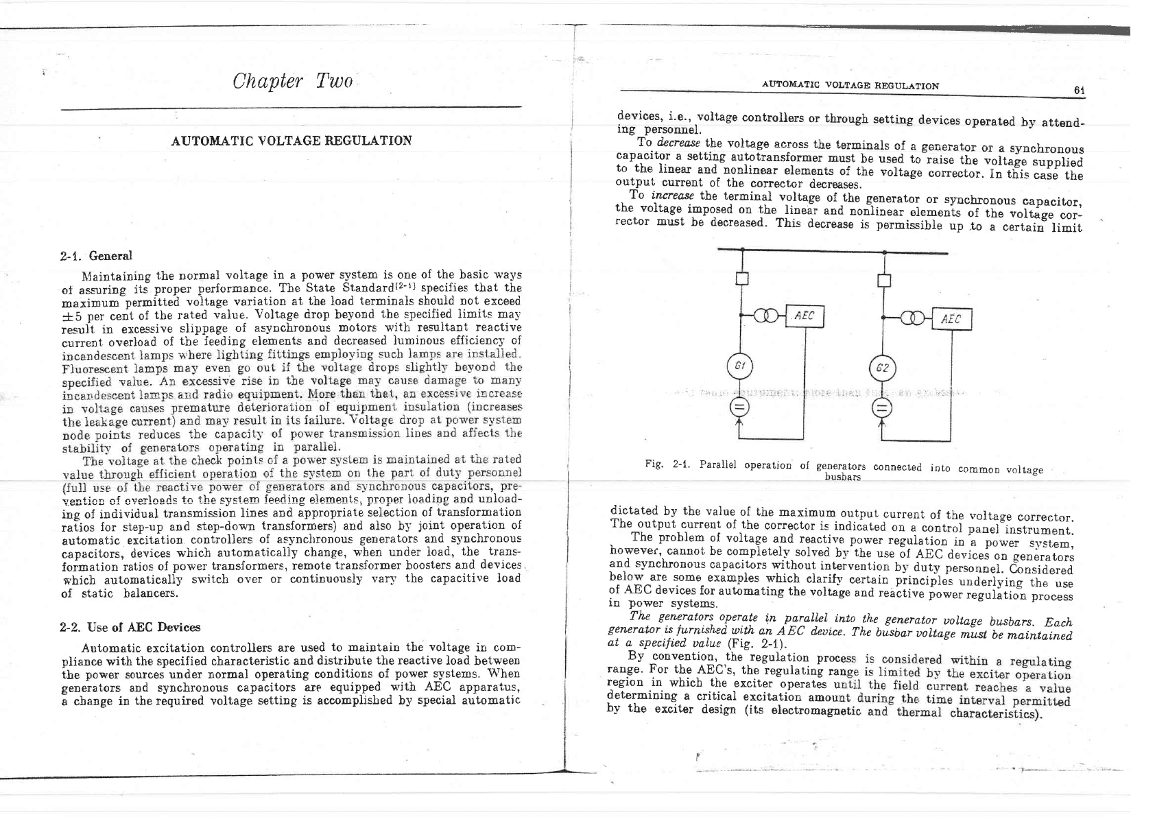
The
generators,
oyergle
in
ryyallel
into_the
generator
uoltage
busbars.
Each
generator
ts
furni'shed
with
an
AEC deuice.
The
bisbar
uoltage
*|,tt-Ut
mai,ntained.
at
a specifi,ed
ualue
(Fig.
2-1).
By
convention,
the
regulation
proc
range. For
the
AEC's,
the
regulating
ra
region
in
which the
exciter
operates
u
determining
a
critical
exeitatibn
amoul
by
the
exciter
design
(its
electromag!