Barzam A.B. Automation in Electrical Power Systems (Системная автоматика)
Подождите немного. Документ загружается.

CEAPEER
T'WO
o tll D--f -- n----d^--
a-
tu.
r\eYlew
({uf
rrr('rr5
1. What is the difference
between
the astatic
and static
characteristics
of
voltage
regt-
lation?
2. What is
current
stabilization. and
cqrr-elt compeusation
in voltage
regulation
devices?
Explain
the
purpose
of each
and
field
of
application.
3.
Hoq' are
the specifie-d reactive }oads
distributed
between
paralleled
geDerators
work-
ing
into
tbe
generatbr
voltage
busbars?
"
4. How ar-e
tbe
specified
ieactive
loads
distributed among
generator-power
transformer
sets
working into
eonimon
busbars? Wby
is
it
Decessary to
olJerve
a
deiinite
distribution
of
reactive loads
among the
generators
and astatic voitage
reguiatorc
under such
operating
conditions?
5.
Expiain
voltage
reguiation
in
power
systems.
Wbf is
it insufficient
to
use AEC
device
solely
for
voltage
reguiation of slnchronous
machines?
-
6. Describe
group
eJcitation regulation
o_f
generators
at
a
multiunit power
station.
Wbat
is
its
purpose
and
possible
application?
.
7.
Expiain
t'lre purpos€
and
possihility
-of
use of automatic voltage
regulators
controlling
the transformation
ratio
of Dower
transformers.
8. Why is it
possibie
to dhange the
voltage }evel
at a node
of a
power
system by
con-
pectlng
lumped_-capacitance banks? Under wbat conditions
should
the
banks
of capacitors
be disconnected?
9.
\4rhat
is
the
purpose
of automatic
force
(capacitor
banks
at tbe receiving end) and
10.
Describe
progranmed
voltage regtl
11,
Erplain
automatic rezulation
of
vol
u'ith utilizition of a
controlied
reactor and <
metbod
as eompared to autornat,ic res"ulation
to change
'"he
oapacitance current
vilue?
Ch,apter
Th,ree
3-1.
General
The
excitation
s}'stems
and
the
field
discirarge
devices
oJ svnchronous
getre-
rators
and
motor*s
are
considered
in
detail
ilG;il"oks
on synchronous
machine
operation'
This
chapter
presents
Tp:
principie-*lescribing
the
development
of
the
above-mentioned
systems
which
as-sure
correct
operation
oJ
automatic
power
system
control
assemblies
and protective
relayinf
;;;i;;;."'
There
are
separare
excitation
systems
in
*,hich
th;;u;pii-
;
exciting
cur_
rent
to
the
field
winding
of
a
sytchronous
-r*iiior
is
Jr'om
"n
irrarpendent
EaY(-Tm A Ttrrl tr ct\r6m-r r^
ElN-iJi
iAi
iu.i{
S Xiji.iifiis
AND
AUTOMATIC
FIELD
DISCEARGE
DEVICES
OF
S}'I{CBiOIVaUS
MACEINES
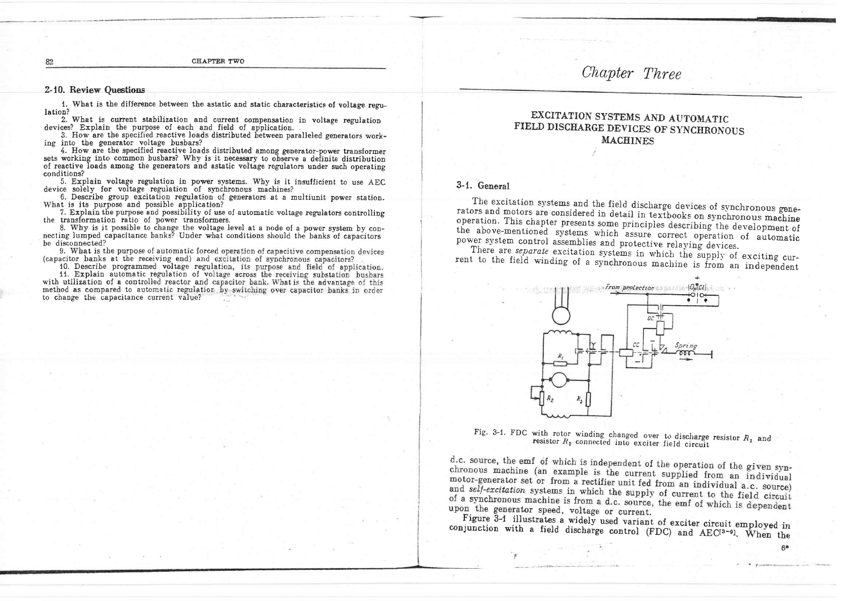
,fmat
ltfutecfton
Fig.
3-1. FDC
witlr
rotor
winding
changed
over
r€sistor
.R,
connected
into
exciter
1o
discirarge
resjstor
.R,
and
Ireld
circuit
Figure
3-1
illustrates
a
widel!
used
oaiiant
of
exciter
r
'6sre
e-r
*ruDr'Jr'rtris
a
wrQely
usec
varlant
of
.exciter
circuit
ernployed
in
conjunction
with
a
field
diseharge
control
irnCl
and
A66r;--s1]
1tr;hen rho
{BQts-s1.
When
the
6.
r
t4?,crl
=Ig

E:KCITATION
SYSTEMS
AND
AUTOMATIC
FDC
DEVICES
85
84
CEAPTER
1IENEE
circuit
is
of
t.he
seif-excitation
type
the continuous
current
generator
is moua-
ted
directly
on
the shatt
of
the
synchronous
gensrator
rotor. If
the
continuous
curuent
generator (exciter)
is driven
by
an indivitiuai
motor suppiied from
the
power
s1'stem,
use is made o{ separate excitation.
To
improve
the
reliability of
excitation systems, the tendencv
is now
to
replace
d.c.
commutator
machines
by
semiconductor
devices.
,g-*:l1t-"-t^:tl |::chfrge
its
fieid.
These
circumstances
have
been
considered
r!
v$qIJrErD
-t
a
uu
z.
^_"'|:""^":t_li::r...
yilh
the
srate
standard
Gosr,
rhe
excitarion
sysrems
must
eiisure
an
exci'ua'r,ion
forcing
muitipiiciiy
factor
of
not
less
than
i to"renerernrs
and
syucrlrono.us
c-apacitors,
whiie
the
rate
of
excitation
rise
;i;;f;"ffff;
]ess
than
2 unit,s
of
-ercitation/second.
The
fieid
djschar-ge
control (FDC)
di.sconnects
the
excitation
ri.rcuit
of
the
rotor
winding
from
the
d.c,.
source
or another
method
i.
"r"a
io-*oo
the
current
fios'
in
the
rotor
circuit,
such
as
the
cuttinf
out
of -ssnissuductor
devices.
The
action
of
the
FDC
is
more
efJective
*[r"-tn"
stator
emf quickit
d*;;;
the
value
at
which
arc
self-extinguishiog_occ,rrs
il
;il;t"il-*li.
to
the
srator
insulation'
Self-extinguishing
of
irc
uruiitl'
o.r"".
at
b00
volts
oi
less.
The
resi-
dual
emf
due
to
thJ
residuil
magretizaiion
does
not
exceed
ls0-200
volts-
The
functioning
of the
FDC
is
co'mpulsory
when
fauits
o"r,r,
irrride
the
gene-
rator'
The generg-tol
operation
is
allowed
witUout
exiitation
during
self-syn-
chronization
until
the generator
reaches..th.e
hlpo-.yochronous
speed
and
the
Igtol
winding
is
changed
over
from
the
discharliog
iesistance
to
carry
the
full
field
current.
Disconnection
of the Fl^)C ,].r.,ri.., ?,
tor
result*io
".yo.tronous
tperation
witir
resperr
rJrT.H;1tJ:1.::#"
senera-
-
If
reserve
power
is
avaiiable
in-a power
f;.t"*,
the'generriot.
which
lose
their
excitation
are
automatically'
did;;;;tea""s
the
b1o-cking
c-ontacts
of the
FDC
device
send
,
triP
signal
i9
tle
outpui-t.l"y--
oi-tn.
pioi"ction
s'srem.
With-a
shortage
of
a3tive
p-o*nr
in
|he
por,-*
ri=ten;'r,he
tnrbogei;;ffif'";;t
be.allowed
to
operate
v'ithout
excitation
for
some
time
(1s
6-30;;;r;;i
provided
the
active
load_
of the
generator-in
..i,rr"hroooo=
Jpur.ii"n
is
reduced
to
a value
approximatelv
40 pEr
cent
of the
rating
so that
the
generator
is
protected
against
current
overioading.
\vith
the
TGv--200
(TrB-200;
aia
rc\r-300_-(TrB-300)
rurbogeuerators
emplgrling^gas-discharge
tube
exciiation
and
rhe
TVv
ifgBL'{oili,
rvrt
-2aa-z
and
TV\t--320-2
cran4Iaf npc -.]ri^'L
--,^-:+,-.4: --
roa*iri^-^ _,-6^:"::.:,::"-:X"l
ubc
err{,llarlon
energ},
Irom
-semjconductor
rvvlrrrsr;t
ulJtrrdLru!
ur tlle
rIJu
ogvlces
and
arc
extinction
ma-v
causg
overvol-
tages
dangerous
to
the
insulation
materials
of
rhe
;";;;.-\ilt;d;lirectivesrs-lj
prescribe
the
use
of.discharges
operaring
at 2.4
u1;
[i..2
kv;;;i'tl
protec.r
the
rotor
iasuiation
against
rupiures.
To
prevent
dangerous
bverload
of rotors
having
forcecl
winding
cooling,
their
excitation
control
devices
are
furnished
rvith"
r iot"ing-lititrr.
In
FDC
devices
which
su'itch
the
rotor
oindiog.
t;-
;;;..]r*rg.
resistor
(Fig'
3-1),
the
stored
electromagnetic
energi'ls
aisiipited
in
the
1irm
of
heat
by
resistor
ft/. The
greater
this
reiist?ng.e,t[e
rrigtrer
ii..
"oii*g;"*;ors
the
rotor
terninals
and
the
quicker
the
field
discharge
iro"*r..
The
p;t;ir.iur*
voltase
across
the
rotor
terminals-d-epencls
on
the
iisuiation
effectiven;*
U;;"iIrTf;;
resistance
is
four-
to
five-fold
of the
rotor
u.inding
v'hen
in
the
warmed
state-
Resistance
R2 is
about
tr0-fold
the
resistance
of tle
exciter
fieid
coil
again
in
the
warmed
ilondition.
\47hen
the.generator^is
idling
tire
field
discharge
time
i-s
S
Lo
T
s.
The
rotor
current
and
the
value
of
emf
drop
foilows
the
expEnentiai
curve
(Fig.
B€).
Th;
s
t
t
0
0.5
1.0
t.5
Fic.
3-2.
Determining
tbe
mean
rate of
excitation
rise
Fig. 3-3. Changes
in
generator voltage after
operat,ion
of FDC
according
to
Fig.
3-1
(no-
]oad
runnins):
troc is
FDC
operating
time
\'
\
CE.A.PTER
TEREE
EXCITA?TON
SYSTE,MS
AND
AUTOMArIC
FDC
DE\rICES
differential
equation
describing
the
rotor
current change
has
the
L
#i-
(ftr
1-
r) i:
g
-
?
(FI*t)
i:
Ioe
r'
cunent in
the
rotor
winding
inductance
and
resistance
of the
rotor
winding
resistance
s'hich
the
FDC
device
connects to
the
terminals
T,bi"k
damage
by
reverse-cument
circuit
breakers
with ono-chnr orrrnnn*i^
reeiosure.
'i'he
auxiiiary
generator
has
an
AEc
d;;i",
*ita
"";;ffffiil;;
an
electtomagnetic
volta-ge
corrector.
-
GaS<Ilsclnrge
tube
egci,ter
wi,th
a seri.p,s-rnntzpnlorl rsnsn{^*^-rc-a1
diagram
variant
for
this
excirer
is showa
i"
ii[::
d'.\;L";"::;;*:;J".lJ#Xil
hence
g'here
r
-
L,r:
frr:
form
(3-1)
(3_2)
rotor
winding
-With -the
gas-discharge
tube
or
thyristor
excitation,
the
fieid
is
effectiveiv
and
rapidlv
discharged
(suppressed)
b1,
inver-ting
the
exciter
and forcing
ri-"f-
taneouslr
the
excitation
to the
upper
critical
value
dictated
b1'
the
rotor wind-
ing
insulation.
The field
discharge time
approaohe-q
here the
theoreticai
value.
3-2.
Excit"ers
Using
Gas-Discharge
Tubes
, ,i',.
.
and Thyristors
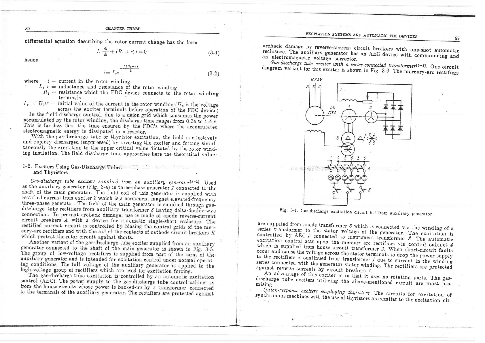
Gas-disclwrge
tube
ezci.ters
suppti.cd
from
a.n
autili.arg
generatorls-zl.
Used
a,s t-he
auxiliary generator
(Fig.
3-11 is three-phase
gener"io.
Z
connected
to
the
shaft
of
tbe
main generator.
The
field
coil
oi
tnis
generator
is supplied
with
rectified
current
from
exciter 2
which
is a
permanent--magnet
elevatr"Oltr.qrr"orii
three-phase
generator.
The
field
of
the
main
senerator ii suonlied th".,.'.,oh or.-
discharse
tube
rectifiers
from auxiliarv trans"fnrmo'-4 ho-,;.i.Ii.rt"--l^-,,r.-r;-::;
'
Gasdischar-ge
exciiaiion
circuit
fad
from
aux'iary
generaror
are
supplied
from
anode
transformer
6
which
is
eonnecl,ed
via
the
winding
of
a
series
transformeJ
to
the
stato.
*'olt^g,
;i'
;[.-"generator.
T]re
excitation
is
conirolled
b1'
AEc
5
connect*d
to
insirument-transformer
J.
Tiie
automatic
excitation
control
acts
upon
the
mercur],_arc
rectifiers
via
eontrol
cabinet
4
which
is
supplied
from
hius.
circuit
transformer
2.
when
short-circuit
fauits
occur
arrd
cause
the
voltag*
*"tori
the
siator
tliljn*i,
to
drop
the
power
supply
to
the
rectifiers
i-t
contiuir.d
f.;;
transform",
id,r.
to
current
in
the
winding
-serjes
connected
with
the
gro*."L,
shtor
winding.
Th,
;;;ifi".r"".,
protected
against
reverse
currents
by
circuit
;;;k#";-'""
An
advantase
of
this
excit;;lr-in
thai
it'uses.no
rorating
parts.
The
gas_
*,tt1?1-t
tube-excit"t.
"tit-iri-og
til
uroo"--lo?o*"a
circuft^"."
*ort,
pro-
^-.-9:::r-respot&e
exciters
employing^
th.yri.stors.
The
circuits
for
excitation
of
synchroriorrs
machines
with
thb
uie
oi
thi,riiior,
.r*-ri*ilar
to
the
excitation
cir_
t{.sky

CTIAP{TtsR
TIIRE.E
u'CTTA"ION
SYSTEUS
AND AI}TOTT.ATIC
TDC
DEVICES
89
cuits
utilizing
controlled
gas-discharge
devices'
shows
a
block
diagran
of
the th-vristor
exciter
bogenerator
plant-
for
synchronous
661613[8-ar
B5'*'ay
of illustration
Fig.
3-7
developed
at
the
Kharkov
tur-
s
-61.
fnn.AIC
device
q,/
dultlrorlt
getTeroior
fDC
device
When the motor
is
started the thyristor
is
short-circuited to
starting resistor
.R,
Due to the
effect of
the
induction
torgue,
the
motor spoeds up to
a
hypo-
sYt*"onous
speed. The current measu-
rements
in
the
.R, circuit
are taken
from the starting
resistor
protection
uuit
S,RP
which
measures
the
voltage
drop
across the voltage
transmitter
VT,
tb.e
voltage
being
taken
from the
terminais
of
a saturable
inductor. The
SRP
unit
acts
on
the
controi
pulse
shaping
unit P,9[i. When the
hypo-
synchronous
speed has
been
reached,
the .9^RP
unit
cuts off
thyristors
ThI
and TIyZ and with the
aid
of
the PSU
triggers
the thyristor
unit
into
conduc-
tion,
thus
feeding
the
field
current
from the
supply
transformer
to the
rotor v'inding.
If
the motor
is at fault
and
its
protection
is
functioning, a
sig-
nal
is ,sent
f,o
the
S,RP unit s'hich
makesthi,'iistors
Thi and
Th2 conduci
and
simuitaneousll: cut
off
the thyris-
tor
unit.
Tbus
the
field
is discharged
and
the
motor is
switched to
the start-
ing duty.
Similariy,
the
^SfiP
unit
ma-v
be used
to
change the
st'nchronous
mo-
tor to
operation
with
removed excita-
tion
and
discharged fieid
for
subse-
quetrt
self-s_vnchronization
of
the
motor
-after
recovery
of
the
stator
terminal
voltage.
The
forcing
iimiter
unit
FlU
is
connected
to
the
rotor winding
circuit
via
d.c.
transformerc
DCT. When
the
current
fiol1' in
the
rotor
winding
circuit
exceeds
the
rated
value
the
FLU
is
nouconductive.
The
rotor winding
via thyristor
sp'itches
fft.i
and
Tht-
Fig.
3-6. Gas-discbarge
excitation
circuit
with
series connection
of supplS' transfornrer
into
generator
stator circ.uit
Fig. 3-5.
Gas-discharge
excitation device
energized from
auxiliary
generator
iounted
on
the
main
generator
shaft'
e
-
contacts
of
anode
re"ersgurrent circuit
breakers.
with
oneshot
reclosure;
Du and
ji
-
di6ch-aryet-'aiii-iorie"f-ti-161une
resrstor.
to
protect
.agains.t
ov.ervoitages.which
mav
i,t"ut-*ften-iic
ii-lnieiiupieC
in
valves or
r*'hen
'irnode
circuit
breakers
colDe
into
actiott;
Ii
-
conracror
coni"if
iu-tiine
in
rCsistor R
for
Gtarting b-l
self'synchronization
metbod
acts
upon
the
control unit
CD
which
in turn
reduces
the current
in
the
fieid
,*
+1"
$s
-E€
'ets
bi
F,
FE+
e:.I
:\\
iJ\;
i'e
t
______-J
---
int
power
suppl-v
to-
the
-thyristor
.onnr."tiln
transfoimer
through
rectifier
CBAPTER
TEREE
sequence
of
oPerations
is
performed
by
the
sc
unit
whioh
responds
to the
stator
-ra"
of
a biower
controlled
by
suppl-v
unit
is from
a
step-down
doubie-wye
bridges.
To
cool
the_
assembll-,
use
,is
unit
,SU
with
the aid. oI contacLo!
K.
Fig.
Block
diagram
of
thyristor
excitation
slstem
E)ICITATION SYSTEDIS
AND AUTOMATIC
FDC DEVICES
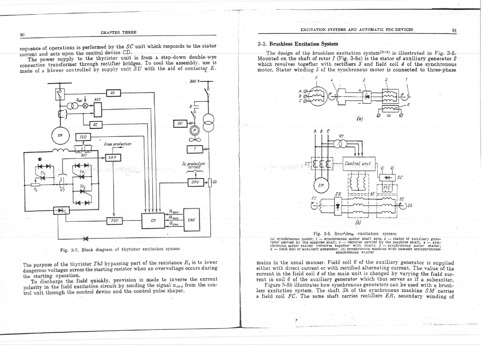
Brushless
Excitation
Syste,rn
Mounted
on
the
shaft
of
rotor
/
(Fig.
3-8a)
is
the
stator
of
auxiiiary
generator
2
which revolves
togefher
u'ith rectifiers
3 and
field
coil
4
of
the synchronous
motor. Stator winding
5
of
the synchronous motor
is connected
to three-phase
Cont,-.ol
uot/
t
.9f
l4
i-f.
I
T
I
L
_J
L
_J
{b)
Fig.
3-8.
Brus\leq
excitation system
(a)
synchronous
motor;
J
-
g.vnchronous
motor
sbaft
axis;
I
-
stator of auxiliar-v-
gene-
rator
carried by the
machine
shaft;
J
-
rectifier carried by the
macbine shaft:
4
-
syn-
ehronous
motor
exciter
(reyolves
together
with
shaft); J
-
synchronous
motor
stator;
6
-
field
coil
of auxiliary
ceneratorsijlirT;)flJ"li:-q
macbine with
cascade asynchronoue-
mains in
the
usual
manner. Field
coil
6 of
the
auxiliary
generator
is
supplied
either
with direct current
or
with
rectified
alternating
current.
The
value
of
the
current
in
the field
coil
4
of
the main
unit is changed
by
varying
the
field
cur-
rent
in
coi] 6 of
'the
auxil.iary
generator
n'hic.h
thus
serves
as
if
a subexciter.
Figure
3-8b
illustrates how
synchronous
generators
can
be used
s'ith
a
brush-
less
eicitation
system.
The
shaft Sia
of
the s1'nchronous
machine
SIW'
carries
a field
coil FC.
Ttre same shaft
carries
rectifiers ER,
secondary
winding
of
A
B
;ing
part
of
the
resistance
.R.
is
to
}ower
listof
when
an
overvoltage
occurs
during
rvision
is
made
to
inverse
the current
ry
sending
the
signai
a;,,o
from
the con-
I
the
control
Pulse
shaPer.
CEAPTER
,IEREE
93
92
asYlchronous
stator
winding
of
auxiliary-synghronous
exciter
ion: crrnr.hrionous exciter
(EFC\
is
supplied
fron
EXCITATION
SYSTRTI{S
AND
.AUTOMATIC
TDC
DEVICES
erator
ilFG
is driven
by
the
turbogenerator shaft
on whicb
the
rotor of
maln
gensraf,or
ilorling
onup
To
storage
batlery
Io backup
etciter
forctng
oroup
___rl
ii
I
I
I
rl
l_______
-------r
I
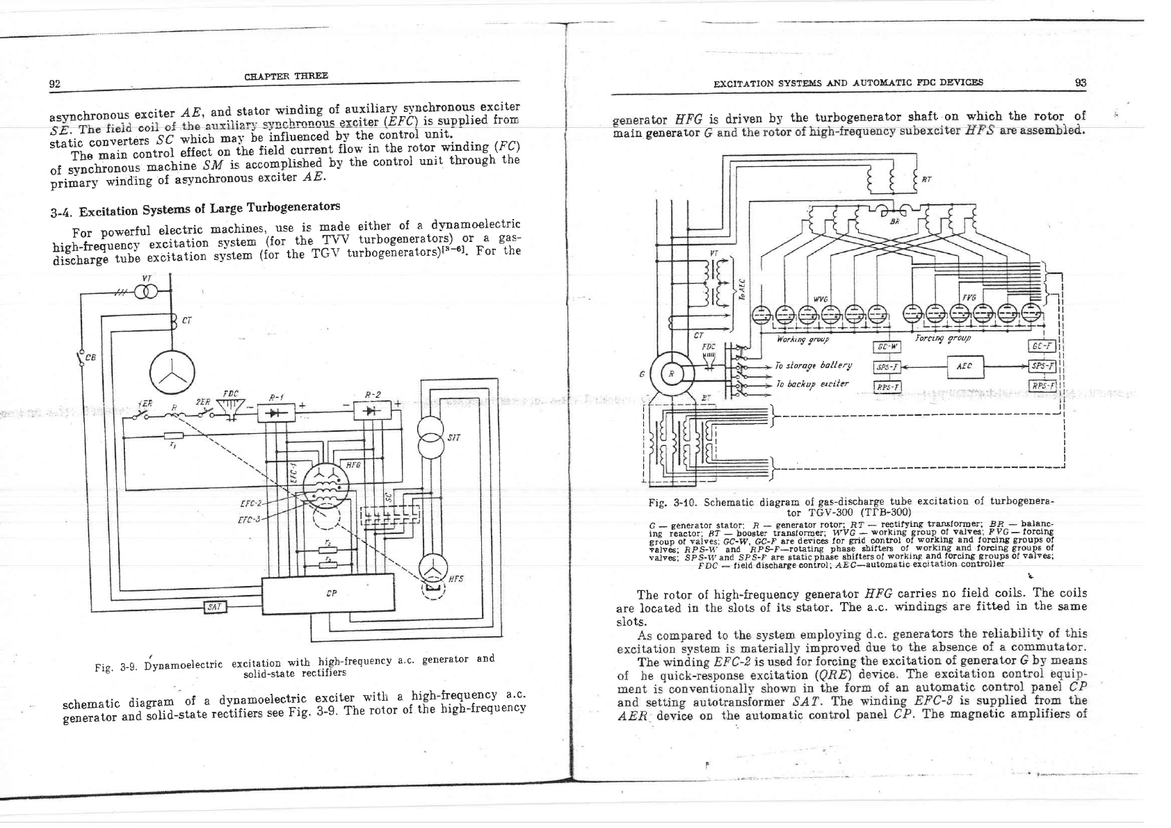
Fig. 3-10.
Schematic diagram
of
gas-dischlrgg t_q!g
excitation of
turbogenera-
tor TGV-300
(TI-B-30U)
G
-
generator
stator;
.R
*
generator
rotor:--Rf
-
rectifying
transformer;
!3--
balanc-
ing i'eactor; R?
-
bboet€r
tiaruforroer;
H'VG
-
workilt*
group
ol valves;
FyG-forcrng-
gr"oup
ot
vaives:
GC-W, GC;F
are
derices lor
grid.
control
ol
working and
torcing
groups
of
iifs&;
FpS-ti
and RPs-F-rotating
phast
sbifters
o.f
.
working and
forcing
gloups
of
"at"es;
bp-c-t.T'and
SPs-F
are staticphaie
shiftersof
working and
forcing
groups
of
Talves;
FDC
-
f
ield
diseharge
controll AEg-autopatic
excttalron
contFoller
L
The
rotor
of
high-frequency
generator HFG
carries
no
field
coils.
The ooils
are Iocated
in
the
ilots of its
stator.
The
a.c.
windings
are fitted
in
the
same
siots.
exciter
AE,
ard
i#;,Jil#=r;;";--se
v,hich
ma1.
ie
influenced
by
the contror
unit.
The
main
"oo#Jt
;lf.;t
*
iUt
litta
curreut
fiow
in
the
rotor
winding
(FC)
of
svnchronous
machine
^!M
is
acconpiish."g
irv
ihe
controi
uui'r,
^r,hrough .uhe
ririii'o'*i"J*g
of
as-vnchronous
exciter
AE'
3-4.
Exeitation
Systems
of
Large
Turbogenerators
For
powerful
electric
machines'
use
-is ry99
either
of
a
dynamoelectric
high-frequency
excitation
system
(for
the
T\/a/
turbosenerators)
or
a
gas-
discharge
tube
exoitation
slisteJtior-trre
rGv
turbogeierators)ts'-61.
For
the
Fig.
3-e.
Jvnamoele"uic
*:llil'-"r?";t'*"Xiil;Jresuencv
a'c'
generator
and
schematic
diagram
of
a
dynamoelectric
exciter
with
a
high-frequency
a'c'
il;;"i;;-;d:;itd-siate
r.itifirr,
-"ee
Fig.
3-9'
The
rotor
of
the
high-frequencv
I
CEAPTER
TEN.EE
(3-3)
Accord.ing
to the
above=mentioned
facts
the field
discharge
time
has
its
minimum
*f,"o
the energy
accumulated
in
the rotor
winding
is
dissipated
at
EXCITATION
SYSfEMS AND AUTOMASIC
FDC
DE\4ICES
the maximum
rate
durin
rL^
uue eriod
^r,he
FDC
device aets. In this
case
95
-di
L+ Rti,:-Ur",
dt
(34)
the
generator
assures
additional
excitation
current
forcing
of
the m_ain
genera-
tor
6
due
to
a
free
current
arisiug
in
the
rotor circuit
in case
of
a short-circuit
at
the stator
side.
e
caused
by
free current
flou'ing
in
the
rnts
in
Lhe
EFC-Z
and
EFC-?
v'indings,
rrallel
rx'ith
aII
these w-inriings.
circuit
is
shown
in
the diagram of
llf-excitation.
The
rotor
current
is con-
[e
grid
control
device.
The
rotor
recejves
rups
of
the valve*s.
Under
normal
operating
per
eent)
is
from
rire
woiking
group
arid
the additionai
supply-
(30
to
40
per
cent),
from
the
forcing
group
of
valves-
In
case of
a short-iiriuli
in
the
generator stator
circuit,
the
forcing
group
beco-
mes fully
conductive
q'ith
a
resultant
increase
in
the rotor
current
to
its
per-
mitted
value.
?
q
Fi^l.l T.rica}'qrrra hv Tlainn Grid Arrfnmatie.
u-qJ.
I IElu
stsvusr6v
gJ
Devices
and
by
Changing
the
Field
Coil
Supply
to
Inverter
OPeration
Condittoru
for
tfu
qu.ickest
lield
disch.arge.
The
field
discharge
occurs
most
rrpiaf"o-*L"o
d"ti"g
tie entire-
field
dischirging
period, i.e.,
the
time
interval
when
the
current
iu"the
rotor
of
the s-vnchronouJmachine
varies
from
the initial
;;I",
lr-tl-rrt"[3-7],
the
stator
u'inding-
termina].
vol_tage
remains.constant
and
.q""1
td
ttre
maximum
value
p_ermitted
!i1 !he-insuJation
strength'
-'
L*t
the
value of
resistance'RL
in
the FDC
(Fig.
3-1)
be
far
above
the
value
of
rotor
*,inding
resistance
r. The
differential
equation
describing
the fieid
discharge
ptoce*i
in
such
a
device
is as
folloq's
L+*.R,i:
o
In
this
instance
time
where
U-r"
is
the voltage across
the terninals
of
the
rotor winding
in
the
excitation
forcing mode.
From equation
(34)
it
is
clear
that
the
best
field
discharge
conditions
in
accordance
vith
the
diagram
in
Fig. 3-1 are obtained when the
FDC
uses resistor
,R-I
v'hose resistance
varies
iuversely
to
the
current
-flow-
ing
through
it.
Expression
(3-4)
determines
the linear dependence
of
the
current
decrease
q'i.th
time
;- T
Umax
,
t-r0--r
o
tbe
current
falls
to
JTL
Lnrln:
I
o71-
u
max
which
is
t,he minimum
possibie
time.
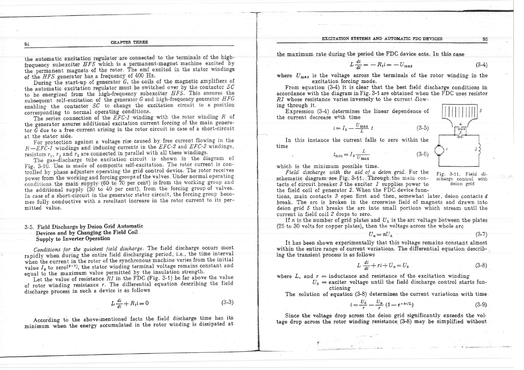
Fi.eld
dischorge
with,_tfu
^atd
ol a
dci.on
grid.
For
the
Fig.
B-11.
Fieid
di-
scliematle
d14gram.see.Fig.
3-Il; fhrough,the
illai'j
cori-
s*fr".g,,
canrroi rvith
tacts
of circuit breaker
3
the
exciter
-I
supplies
power
to
deion
grid
the
field coil of
generator 2.
When the
FDC device
func-
tions,
main contacts
3
open first and
"uhen,
somew-hat }a'r,er, deion
contacis
4
break.
The
arc is
broken
in
the
crosswise
field of magnets
and
drawn into
deion
grid
5
tirat
breaks
the
arc
into small
portions
which
stream
until
the
^------r:- l:-ll ^-:l
r}
-l---^ 4^ -^--
OU.fl'eflt
IIl llelU V9LL
I' UIUP5
r,U ZBIU.
If
n
is
the
number of
grid
plates
and
Uo
is the
arc
voltase
b'etween
the
piates
(2,5
to
-30
volts
for
copper
plates),
then the
voltage
ae.ross
the
qrhole
arc
Uo:t{in
/a t\
\d-
|
,,
It
has been shown
experimentaliy
that this voltage
remains
constant
almost
within
the
entire
range
of current
variations.
The differential equation
describ-
ing the transient
process
is
as
foliows
-di
L;+riiU"-Uo
where
tr,
and
r
:
inductance and resistance
of the
excitation winding
Uo
:
exciter
voltage
until
the
field discharge
controi
starts
fun-
ctioning
The soiution
of eguation
(&8)
determines the current variations
with
time
i:+-+
{1-e-ttr1
(3-5)
zero
within
the
(&6)
(s-8)
(3-e)
Since
the
voltage
drop
across
the deion
grid
significantly
exceeds
the
vol-
tage
drop
across
the
rotor
winding
resistance
(&8)
may
be
simplified
without
t
CEAPTER
TEREE
ilil1||t!lrl
IrJ320
.r
1flilil|l||l
T .= 8fllA
The
structure
of
(3-11) is
the same
as
tirat of
(34).
It,
determines
the condi-
tions
under
w.]rich
the
minimum
possibie
time
of
field
discharge
may be
attai-
ned.
Therefore,
ti.
-iltla
discharfe
time
can
be
brought
close
.tt iF
ninimum
;il;-
#'pr"rrlrri'riroo.i"g
rhe
pErformance
characteristics
of
the
field
dischar-
eJ'it"i".'fuirrished
rvitir
a
deion
grid'
(3-10)
(3-11)
ilillfitl
Fig.
V14.
Field discharg€
control
unit
with
deion
grid
desigued
for beavy
currents
r
-
Bt8el
plate:
g
-
current
lnput
terminals;
t
-
main
movable
sontactS;
4.; auxiliary
ito"ali"-
finiabG:
s--
cross'tietd
extinglishilg
coiisl
6
:
g-9
.extinguisbing
borns;
z
-
deion
c"idj
s
-
eteel
*XL,rr;*?rTl
""8rffi
jrr"Gt"ot",-trero
corr;
rr
-
bvpa*s
7-2076
P
Q0['
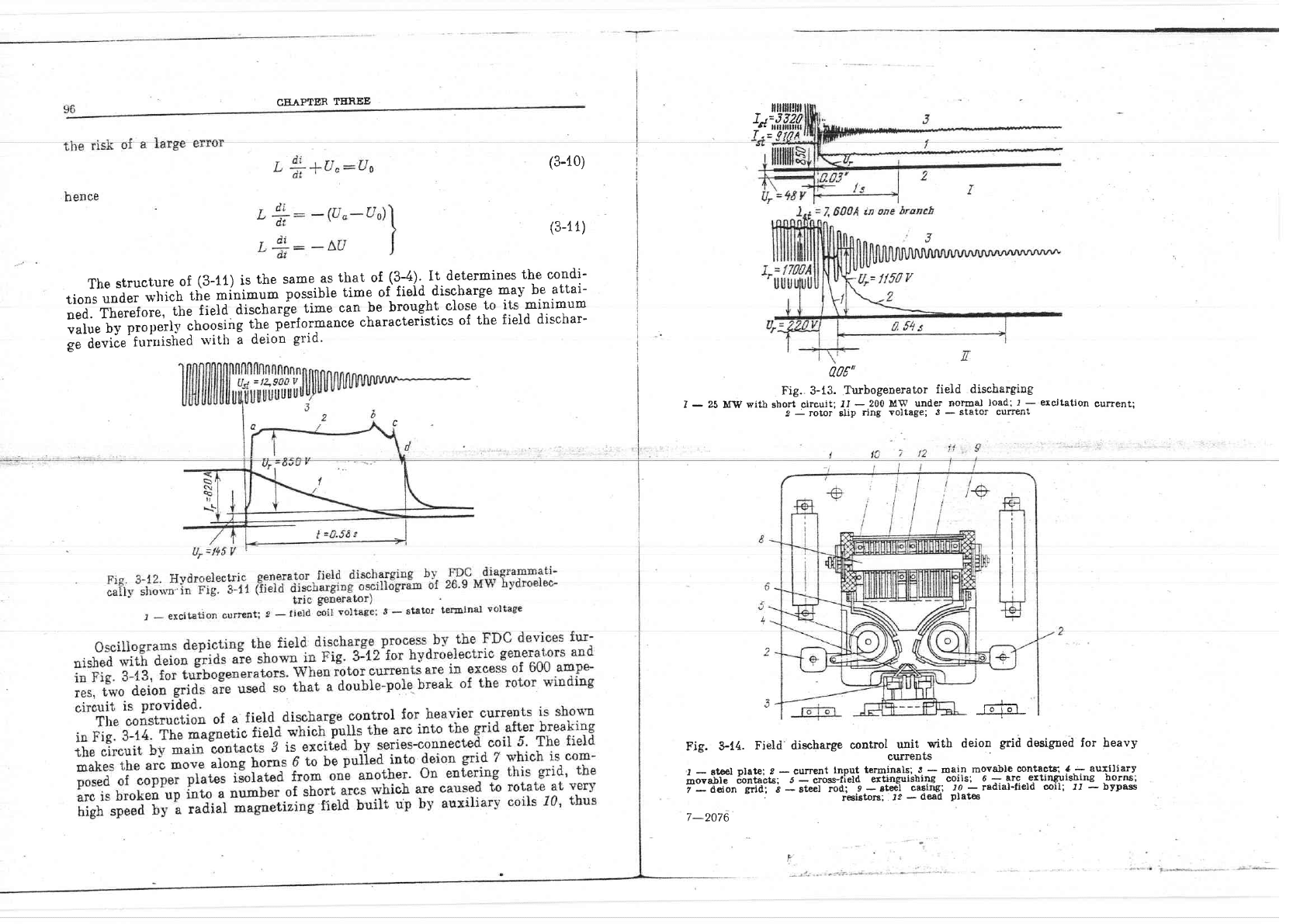
Fig. 3-13.
Turbogenerator
fieid
discharging
I
-
23
lfw
witb short circuit;
lI
-
200 MW
under
normal
losd:
I
-
ercitation
current'
I
-
rotor'sllp
ring
voltage;
J
-
stator culTent
lo 101
.--1_-
CIIAPTER
TIIREE
YtusJ !J
Pqeo
itrstaDt
the arc
is extiDguished'-
,.,- - r,-r, -^-.-^r -^^ !.;-
r
'rhe
tlifferential
equatiol that describes
tbe
field
discharge process
rs
For
the sohemaiic
diagram of
the field di_scharge coDtrol see
Fig.
$15.
I
f"rriJs
to
aIIo*'
for
starting
by
the
self-slnchronizing
method
(see
Chapter
7).
Fi, e-{< l-nnfrnl
nf I'fl-C
rrnit frrrniqhed urif.h c dpinn srid
!
IE' V-^u'
vvuwrvr
.
o
-Eain
contect:
b-e-bloclrlngcontacts;1-4-contactors;
Er-^regulating rheostatl
h.
- power
limiting
r€sistor
cut
in
after
tbe
main
contact of
a
FDC
open6;_-4r
-
series
iiiistoi-;na
,--cdntactor
(these
are
installed
to allos
generator parallelling
b-r
the
self-synchronizing
metbod)
I
rll
Dr€vetrii[goveI}reatiDgandbur.ningoIthe-p!g!9g!qL4esistoIJ7whichpro.|c.ry.alcrectilje
fides by:fass
lor
the irldividual seitions
ol i@
--^ i- ^-+i---i.l"^,1
The
circuit
ernlloyed by
-the
FDC
with
deioD grid
etrvisag_es
inse ioD !l 8
|
,
in
rpsistance
ir
parallel
with
the ercitation wiadhg ol a
syachronous
macbiue
I
L
i+ir:
-A^^,
(3-L2)
EXCITATIO].i
SYSTEMS
AND
AUToTTATIC
FDc
DEvIcEs
If
the voltage
drop
across
the
resistance
of
the
rotor
as
compared
to
the
I't
E
Fig'
3-16.
Hydro-electric
gererator
field
discbarging
under
no-Ioad
conditjons
x-hel
using.-gps-discharg_e
tube.exeitatior (t:re-ge-reretor
re'!ing
is
i05
lvf$,')
voltage
value
U'r",
ma]'
be
neglected,
then (3-12)
takes the
form
L
+:
-
umax
(3-13)
ancl
becomes simiiar to (34)
which
i-s
the
condition decisive
for the
quiekest
fieid disc,barge.
Fiarrra 1-44 oh^tt,c o ftrniaol ^.^ill ^f +L^ +:^lJ J:-^L
e
rv ouvYrD
q
u-rlJrvqr
uDvrrru6adu
Lrr
LlLtt
IttrIu
uIDUIlaIg-c
Progess.
3-6. Conclusions
The
field discharge
circuit
must
enable
the
machi:re to
connect
by
the
self-
synchronizing
method.
.
4.
Pro*ising
is
the
dggign_
of exciters
s'ith
a
brushless excitation
system
as
it materially
improves
reliability.
.j*
\
s
\6
s
e

CHAPTER
T.HREE
r@*i
I
n,n€I?
1,/7
O^.o is-t\e
amplitude
valD6 of
.th€
ba.iBUE
vo.ltage
acmss the st{tor totmi-
;"""if,';$;;i";i;ii"i
it"iJ-ai"mge
timi.may
be
attaiDed.
I
r:frt' 105:+.4.6:4.48
g.
Usine
the data
of
the
foregoing
example.
calcuiate tbe
minimun
p_ossible
f^ie,l!;
discharge
ii6e
when
constant
voltaEe
equai
.to-ibe
value oJ tbe
test
voltagl, Ur"st: 3,500
""iii.
6urfG
maintained
across
the-rotor
winding
terminals
during
the
discharging
process.
Solution.
In
compliance
with
(3-6)
t
fmrn:10
#-
u
teet
lmtu:2,050ffi
is
about
o'5s
EXCITATION
SYSTE]YIS AND
AUTOMATIC
FDC
DEI/ICAS
10. Using
the data
given
in erample
3-9,
deterrlin-e
the fieid
is made
of
a
FnC
device
t'aving
a deion-grid
composed of
75
plates-
the
plates
be
equal
to
30
volts.
'solution
1.'We
first
determine
the
voltage
across
the arc
in
field
discharge
control
has
tripped
U
o:30'75:2,250Y
2.
a:rd
',hen
in
acccrdance
r.l'itl
($'11)
r
"'
"::
'rdltr
Li:
-(Uo-Uo):
-
(2
2i'0-345\
L
+:
_
1,905
tlt
bence
. ,
L
^^=^
0.806
n oc_
.
r:
I0Tf
I,uor,
-1105:u.ou
b
10.
What is
the
difference
between
tbe
thyristor
excitation systeznF
ind the
excitation
systems
utilizing
gas-discharge tubes?
11.
What
is
tirl-;;;;;;;ft
p"i""ipt.
of
tbe
brushless
ercitation
svstem?
12.
Wirat is
the
puipos.
oitfie forded
excitation
limiter
us€d
in
excitation
control
dev-
ices?
101
;;;i;-ggug;:l"Jrlti"dit":'J?i,,lit'il,'"til1;-"".
r1ri1c,g"'-r"-.Tr*:*
| ..,
:p--
v
=:t":z=#::'05
*rilgiiri'"'"ii*
1,1
a
las-discirarge,ture
oL
ltrvrj-lfrjxliter
-with
si'ultaneous
I
aDd
4.8
,_ ,^.
4.8
,
"
, , -
3'7.
Review
QuestiotrE
rn
of
synchronous
machines'.What
is
the dif-
ercitation
and
selt-excitation.
systems?.
h
various
excitation
systems
when
the
stator
: droops?
ge
ratdd
turbogenerators'.
- -.
lttiiliog
tLe
tiansfer
field
discbarge,qt?:::'
ntric,
gis-aischarge
tube
and
deion
grid
prtn-
ciples?
5.
what
are
the
cooditions
for
obtaining
tbe
minjmum
field
discbarge
time?
wbat
are
the
specific
feailres
encounrered
t;lH^ffrtr"rio"
or-"
lGia-aiscuarge
unit
using
deion
'ube
excitation
circuit's?
How
is
the
ercitation
curv-arc
t""iiii"i
forcing
group
is
available?
i.*ffii
;i
tbt
excitatidn
lircuit
wben
use
is
rlts.
tiioo
d"."tibing
tlie
field
discharge
prooess
rs
i
-
loe'Lllt|--'J
Here
L
L
ar:w=il4lr
For
tbe
erample
under
consideration
k:L:4
f
discharge
time
s'ben
use
Let
tle voltase
between
the deion
grid*
after the
and
L
_*
o.&9:4.8
,
;:':
T:16T-=
time
it
takes
to
complete
the
field
discharge
process
T
r
16
L:----
^7'
-
-
h-| 1
rr
where
the
Dotor
winding
curr€nt
i,
corresponds
to
the
residual
voltage
Ut"'
at
which
extinguishes
itself
i,
:
(Jr",
Is
V2
U*."
2.
The