Bayer R.G. Mechanical Wear Fundamentals and Testing, Revised and Expanded
Подождите немного. Документ загружается.

3.4. REPEATED-CYCLE DEFO RMATION MECHANISMS
Repeated-cycle deformation mechanisms are wear mechanisms that require repeated
cycles of deformation. There are a number of these mechanisms. Some of these mechan-
isms involve progressive deform ation processes, like creep, compression set, and subsur-
face flow. However, these are usually limited to particular types of materials in specific
wear situations. The more general ones, surfa ce fatigue, delamination, and ratcheting
involve fatigue-like or fatigue processes. Such processes involve the accumulation of plas-
tic strain, which ultimately leads to the nucleation and propagation of cracks or fracture,
which is similar to conventional fatigue. Micrographs of wear scars associated with these
common forms are shown in Figs. 3.24, 3.25, 3.27 and 3.30–3.32. Examples of creep and
subsurface flow are shown in Fig. 3.26. In general, the severity of these mechanisms is pro-
portional to some power, often high, of the ratio of an operating stress to a strength prop-
erty of the material, such as contact pressure to compressive yield stress. The exact form
depends on material and wear mechanism. As a class, repeated-cycle deformation mechan-
isms are not limited to a particular type of motion. They can occur as a result of sliding,
rolling, or impact. They are also not limited to contact between two bodies but can occur
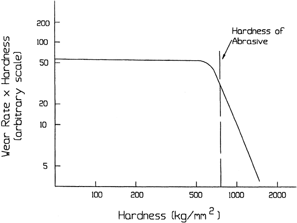
as a result of contact between surface and abrasive particles. However, they only are
important in the latter case when the surface is harder than the particle.
Surface fatigue is a generic term used for repeated-cycle deformation wear mechan-
isms that result from fatigue processes, which occur on and below the surface of contact.
These processes result in the formation of cracks and crack networks on and below the
surface and in deformed material. Such processes can also result in the formation of pits.
Examples of these features are shown in Figs. 3.24, 3.25, 3.27 and 3.30–3.32. Delamination
is a particular form of surface fatigue, which is related to the accumulation of
Figure 3.22 Transition in wear behavior when the wearing material becomes harder than the abra-
sive. (From Ref. 177.)
Copyright 2004 by Marcel Dekker, Inc. All Rights Reserved.
dislocations in a narrow band below the surface. This type of wear is illustrated in Fig. 3.27.
Ratcheting is another particular form of repeated-cycle deformation wear that is based
on incremental plastic flow, the accumulation of plastic strain, and mechanical
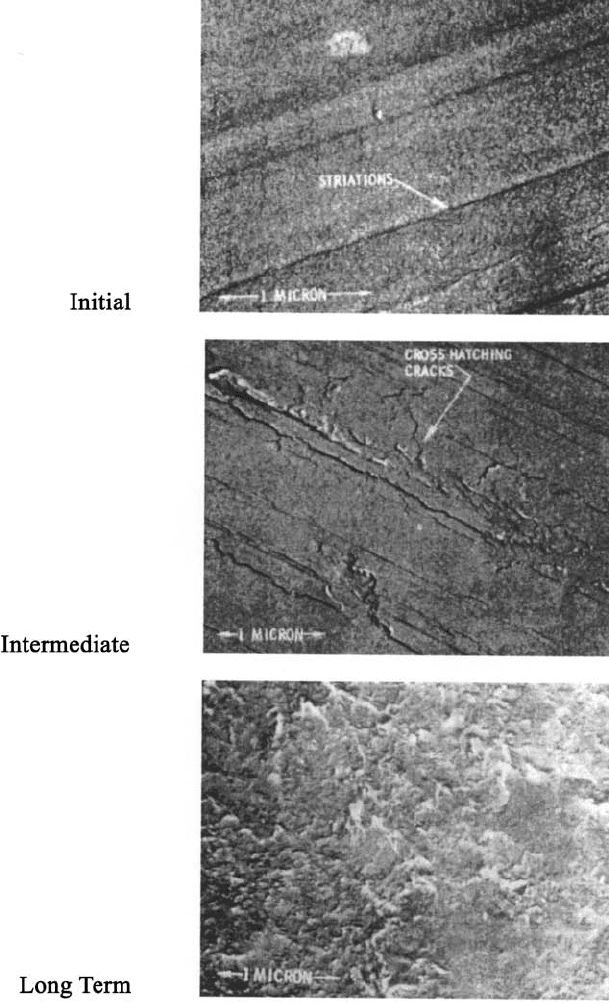
Figure 3.23 Changes in wear scar appearance as a function of the amount of sliding. Data are for
lubricated sliding between a steel sphere and a single crystal copper flat. (From Ref. 20.)
Copyright 2004 by Marcel Dekker, Inc. All Rights Reserved.
shakedown. This is illustrated in Fig. 3.28. Again fracture ultimately resul ts from crack
formation and propagation, that is, fatigue.
The common concept associated with the typical forms of repeated-cycle deforma-
tion wear is fatigue or, more appropriately, fatigue wear. The basic concept of fatigue wear
is that with repeated sliding, rolling, or impacting, material in the vicinity of the surface
experiences cyclic stress. As a result of this, stress cycling, plastic strain accumulates
and cracks are ultimately formed. With further cycling, the cracks propagate, eventual ly
intersecting with the surface and themselves. These intersections then produce free parti-
cles, which are easily removed from the surface by a subsequent motion. This worn surface
also experiences stress cycling and the process continues, resul ting in progressive loss of
material from the surface. This concep t is illustrated in Fig. 3.29.
This type of wear mechanism is most evident in rolling and impact wear situations,
where it is generally recognized as the principal mechanism (71–75). Figs. 3.24 and 3.30
show examples of fatigue wear under such conditions. Fatigue wear is also possible with
sliding (21,23,25,76–78). Examples are shown in Figs. 3.25, 3.27, 3.31 and 3.32. In the case
of rolling and to a lesser degree with impact, the topological features of the wear scar are
often quite suggest ive of crack initiation and propagation. Under sliding conditions, the
topological features are generally not as suggestive. There are several reasons for this.
Features associated with adhesive and abrasive mechanisms frequen tly confound the
appearance in sliding situations. Smearing on the surface also tends to hide surface cracks
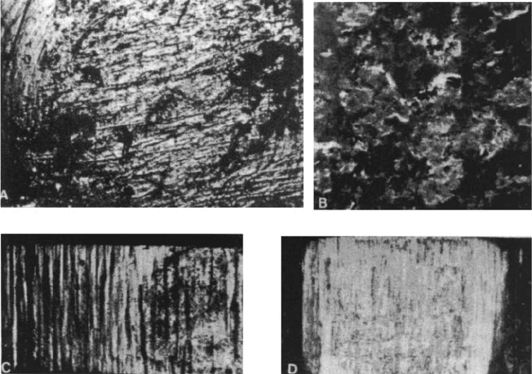
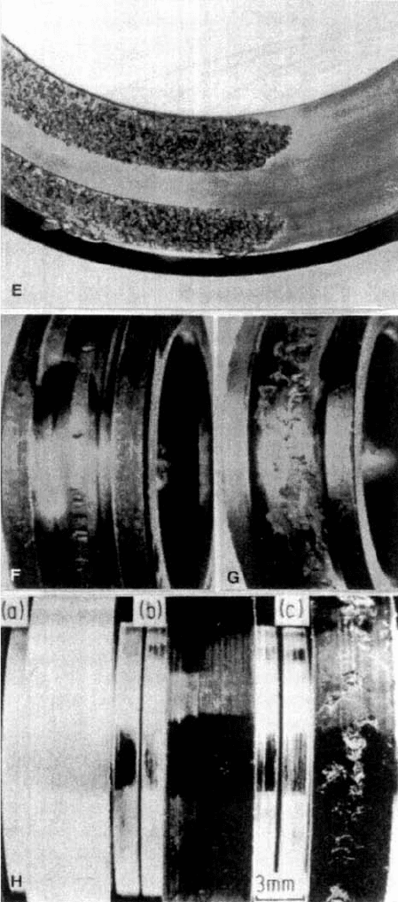
Figure 3.24 Examples of surface fatigue wear in metals under conditions of normal impact (A–D)
and rolling (E–H). (‘‘A’’–‘‘D’’ from Ref. 75; ‘‘E’’–‘‘G’’ from Ref. 73; ‘‘H’’ from Ref. 71; (‘‘A’’–‘‘D’’
reprinted with permission from Elsevier Science Publishers; ‘‘E’’, original source The Torrington
Co., and ‘‘F’’ and ‘‘G’’ reprinted with permission from Texaco’s magazine Lubrication: ‘‘H’’ rep-
rinted with permission from ASME.)
Copyright 2004 by Marcel Dekker, Inc. All Rights Reserved.
with sliding. In addition, the crack network under rolling and impact tends to be more
macroscopic or coarser than those often encountered under sliding conditions and fre-
quently result in larger particles or pits being formed. This tends to make fatigue features
Figure 3.24 (continued )
Copyright 2004 by Marcel Dekker, Inc. All Rights Reserved.
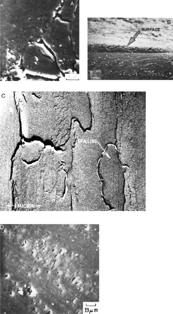
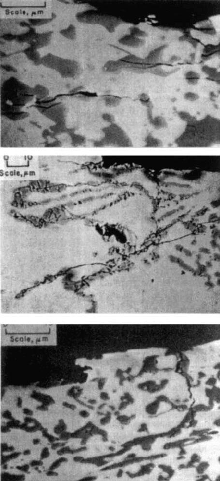
Figure 3.25 Examples of surface fatigue wear in metals (‘‘A’’, ‘‘B’’, and ‘‘C’’) and plastics (‘‘D’’) as
a result of sliding. (‘‘A’’ from Ref. 9; ‘‘B’’ from Ref. 24; ‘‘C’’ from Ref. 20; ‘‘D’’ from Ref. 21; A’’ and
‘‘D’’ reprinted with permission from ASME; ‘‘B’’ and ‘‘C’’ reprinted with permission from Elsevier
Sequoia S.A.)
Copyright 2004 by Marcel Dekker, Inc. All Rights Reserved.
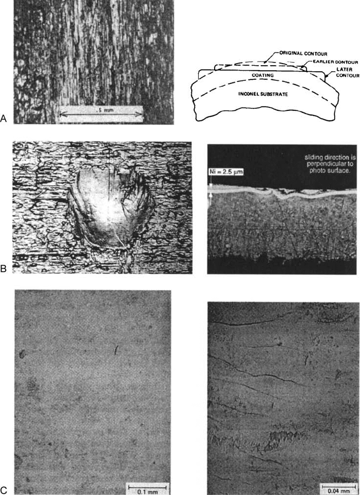
Figure 3.26 ‘‘A’’ shows the wear of a lead coated c-ring as a result of small amplitude oscillations,
which results from creep. An example of wear resulting from progressive subsurface flow is shown in
‘‘B’’. These micrographs show the wear of an electrical tab on a circuit board as a result of small
amplitude oscillations. The left-hand micrograph shows the deformation of the substrate. ‘‘C’’ shows
the worn surface of an elastomer slab subjected to repeated impact. Two modes are shown. In the
left-hand micrograph, there is no material loss but the material is permanently deformed, which
results from a compression set type of behavior. In the right-hand, there is material loss resulting
from fatigue. (‘‘A’’ is from Ref. 178, ‘‘B’’ is from Ref. 179, ‘‘C’’ is from Ref. 180.)
Copyright 2004 by Marcel Dekker, Inc. All Rights Reserved.
more easily detected in the case of rolling and impact. Because of these aspects, often the
only way to determine the existence of cracks under sliding conditions is by means of
microscopic examination of cross-sections through the worn surface, such as those shown
in Figs. 3.25b, 3.27, 3.30, 3.31b and 3.32d. Magnifications of several hundred times or
more are generally required for this.
While fatigue wear and fatigue, that is structural fatigue, share a common basic con-
cept, namely the formation and propagation of cracks, they have different characteristics.
While both have an incubation period, the periods are not the same. With fatigue, the
incubation period is the period of crack formation. With fatigue wear the incubation per-
iod extends beyond this. For fatigue wear, the incubation period involv es the propagation
of the cracks to the surface and generally the formation of loose particles. Some topolo-
gical changes might be evident during this initial period of fatigue wear, including some
evidence of plastic deformati on. Howeve r, there is no loss of material from the surface
or formation of free particles. There are also further distinctions between fatigue wear
and fatigue. With fatigue, the process simply involves the formation and propagation
of cracks. With fatigue wear the process is a continuous cycle of crack formation,
Figure 3.27 Crack structure in delamination wear. (From Ref. 24, reprinted with permission from
Elsevier Sequoia S.A.)
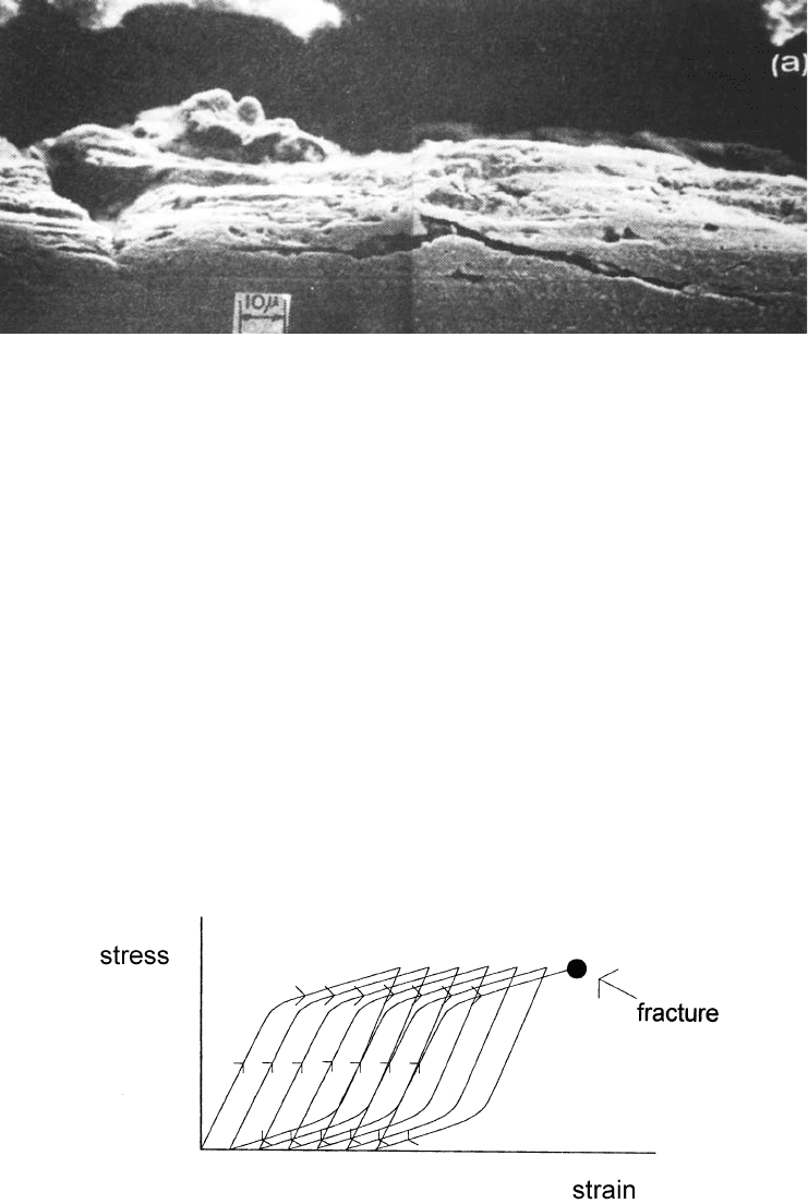
Figure 3.28 Conceptual illustration of the ratcheting wear mechanism. The diagram shows the
accumulation of strain as a result of repeated stress cycling, which leads to fracture.
Copyright 2004 by Marcel Dekker, Inc. All Rights Reserved.
propagation, and removal. For fatigue, most materials exhibit an endurance limit, that is,
a stress level below which fractu re will not occur. In the case of fatigue wear, there does
not appear to be such a limit at least in terms of macroscopic loads and stresses. For prac-
tical load conditions, no matter how small the load or stress, sufficient rolling, sliding or
impact results in the generation of fatigue wear. A further difference is that with fatigue a
distinction is often made between low cycle fatigue and high cycle fatigue. A similar dis-
tinction is not made with fatigue wear.
For rolling situations, there is a generally accepted empirical relationship between
load and the number of revolution defining the incubation period (77,79–81). The general
form of the relationship for both point and line contact situations is
N
1
P
n
1
¼ N
2
P
n
2
ð3:29Þ
where N
1
is the number of revolutions req uired for a load of P
1
and N
2
the number of
revolutions required for a load of P
2
. For point contact situations, such as in a ball
bearing, n is 3; for line contact, such as in a roller bearing, n is 10=3. Frequently this
relationship is referred to as Palmgren’s equation (81,82). A more fundamental form of
this equation relates stress to number of revolutions. Since according to elastic contact
theory (83) , the maximum stress in a point contact situation, S
m
, is proportional to P
1=3
,
the stress form of Eq. (3.29) becomes
N
1
S
9
m
1
¼ N
2
¼ S
9
m
2
ð3:30Þ
Similar relationships exist for sliding and impact, as described later in this section (21,84).
The progression of wear scar morphology for fatigue wear under sliding conditions
was studied in Cu. (21) The sliding system consisted of a hardened steel sphere sliding
back and forth across the flat surface of Cu single crystals. Boundary lubrication was used
and stress levels were maintained well under the yield point of the Cu. Three stages were
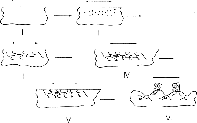
Figure 3.29 General model for surface fatigue wear. Stage I, stress cycling of surface; Stage II,
nucleation of cracks in near-surface regions; Stage III, crack growth; Stage IV, crack coalescence;
Stage V, crack intersection with surface; Stage VI, formation of loose particles.
Copyright 2004 by Marcel Dekker, Inc. All Rights Reserved.
identified and are shown in Fig. 3.32. In the first stage, grooves and striations in the direc-
tion of sliding were the predominate feature. There was no material loss and the topo-
graphy would suggest single-cycle deformation. During this stage, as sliding increased, the
Figure 3.30 Examples of cracks formed under impact conditions. (From Ref. 181, reprinted with
permission from ASME.)
Copyright 2004 by Marcel Dekker, Inc. All Rights Reserved.
density or number of these grooves increased. In the second stage, damage features per-
pendicular to the sliding direction appeared. Again, there was no loss of material. This fea-
ture, termed crosshatching, implied something other than a single-cycle deformation mode
was occurring. As sliding continues in this stage, the crosshatching became more pro-
nounced until ultimately spalling and flaking occurred. This is the start of the third and
final stage. In this stage, material loss occurs and, with continued sliding, a wear groove
of increasing depth is formed. The start of the third stage was considered to be the end
of the incubation period.
The striations of the first stage are the result of local stress systems associated with
individual asperity contact. However, the crosshatching features occur over many stria-
tions and are therefore probably associated with the overall stress syst em associated with
the macro-geometry of the contact. This feature is also considered to be associated with
the initiation and growth of subsurface cracks. Micrographs of cross-sections through
the wear scar confirmed the existence of sub-surface cracks in this situation, as shown
in Fig. 3.32d.
In the same study, it was found that the number of cycles required to initiate the
third stage could be correlated to the maximum shear stress associated with the macro-
geometry. In fact, a relationship identical to Eq. (3.30) was found. This c orrelation is
shown in Fig. 3.33. It is significant to note that the same type of correlation wi th stress
is found in impac t wear situations when the macro-stresses are within the elastic limit
of the materials (84). As stated earlier, a similar correlation is found with rolling.
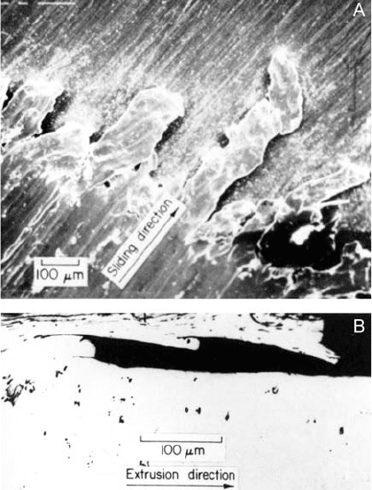
Figure 3.31 Crack structure in extrusion wear. In ‘‘A’’, the surface morphology of the wear scar is
shown. In ‘‘B’’, a view of the cross-section through the wear scar. (From Ref. 87, reprinted with
permission from ASME.)
Copyright 2004 by Marcel Dekker, Inc. All Rights Reserved.