Bayer R.G. Mechanical Wear Fundamentals and Testing, Revised and Expanded
Подождите немного. Документ загружается.

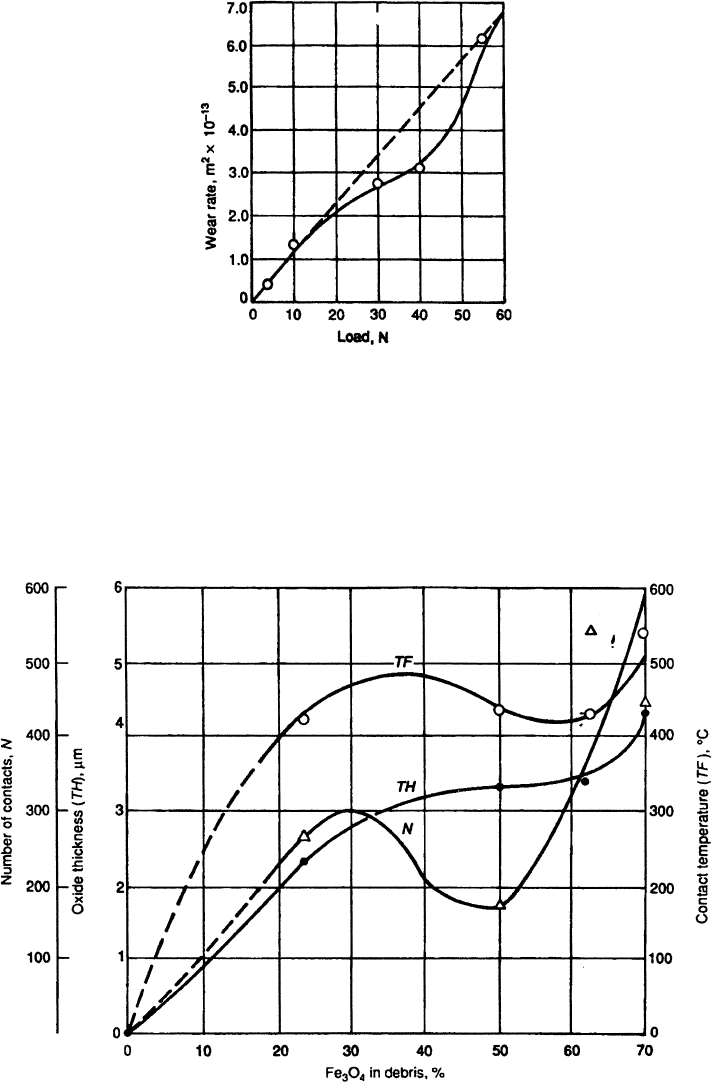
the wear study using EN31, discussed previously, oxidative wear did not occur for loads
under 4 N. It is also possible that under some loading conditions oxidative wear processes
may not be significant, even though oxidation occurs, because the dominant wear process
involves failure underneath the oxide layer.
Figure 3.48 Example of the variation in wear rate with load for unlubricated sliding between
self-mated steel. (From Ref. 98 reprinted with permission from ASM International.)
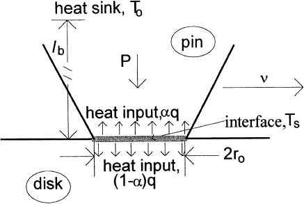
Figure 3.49 Variation of oxide thickness, TH, number of junctions, N, and junction temperature,
TF, as a function of the percentage of Fe
3
O
4
in the wear debris. Data are for unlubricated sliding
between self-mated steel. (From Ref. 98, reprinted with permission from ASM International.)
Copyright 2004 by Marcel Dekker, Inc. All Rights Reserved.
The formation of oxides on a metal surface tends to reduce the wear. For example, in
unlubricated sliding experiments with Cu, the author has observed an order of magni tude
or more reduction in wear rate with the development of a Cu oxide on the surface.
However, this is not always the case. A two order of magni tude increase in the wear rate
of some steels has been observed in air over that obtained in vacuum (107). It should be
recognized that the term oxidation is used to imply any chemical reaction altering the com-
position of the surface. It is not limited to effects from exposure to oxygen, though this is a
very common one in many engineer ing applications. Alternate terms for oxidative wear
are chemical wear and corrosive wear .
3.6. THERMAL WEAR PROCESSES
Thermal wear processes are those processes in which the primary cause of the wear is
directly related to frictional and hysteretic heating as a result of relative motion. For most
materials, thermal wear processes are generally limited to situations involving frictional
heating as a result of relative sliding. However, with viscoe lastic materials, thermal wear
can occur as a result of hysteretic heating that is associated with any type of motion. Melt-
ing, thermal cracking, and thermal mounding or thermoelastic instability (TEI) are the
most common forms of these processes but not the only ones. For example, evaporation
and sublimation are other forms of thermal wear processes. All of these processes are
related to the surface and near-surface temperature distributions that arise as a result of
heating. These are usually characterized in terms of two temperatures. One temperature
is the nominal temperature of the surface. The other is the maximum temperature at
the asperity tips or junctions, which is called the flash temperature. With frictional heating
the flash temperature is greater than the surface temperature. It can be several hundreds of
degrees or more higher than the surface temperature and can reach the order of a few
thousand degrees centigrade under some circumstances. Als o, it is often the more impor-
tant of the two.
Generally, these two temperatures are computed using different models (98,108,109).
The linear heat conduction models used for a pin sliding on a disk shown in Figs. 3.50 and
3.51 illustrate this (109).
Figure 3.50 Model used for the bulk temperature increase of the surface. l
b
is defined as the equiva-
lent linear diffusion distance for bulk heating. It is the effective distance from the interface to a
region that can be considered as a heat sink.
Copyright 2004 by Marcel Dekker, Inc. All Rights Reserved.
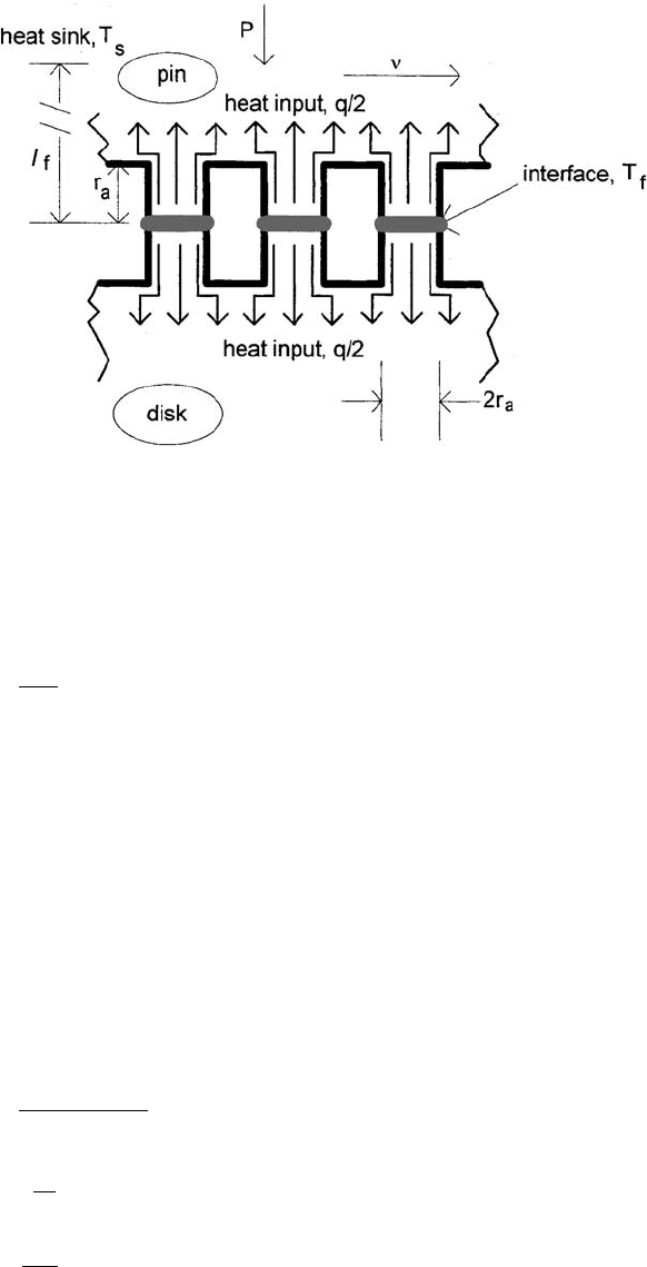
The model for the bulk temperature is based on the apparent area of contact as
shown in Fig. 3.50. The heat generated per unit area per unit time is given by
q ¼
mPn
A
a
ð3:68Þ
where m is the coefficient of friction; P, the load; A
a
, the apparent area of contact; n, is the
sliding velocity. The model assumes that this is shared between the two bodies, a fraction,
a, going into the pin and (1 a) go ing into the disk. The heat flow into the pin and disk is
different and as a result two different models are used to describe the temperature distribu-
tion in these bodies. The pin experiences a continual source of heat and the heat flow is
described by the first law of heat flow. The disk is described by time-dependent equations
for heat flow for the injection of heat. The quantity of heat that is injected is 2(1 a) qr
o
=n.
For self-mated materials, this model results in the following equation for the surface tem-
perature, T
s
(109).
T
s
¼ T
0
þ 2abmT
F
p
PP ð3:69Þ
where
a ¼
2
4 þ bðpF
p
Þ
1=2
ð3:70Þ
T
¼
ap
k
ð3:71Þ
PP ¼
P
A
a
p
ð3:72Þ
Figure 3.51 Model used for determining flash temperature. l
f
is defined as the equivalent linear dif-
fusion distance for flash heating. It is the effective distance from the junction interface to a region
that can be considered as a heat sink.
Copyright 2004 by Marcel Dekker, Inc. All Rights Reserved.

F
p
¼
r
0
n
2a
ð3:73Þ
In these equatio ns, p is the hardness, k is the thermal conductiv ity, and a is the thermal
diffusivity. F
p
is the Peclet Number. Essentially this is the ratio of the time it takes for
the temperature to reach a maximum at a depth of half the width of the contact to the time
it takes for the heat source to move half the contact width.
For a stationary heat source
the Peclet Number is 0. For Peclet Numbers below 0.1, stable temperature distributions
are established in both bodies during the time of contact. As a result the heat flow into
both the pin and the disk can be considered as from a stationary source. In this case,
the heat is uniformly divided between the two bodies, a is 0.5. For Peclet Numbers above
0.1, the thermal distribution in the disk is not stabilized during the contact time and as a
result more heat tends to flow into the disk. For Peclet Numbers above 100, almost all the
heat flows into the disk. For intermediate values, the portion of the heat going into the
disk increases with increasing speed, that is increasing Peclet values.
b in these equations is a dimensionless linearization factor introduced to account for
the fact that the heat flow is three-dimensional, not linearly as assumed by the model. It is
essentially the ratio of the heat diffusion distance into the surface to r
o
. The heat
diffusion distance is nominally the depth below the surface where there is no increase in
temperature. For steel b has been found to be approximately 6 (109). Assuming that
the lateral diffusion of the heat is proportional to thermal diffusivity, its value for other
materials can be approximated by
b ¼
5:5 10
5
a
m
2
s
ð3:74Þ
The model for the flash temperature is based on the real area of contact, as illustrated in
Fig. 3.51. In this case, bot h surfaces are described by time-dependent heat flow equations.
For self-mated materials, the model results in the following equations for the flash tem-
perature, T
f
:
T
f
¼ T
s
þ mT
bF
p
r
a
r
0
ð3:75Þ
T
f
¼ T
s
þ
mT
bF
p
PP
1=2
n
1=2
ð3:76Þ
Equation (3.76) resul ts from the additional assumptions that the asperities are plastically
deformed, that is, that the real area of contact is P=p. In this equation, n is the number of
junctions and can be estimated by the following (109):
n ¼
r
0
r
a
2
PPð1
PPÞþ1 ð3:77Þ
It has been found that changes in the real area of contact primarily result from changes in
the number of junctions formed and not from changes in size of the junctions (37,38,110–
114). Studies have shown that the typical radius of junctions is of the order of 10
5
–10
6
m
The time it takes for the temperature to reach a maximum at a depth h is (h
2
=a).
Copyright 2004 by Marcel Dekker, Inc. All Rights Reserved.

but can be much larger and smaller in some circumstances (110–114). For typical situa-
tions, a nominal value of 10
5
m is often used for thermal calculations (109). Generalized
forms of the equations for surface and flash temperatures are given in Table 3.7. In this
table, an equivalent Peclet Number for the stationary heat source surface, F
*
p
, is defined
for consistency. It can be seen that the distribution of heat or the heat partition between
the surfaces is affected by differences in thermal properties between the two surfaces.
Oxide and other layers on surfaces can also have a significant effect on frictional
heating and the apparent conductivity of a surface. This is shown by the following
equation for the effective value of the thermal conductivity of a surface with a thin layer
on it (109):
k
e
¼
k
s
k
l
ð1 z= br
a
Þk
l
þðz=br
a
Þk
s
ð3:78Þ
k
e
is the effective conductivity; k
s
is the con ductivity of the substrate; k
l
is the co nductivity
of the layer; and Z is the thickness of the layer.
Table 3.7 Temperature Equations for Frictional Heating
a
Surface temperature, T
s
Stationary heat source surface (1)
T
s
¼ T
o
þ 2a
s
bmT
1
F
p
1
PP
F
p
1
nr
o
2a
1
Moving heat source surface (2)
T
s
¼ T
o
þ
4ð1 a
s
Þm
p
1=2
T
2
F
p
2
PP
a
s
¼
2
4þp
1=2
T
1
T
2
F
p
1
F
1=2
p
2
Flash temperature, T
f
General
T
f
¼ T
B
þ 2a
f
mT
1
b
2
r
a
r
0
F
p
1
a
f
¼
a
1
k
1
a
1
k
1
þ a
2
k
2
For A
A
¼ P=p
T
f
¼ T
B
þ
2a
f
mT
1
b
1
PP
1=2
F
p
1
n
1=2
n ¼
r
0
r
a
2
Pð1 PÞþ1
T
¼
ap
K
PP ¼
P
A
A
p
F
p
¼
gr
0
2a
b ¼
5:5 10
5
m
2
=s
a
Symbols: P, load; p, hardness of softer surface; a, thermal diffusivity; k,
thermal conductivity; A
A
, apparent area of contact; n, sliding velocity;
m, coefficient of friction; r
0
, radius of apparent contact area; r
a
, radius
of junctions (approximately 10
5
m; n, number of junctions; Fp, Peclet
Number.
a
Based on the Lim=Ashby temperature relationships for self-mated
materials (Ref. 109).
Copyright 2004 by Marcel Dekker, Inc. All Rights Reserved.

Actual temperatures tend to be lower than those predicted by these equati ons, pri-
marily because heat can be dissipated by other mechanisms, such as convection, radiation,
and cooling by lubri cants. Such effects, particularly cooling by lubricants, can result in sig-
nificantly lower temperatures. Temperature increases under lubricated conditions are gen-
erally negligible, except for thermoelastic instability.
Instead of determining the heat partition at the interface, that is, a and (1 a), the
actual tempe rature can be determined by using the values obtained for each surface,
assuming that all the heat goes into that surface. It has been shown that
1
T
¼
1
T
1
þ
1
T
2
ð3:79Þ
T
1
and T
2
are the temperatures obtained for surfaces 1 and 2, assuming all the heat goes
into that surface; T is the actual surface temperature (115).
Most thermal wear processes can be grouped into three general types. One group is
comprised of those processes, which are simply related to the maximum temperature.
Melting, softening, evaporation and sublimation would be examples of this type. The sec-
ond group is comprised of those processes, which are directly related to thermal gradients.
Thermal fatigue and thermal cracking are examples of this type. Those processes, which
result from thermoelastic instability, comprise the last group. All these types of processes
require significant temperature rise. How high a rise is significant depends on the materials
and mechanism. For example, for the first type of mechanism, a rise of less than 100
C can
be significant for some polymers, while a rise in excess of a 1500
C is required for melting
of metals and intermediate temperatures for the other types of mechanisms.
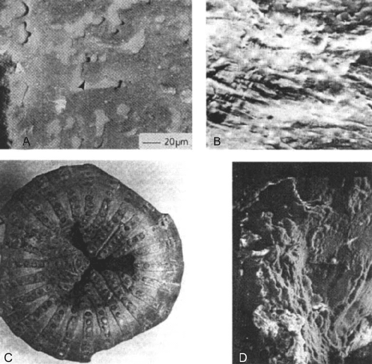
With the first type of thermal mechanisms, wear scars typically exhibit features that
are suggestive of melting, liquid flow, and thermal degradation. Examples of these features
are shown in Fig. 3.52. The following Eq. (3.80), is one proposed for melt wear of a pin
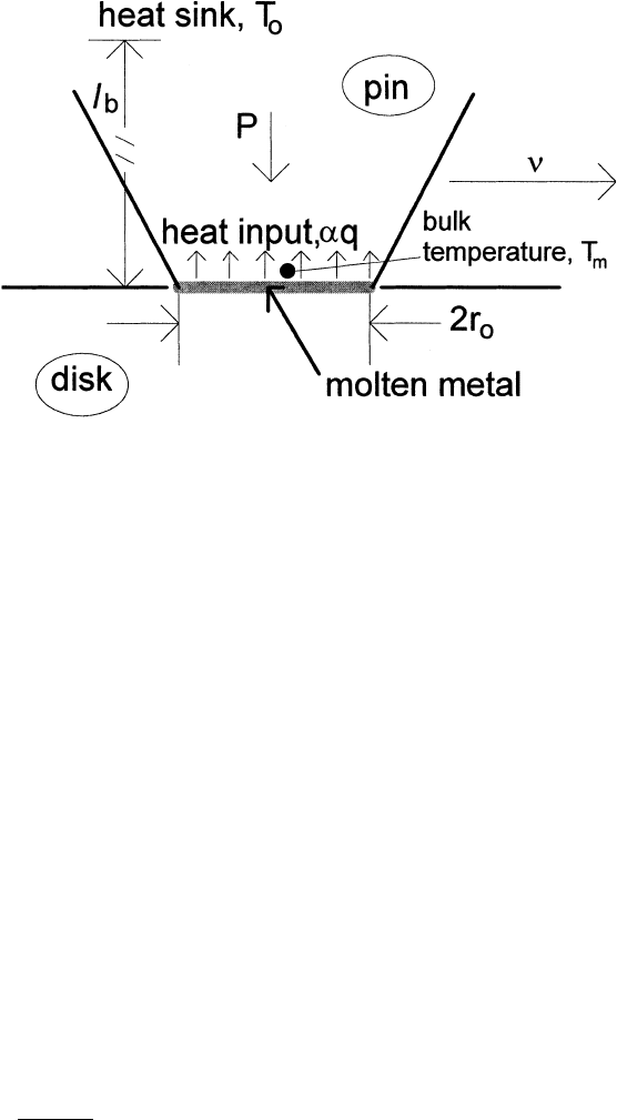
sliding against a disk (109). The model is illustrated in Fig. 3.53. It is based on a lineariza-
tion model for heat flow from a stationary source, similar to the one used to develop Eq.
(3.68). It assumes that a portion of the heat is conducted through the pin, maintaining the
temperature differential, and a portion of the heat is absorbed as latent heat into the
melted layer. The depth rate of wear h
˙
(units of length per unit time) is given by
_
hh ¼ K
k
br
0
L
½ð2aT
bm
PPF
0
p
ÞðT
m
T
0
Þ ð3:80Þ
In this equation, L is the latent heat for melting and T
m
is the melting temperature. F
0
p
has
the same form as the Peclet Number and is the defined as (2r
0
n =a
pin
) (see Table 3.7). K is
the fraction of the molten layer that is lost from the contact per unit time. The correspond-
ing equation for flash temperature melting is Eq. (3.81).
_
hh ¼ K
k
br
a
L
2a
f
T
bm
r
a
r
0
F
0
p
ðT
m
T
0
Þ
ð3:81Þ
Noting that F
0
p
is equal to the Peclet Number for the junction contact, n r
a
=a, times (r
o
=r
a
),
this equation can be rewritten as
_
hh ¼ K
k
br
a
L
½ð2a
f
T
bm F
p
ÞðT
m
T
0
Þ ð3:82Þ
where F
p
is the Peclet Number for the junctions.
Copyright 2004 by Marcel Dekker, Inc. All Rights Reserved.
The second class of thermal wear mechanism is mechanisms resulting from the ther-
mal fluctuation, DT, caused by frictional heating. In some materials fracture can take place
if DT or the thermal strain, e
T
, is large enough. More generally, repeated cycles of DT can
result in the nucleation and propagation of cracks, that is thermal fatigue. As with most
fatigue wear processes, these processes can be described by a power law relationship,
such as,
_
WW / e
n
T
ð3:83Þ
Figure 3.52 Examples of wear scars from situations in which melting has occurred. ‘‘A’’ shows the
worn surface of an unfilled polymer, where melting has taken place as a result of sliding. Regions of
melting are the large patches, such as the one indicated by the arrow. ‘‘B’’ also shows a polymer wear
scar where the melting resulted from sliding. ‘‘C’’ shows a diamond drag bit on which the diamonds
have been burned and flattened in an abrasive wear situation. ‘‘D’’ shows the worn surface of a poly-
mer, where melting and charring has occurred as a result of repeated impacts. (‘‘A’’ is from Ref. 183,
‘‘B’’ is from Ref. 184, ‘‘C’’ is from Ref. 185, and ‘‘D’’ is from Ref. 186, ‘‘B’’, and ‘‘C’’ reprinted with
permission from ASME.)
Copyright 2004 by Marcel Dekker, Inc. All Rights Reserved.
or
_
WW / s
n
T
ð3:84Þ
s
T
is the corresponding thermal stress and W
˙
is wear rate. The exponent is generally 1
or greater and can be large, for example, the order of 10. There is a wide range in the
appearance of wear scars produced by this type of mechanism. Figures 3.54 and 3.55 show
examples of wear scars resulting from thermal fracture and fatigue.
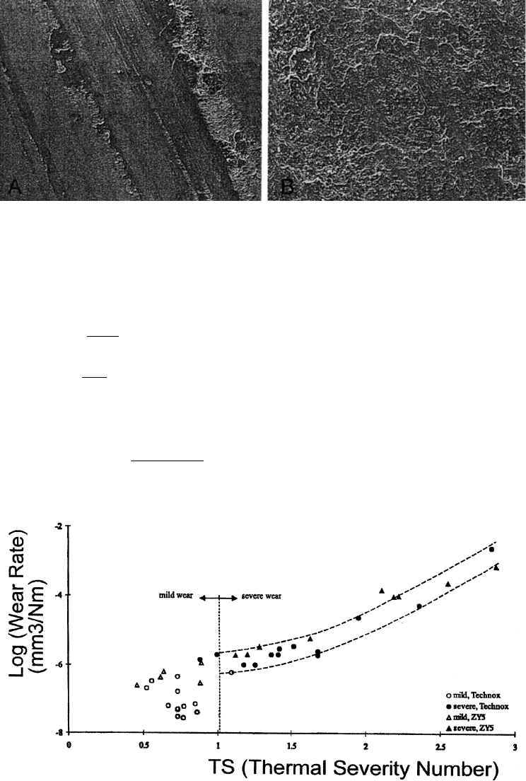
A model has been proposed for the type of thermal wear of ceramics illustrated in
Fig. 3.55. (116) This model assumes that there are micro-cracks in the ceramic and that
the severe wear shown in Fig. 3.55B results from the growth of these cracks. With this
model, it is shown that magnitude of the wear rate in this region can be correla ted with
a thermal severity factor, which is the ratio of the temperature fluctuation, DT , to the ther-
mal shock resistance of the material, DT
s
. This is shown in Fig. 3.56. Analysis of these data
results in the following approximate relationship between this factor, TS, and wear rate:
_
WW / TS
8
ð3:85Þ
The limited data in the mild region suggest a similar relationship with a much lower
exponent.
In the model, the following equation for TS, where k
e
is the effective conductivity of
the contact, is developed:
TS ¼
mPn
DT
S
k
e
r
0
ð3:86Þ
In the model, it is assumed that for crack growth, the following condition, based on linear
elastic fracture theory, must be satisfied:
1:12s
T
ffiffiffiffiffiffi
pd
2
p
K
LC
ð3:87Þ
d is the initial size of the crack and K
LC
is the fracture toughness of the material. It also
Figure 3.53 Model used for surface melting. l
b
is defined as the equivalent linear diffusion distance
for bulk heating. It is the effective distance from the interface to a region that can be considered as
a heat sink.
Copyright 2004 by Marcel Dekker, Inc. All Rights Reserved.
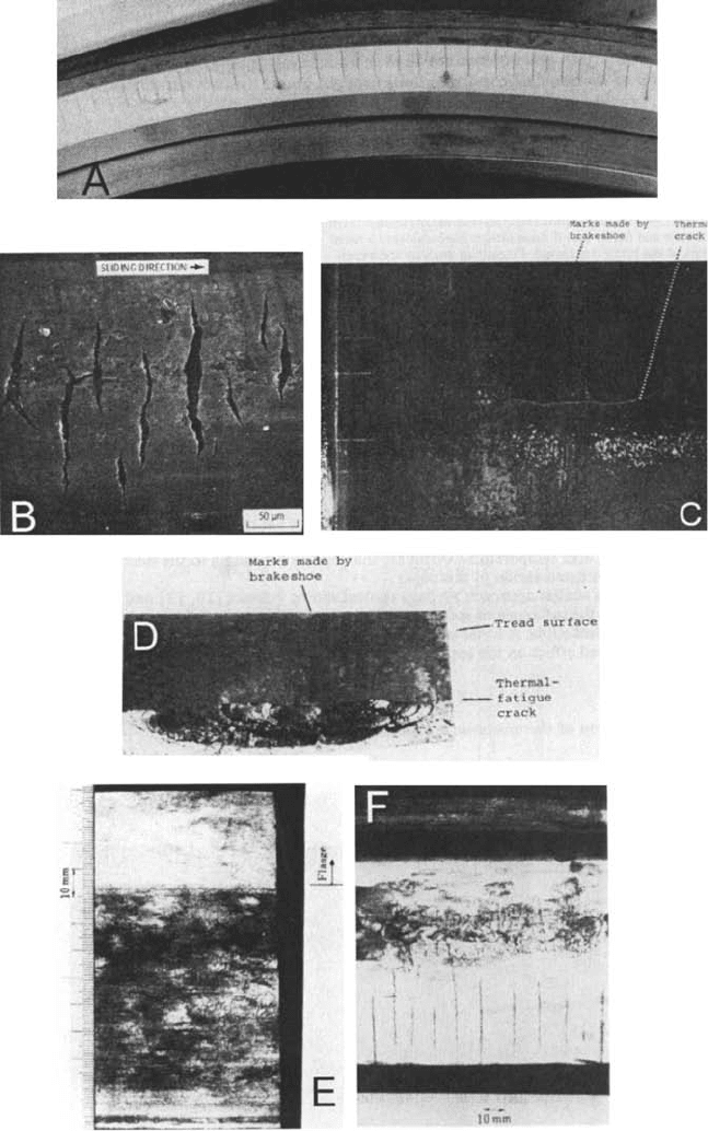
Figure 3.54 Examples of thermal cracks and thermal fatigue as a result of sliding. ‘‘A’’ and ‘‘B’’ are
on the worn surfaces of metal seals. ‘‘C’’, ‘‘D’’, ‘‘E’’, and ‘‘F’’ are wear scars on metal train wheels.
(‘‘A’’ is from Ref. 117, ‘‘B’’ is from Ref. 187, ‘‘C’’–‘‘F’’ from Ref. 188, reprinted with permission
from Elsevier Sequoia S.A.)
Copyright 2004 by Marcel Dekker, Inc. All Rights Reserved.
assumes the following relationships for s
T
and DT:
s
T
¼
El
1 Z
DT ð3:88Þ
DT ¼
mPn
r
0
k
e
ð3:89Þ
E is Young’s Modulus; l, the coefficient of thermal expansion; Z, is Poisson’s ratio. It is
also assumed that K
LC
and DT
s
are related by the following equation:
DT
s
¼ DT
s0
þ
cð1 ZÞK
LC
El
ffiffiffiffiffiffi
pd
2
p
ð3:90Þ
In this equation, DT
s0
is an offset value and c is the proportionality constant.
Figure 3.55 Examples of thermal wear scars on ceramics. The micrographs show the appearance of
a wear scar on the zirconia specimen after sliding against an unlubricated alumina ball at two dif-
ferent speeds. ‘‘A’’ is 0.15 m=s and ‘‘B’’ is 0.40 m=s. (From Ref. 116, reprinted with permission from
Elsevier Sequoia S.A.)
Figure 3.56 Wear rate as a function of the thermal severity number, TS. (From Ref. 116, reprinted
with permission from Elsevier Sequoia S.A.)
Copyright 2004 by Marcel Dekker, Inc. All Rights Reserved.