Bhushan B. Handbook of Micro/Nano Tribology, Second Edition
Подождите немного. Документ загружается.

© 1999 by CRC Press LLC
(10.28)
where
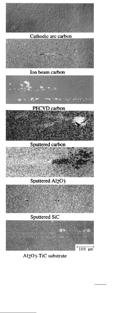
FIGURE 10.56 Optical images of worn DLC, ion
beam–sputtered Al
2
O
3
, and RF-sputtered SiC films
deposited on Al
2
O
3
–TiC substrates and the bare sub-
strate, slid against a single-crystal sapphire ball
(diameter = 3 mm) for 2 h at a 10 mN normal load,
3.5 mm stroke length, 0.1 Hz frequency, 0.7 mm s
–1
average linear speed, and under ambient temperature
of 22 ± 1°C and humidity of 45 ± 5% RH. (From
Gupta, B.K. and Bhushan, B., 1995, Wear 190,
110–122. With permission.)
h
Wa
D
gk=
π
()
2
16
© 1999 by CRC Press LLC
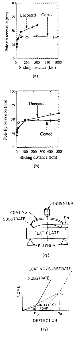
FIGURE 10.57 Pole tip recession as a function of sliding distance as measured
with an atomic force microscope for (a) uncoated and ion beam carbon-coated,
and (b) uncoated and cathodic arc carbon-coated Al
2
O
3
–TiC heads run against
MP tapes.
FIGURE 10.58 (a) Schematic diagram of the deflection measurement
of a bent beam using a nanoindenter and (b) load–deflection curve for
a warped composite-beam substrate.
© 1999 by CRC Press LLC
where a is the radius of the membrane, t is its thickness, and the function g(k) depends on the membrane
and its geometry. If the geometry and elastic constants of the membrane are known, the tension can be
accurately evaluated. This technique can only be used to study tensile residual stresses since compressive
stresses buckle the membrane when the substrate is removed.
10.6.4 Microwear Measurements Using Modified Nanoindentation
Wu and Lee (1994) modified the nanoindenter/nanoscratch technique for microwear studies. A piezo-
electric pusher with a servo control was employed to implement a reciprocating horizontal motion at
the indenter tip for implementing a microwear test. Through a lock-in detection scheme, they measured
friction force.
10.7 Other Applications of Nanoindentation Techniques
Nanoindentation techniques have been used for measurement of time-dependent viscoelastic/plastic
properties (creep/relaxation), nanofracture toughness, and nanofatigue.
10.7.1 Time-Dependent Viscoelastic/Plastic Properties
Most materials including ceramics and even diamond are found to creep at temperatures well below half
their melting points, even at room temperature. Indentation creep and indentation load relaxation (ILR)
tests are used for measurement of the time-dependent flow of materials. These offer an advantage of
being able to probe the deformation properties of a thin film as a function of indentation depth and
location.
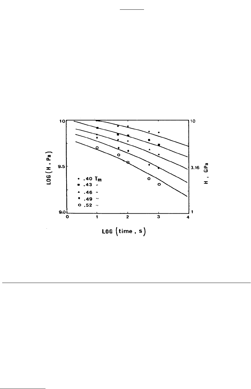
FIGURE 10.59 Indentation creep data for Si at different temperatures. (From Li, W.B. et al., 1991, Acta Metall.
Mater. 39, 3099–3110. With permission.)
D
Et
=
−
()
3
2
12 1 ν
© 1999 by CRC Press LLC
In the indentation creep test, the hardness indenter maintains its load over a period of time under
well-controlled conditions, and changes in indentation size are monitored (Westbrook, 1957; Mulhearn
and Tabor, 1960/61; Atkins et al., 1966; Walker, 1973; Hooper and Brookes, 1984; Li et al., 1991). The
analysis of creep is more complex than that of creep data obtained using a conventional technique because
of the shape of the tip, indentation stress acting on the sample decreases with time as the contact area
increases. Chu and Li (1977, 1979, 1980) developed an impression creep test on a macroscale which used
a circular tip with a flat end. Log (hardness) decreases (linearly for most metals) with log (time at load).
Nanoindentors are also used for indentation creep studies (Li et al., 1991; Lucas and Oliver, 1992; Raman
and Berriche, 1990, 1992). Figure 10.59 shows the plot of log (indentation hardness) as a function of log
(time) for silicon at different temperatures. Indentation creep is influenced by a large number of variables
such as the plastic deformation properties of the material, diffusion constants, normal load of indenter,
duration of the indentation, and the test temperature. Li et al. (1991) reported that for temperatures
between 27°C and melting, the mechanism of dislocation glide plasticity dominates the indentation creep
process.
In a typical ILR test, the indenter is first pushed into the sample at a fixed displacement rate until a
predetermined load or displacement is achieved and the position of the indenter is then fixed. The
material below the indenter is elastically supported and will continue to deform in a nonelastic manner,
thereby tending to push the indenter farther into the sample. Load relaxation is achieved by conversion
of elastic strain in the sample into inelastic strain in the sample. During the test, the load and position
of the indenter and the specimen are continuously monitored. Normally the indenter motion is held
constant and the changes in the load are monitored as a function of time. It is possible to obtain the
plastic indentation rate from the indentation load and total depth information during the relaxation run
(Hart and Solomon, 1973; Chu and Li, 1980; Nastasi et al., 1993). The resulting load relaxation data are
reported in the form of log (indentation pressure) as a function of log (plastic indentation strain rate)
(Hannula et al., 1985; LaFontaine et al., 1990a,b; Wu, 1991).
The indentation pressure is calculated by dividing the load by the projected area of the indenter. Once
the plastic indentation depth is known as a function of time, the projected area is determined experi-
mentally as described earlier. The plastic indentation strain rate — [(1/h)(dh/dt), where h is the current
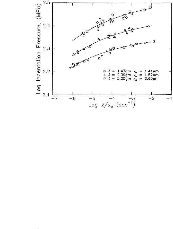
FIGURE 10.60 Indentation load relaxation data of a (111) single-crystal aluminum sample at 25°C; l is the load,
x
o
is the plastic indentation depth at the beginning of the relaxation, and
·
x is the plastic indentation rate. (From
LaFontaine, W.R. et al., 1990, J. Mater. Res. 5, 2100–2106. With permission.)
© 1999 by CRC Press LLC
indentation depth] — is calculated in the manner similar to that for bulk relaxation data. First, the plastic
indentation depth is calculated which is equal to the total depth minus its elastic depth based on load
vs. time data. The plastic indentation depth vs. time data is divided into segments. Over each segment,
the plastic indentation depth is assumed to vary linearly with time. At the midpoint of each segment the
slope of the plastic indentation depth curve is determined to obtain the plastic indentation rate. The
average plastic indentation depth is used along with the corresponding average load over the same time
interval to determine the indentation pressure (LaFontaine et al., 1990b). Figure 10.60 shows typical log
(indentation pressure) vs. log (normalized plastic indentation rate normalized with the depth at the
beginning of the relaxation experiment) flow curves for a (111) single-crystal aluminum.
Another technique to measure strain rate sensitivity of submicron films was developed by Mayo and
Nix (1988a,b). They developed two procedures. In the first procedure, known as the constant rate of
loading test, individual indentations are performed at a prescribed loading rate that is varied from one
indentation to another by about a factor of 2. The values of the indentation pressure and strain rates
from tests performed at different loading rates were compared at a common indentation depth. In a
second related technique known as the loading rate change test, the loading rate is held constant at a
specified depth, but is suddenly changed to a new value and the subsequent changes in pressure and
strain rate are monitored.
Mayo et al. (1990, 1992) also developed yet another procedure for determining the strain rate sensitivity
of nanophase materials in order to conduct tests at the high loading rates required for very hard materials.
In this procedure, as soon as the indenter contacts the sample surface, the indenter loading rate is
instantaneously increased to a high value and this value is maintained until the indenter reaches a
prescribed displacement. The load is held constant at this point, and the load is monitored as a function
of time. The initial fast descent rate of the indenter produces a substantial amount of creep during a
constant-hold period. A range of descent rates are realized ranging from high values at the beginning of
the hold period to smaller values as the material stops deforming. These correspond to a range of strain
rates, and several stress–strain pairs can be obtained (Raman and Berriche, 1990, 1992).
The strain rate sensitivity of materials is measured in terms of stress exponent, n, which is defined by
the equation,
Plastic indentation rate = A (indentation pressure)
n
(10.29)
where A and n are the constants. The stress exponent is found as a slope of a log–log plot of plastic
indentation rate (or strain rate) and indentation pressure. In the ILR test, the continuous change in the
contact area results in continuous changes in both plastic indentation rate and pressure. Thus, data from
a single indentation test, which may span several orders of magnitude in both strain rate and pressure,
are sufficient to determine the stress exponent. Stress exponent can be used to define the superplasticity
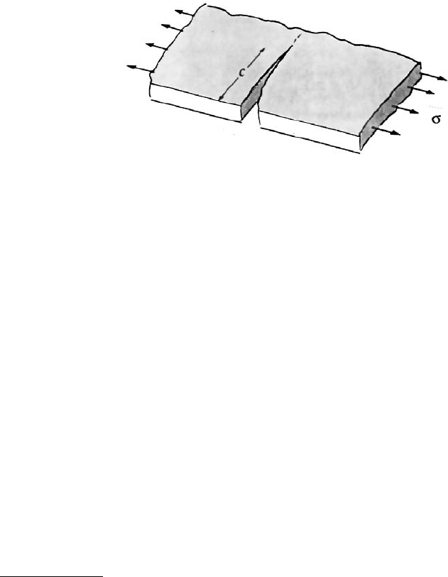
FIGURE 10.61 Schematic of a standard specimen used for measurement of fracture toughness of materials in
tension.
© 1999 by CRC Press LLC
of a material. The variations in stress exponent reflect the changes that may take place when the sub-
structure generated at high strain rate approaches equilibrium condition (Mayo and Nix, 1988a).
10.7.2 Nanofracture Toughness
Fracture toughness, K
Ic
of a material is a measure of its resistance to the propagation of cracks and the
ratio H/K
Ic
is an index of brittleness, where H is the hardness. Resistance to fracture is a strong function
of crack pattern. It is typically measured in a test in which a specimen containing a sharp crack of known
length, c, is subjected to an applied stress s, which is increased during test until the sample fractures
(Lawn, 1993), Figure 10.61. The magnitude of the stresses near the crack tip are determined by the stress
intensity factor K
I
which, in turn, depends on s, c, and the specimen geometry (A)
(10.30)
The term A provides correction for the thickness-to-width ratio of the material. Units of stress-intensity
factor are MPa . With more intense stress or with deeper cracks, the stress intensity becomes sufficient
for the fracture to progress spontaneously. This threshold stress intensity is a property of the material
and is called the critical stress intensity factor, K
Ic
, or the fracture toughness of the material. Ceramics
generally have relatively low fracture toughness, consequently, it is an important property to be considered
for the selection of ceramics for industrial applications.
Indentation fracture toughness is a simple technique for determination of fracture toughness (Palm-
quist, 1957; Lawn and Wilshaw, 1975; Evans and Charles, 1976; Lawn and Evans, 1977; Lawn and Marshall,
1979; Lawn et al., 1980; Antis et al., 1981; Chantikul et al., 1981; Chiang et al., 1981, 1982; Henshall and
Brookes, 1985; Cheng et al., 1990; Cook and Pharr, 1990; Choi and Salem, 1993; de Boer et al., 1993;
Lawn, 1993; Pharr et al., 1993; Bhushan et al., 1996). The indentation cracking method is especially useful
for measurement of fracture toughness of thin films or small volumes. This method is quite different
from conventional methods in that no special specimen geometry is required. Rather, the method relies
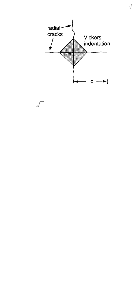
on the fact that when indented with a sharp indenter, most brittle materials form radial cracks and the
lengths of the surface traces of the radial cracks (for definition of crack length, see Figure 10.62) have
been found to correlate reasonably well with fracture toughness. By using simple empirical equations,
fracture toughness can then be determined from simple measurement of crack length.
In microindentation, cracks at relatively high indentation loads of several hundred grams are on the
order of 100 µm in length and can be measured optically. However, to measure toughness of very thin
films or small volumes, much smaller indentations are required. However, a problem exists in extending
the method to nanoindentation regime in that there are well-defined loads, called cracking thresholds,
below which indentation cracking does not occur in most brittle materials (Lankford, 1981). For a Vickers
indenter, cracking thresholds in most ceramics are about 25 g. Pharr et al. (1993), Li et al. (1997), and
Li and Bhushan (1998a) have found that the Berkovich indenter (a three-sided pyramid) with the same
depth-to-area ratio as a Vickers indenter (a four-sided pyramid) has a cracking of the thresholds very
similar to that of the Vickers indenter. They showed that cracking thresholds can be substantially reduced
FIGURE 10.62 Schematic of Vickers
indentation with radial cracks.
KA c
I
=πσ
m
© 1999 by CRC Press LLC
by using sharp indenters, i.e., indenters with smaller included tip angles, such as a three-sided indenter
with the geometry of the corner of a cube. Studies using a three-sided indenter with the geometry of a
corner of a cube have revealed that cracking thresholds can be reduced to loads as small as 0.5 g, for
which indentations and crack lengths in most materials are submicron in dimension.
Based on fracture mechanics analysis, Lawn et al. (1980) developed a mathematical relationship
between fracture toughness and indentation crack length, given as
(10.31)
where W is the applied load and B is an empirical constant depending upon the geometry of the indenter
(also see Lawn, 1993; Pharr et al., 1993). Antis et al. (1981) conducted a study on a number of brittle
materials chosen to span a wide range of toughnesses. They indented with a Vickers indenter at several
loads and measured crack length optically. They found a value of B = 0.016 to give good correlation
between the toughness values measured from the crack length and the ones obtained using more con-
ventional methods. Mehrotra and Quinto (1985) used a Vickers indenter to measure fracture toughness
of the coatings. Pharr et al. (1993) tested several bulk ceramics listed in Table 10.7 using Vickers, Berkovich,
and cube corner indenters. They found that the fracture toughness equation can be applied for the data
TABLE 10.7 Typical Mechanical Properties
of Materials Tested by Pharr et al. (1993)
Material E(GPa) H(GPa) K
Ic
(MPa )
Soda lime glass 70 5.5 0.70
Fused quartz 72 8.9 0.58
(111) Silicon 168 9.3 0.70
(111) Sapphire 403 21.6 2.2
Si
3
N
4
300 16.3 4.0
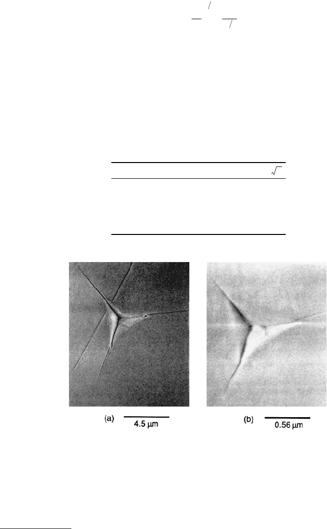
FIGURE 10.63 Indentations in fused quartz made with the cube corner indenter showing radial cracking at inden-
tation loads of (a) 12 g and (b) 0.45 g. (From Pharr, G.M. et al., 1993, in Mechanical Properties and Deformation
Behavior of Materials Having Ultra-Fine Microstructures, M. Nastasi et al., eds., pp. 449–461, Kluwer Academic,
Dordrecht. With permission.)
KB
E
H
W
c
cI
=
12
32
m
© 1999 by CRC Press LLC
obtained with all three indenters provided a different empirical constant was used for a cube corner
indenter. The constant B for the Vickers and Berkovich indenter was found to be about 0.016 and for
cube corner it was about 0.032. Pharr et al. (1993) further reported that predominant cracks formed
with Vickers or Berkovich indenters are cone cracks and with cube corner indenter, predominant cracks
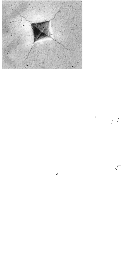
were radial cracks, Figure 10.63. Bhushan et al. (1996) reported that cracks formed in microcrystalline
ceramic material (glass–ceramic) with Vickers indenter are radial cracks, Figure 10.64. Note that cracks
propagate in a zigzag manner. The interlocked crystal morphology is responsible for propagation in a
zigzag manner. By using Equation 10.31, the fracture toughness for this material is calculated and
presented in Table 10.4.
Chantikul et al. (1981) developed a relationship between fracture toughness and the indentation
fracture strength and the applied load given as,
(10.32)
where s
f
is the fracture strength after indentation at a given load and c is an empirical constant (0.59).
Advantage of this analysis is that the measurement of crack length is not required. Mecholsky et al. (1992)
used this analysis to calculate fracture toughness of diamond films on silicon. They indented the films
at various indentation loads of 3 to 9 kg and then fractured in four-point flexure to measure fracture
strength. The data were then used to get fracture toughness. Equation 10.32 was found to hold for the
measurements. They reported a fracture toughness of 6 MPa and 12-µm-thick diamond films on
silicon on the order of 2 MPa .
For fracture toughness measurement of ultra-thin films ranging from 100 nm to few micrometers,
indentation or four-point flexure techniques cannot be used. Because of shallow indentation depths
required in the indentation technique, it is difficult to measure a radial crack length under even SEM.
Li et al. (1997, 1998a) developed a novel technique based on nanoindentation in which through-thickness
cracking in the coating is detected from a discontinuity observed in the load–displacement curve and
energy released during the cracking is obtained from the curve. Based on the energy released, fracture
mechanics analysis is then used to calculate fracture toughness. A cube corner is preferred because the
through-thickness cracking of hard films can be accomplished at lower loads (Li and Bhushan, 1998a).
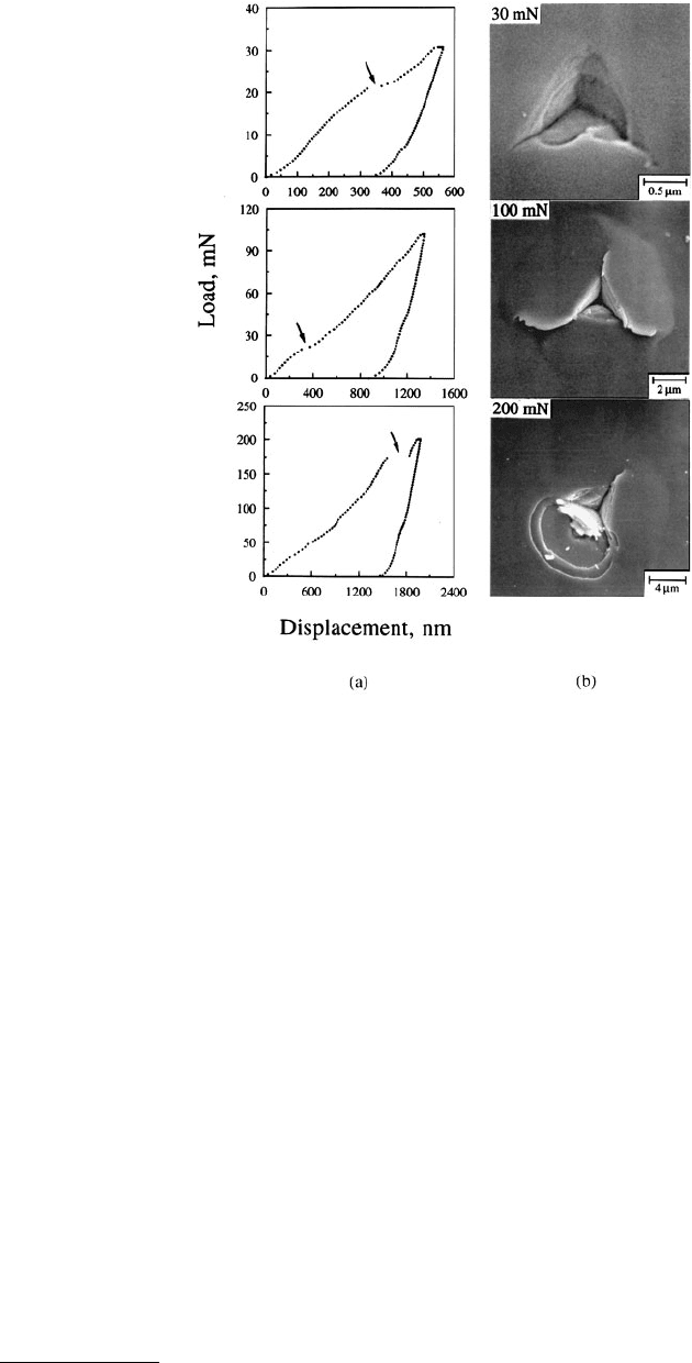
Load–displacement curves of indentations made at 30, 100, and 200 mN peak indentation loads
together with the SEM micrographs of indentations on the cathodic arc carbon coating on silicon are
shown in Figure 10.65. Steps are found in all loading curves as shown by arrows in Figure 10.65a. In the
30-mN SEM micrograph, in addition to several radial cracks, ringlike through-thickness cracking is
observed with small lips of material overhanging the edge of indentation. The step at about 23 mN in
FIGURE 10.64 Optical images of Vickers indentation made
on a glass–ceramic substrate at 500 g load.
Kc
E
H
W
cfI
=
()
18
13
34
σ
m
m
© 1999 by CRC Press LLC
the loading curves of indentations made at 30 and 100 mN peak indentation loads result from the ringlike
through-thickness cracking. The step at 175 mN in the loading curve of indentation made at 200 mN
peak indentation load is caused by spalling.
No steps were observed in the loading curve of indentation made at 20 mN peak indentation load
which suggests that the coating under the indenter was not separated instantaneously from the bulk
coating via the ringlike through-thickness cracking but occurred over a period of time. At 30 mN peak
indentation load, partial ringlike spalling is observed around the indenter and the other parts of the film
bulged upward. This partial ringlike spalling is believed to result in the step in the loading curve. Absence
of long steps in the loading curve for uncoated silicon reported by Li et al. (1997, 1998a) suggest that
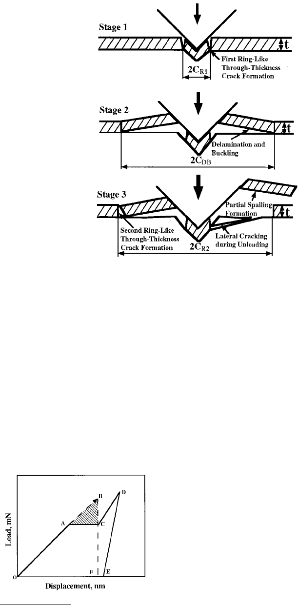
the steps in the loading curve on the coating result from the film cracking. Based on their work, the
fracture process progresses in three stages: (1) first ringlike through-thickness cracks form around the
indenter by high stresses in the contact area, (2) delamination and buckling occur around the contact
area at the film/substrate interface by high lateral pressure, (3) second ringlike through-thickness cracks
and spalling are generated by high bending stresses at the edges of the buckled film, see Figure 10.66. In
the first stage, if the film under the indenter is separated from the bulk film via the first ringlike through-
thickness cracking, a corresponding step will be present in the loading curve. If discontinuous cracks
form and the film under the indenter is not separated from the remaining film, no step appears in the
loading curve because the film still supports the indenter and the indenter cannot suddenly advance into
the material. In the second stage, for the films used in the present study, the advances of the indenter
FIGURE 10.65 (a) Load-displacement curves of indentations made at 30, 100, and 200 mN peak indentation loads
using the cube corner indenter and (b) the SEM micrographs of indentations on the cathodic arc carbon film on
silicon. Arrows indicate steps during loading portion of the load–displacement curve. (From Li, X. et al., 1997, Acta
Mater. 45, 4453–4461. With permission.)
© 1999 by CRC Press LLC
during the radial cracking, delamination, and buckling are not big enough to form steps in the loading
curve because the film around the indenter still supports the indenter, but generate discontinuities which
change the slope of the loading curve with increasing indentation loads. In the third stage, the stress
concentration at the end of the interfacial crack cannot be relaxed by the propagation of the interfacial
crack. With an increase in indentation depth, the height of the bulged film increases. When the height
reaches a critical value, the bending stresses caused by the bulged film around the indenter will result in
the second ringlike through-thickness crack formation and spalling at the edge of the buckled film as
shown in Figure 10.66, which leads to a step in the loading curve. This is a single event and results in
the separation of the part of the film around the indenter from the bulk film via cracking through films.
The step in the loading curve is totally from the film cracking and not from the interfacial cracking or
the substrate cracking.
The area under the load–displacement curve is the work performed by the indenter during elastic–plas-
tic deformation of the film/substrate system. The strain energy release in the first/second ringlike cracking
and spalling can be calculated from the corresponding steps in the loading curve. Figure 10.67 shows a
FIGURE 10.66 Schematic of various stages in nanoindentation fracture for the film/substrate system.
FIGURE 10.67 Schematic of a load–displacement curve, showing
a step during the loading cycle and associated energy release.