Caballero B. (ed.) Encyclopaedia of Food Science, Food Technology and Nutrition. Ten-Volume Set
Подождите немного. Документ загружается.

operates by applying heat to turn the toast darker.
The toaster does not measure the color of the toast. It
does not correct for the fact that the toast is rye,
white, or sourdough, nor if the toast comes in differ-
ent thicknesses.
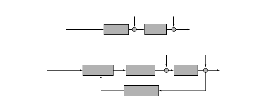
0012 Sensitivity to disturbance and the system’s inability
to correct for disturbances are the main disadvantage
of the open-loop system. Closed-loop control systems
may be used to overcome the drawbacks of open-loop
systems. A closed-loop control system uses an add-
itional measure of the actual output to compare the
actual output with the desired output response. The
measure of the output is called the feedback signal. A
simple closed-loop feedback control system is shown
in Figure 2b.
0013 A feedback control system uses a function of the
prescribed relationship between the output and the
reference input to control the process. At the com-
parison box (Figure 2b), the difference between the
output of the process under control (which arrives via
the feedback path) and the reference input is ampli-
fied and used to control the process so the difference
is continuously reduced. This difference is referred as
the input error (e(t) in Figure 2b).
0014 The comparison box generally consists of an
input transducer that converts the input signal to a
form used by the controller. At the measurement
box, an output transducer (sensor) is used to
measure the output response and also to convert this
response signal to the form used by the controller. For
example, if the controller uses electrical signals to
operate the valve of a temperature control system,
the input position and the output temperature are
converted to electrical signals. Potentiometers are
used to convert input position to voltage. A thermis-
tor, a device that changes its electrical resistance
with temperature, is used to convert output tempera-
ture to voltage.
0015The closed-loop system compensates for disturb-
ances by measuring the output response, feeding the
measurement back through a feedback path, and
comparing that response to the input at the compari-
son box (Figure 2b). If there is any difference between
the two responses (e(t) 6¼0), the system drives the
process to make a correction. If there is no difference
(e(t) ¼0), the system does not drive the process, since
the process response is already the desired response.
Closed-loop systems are also called feedback control
systems.
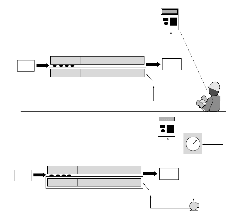
0016To illustrate the concept of feedback control,
Figure 3a shows a simplified manual control of a
baking process. On the outlet side of the oven, there
is an indicator (colorimeter) to provide the operator
with information on the actual value of the biscuit
outlet color (controlled variable). The operator
wants to keep the biscuit final color close to the
desired value. If the operator watches the colori-
meter and finds that the color value is higher (the
biscuit is darker) than the desired response, he/she
will increase the conveyor speed, i.e., the auger
r.p.m. It is considered in this example that the oven
temperature and air flow rate are maintained con-
stant for simplicity. The desired response, of course,
is in the operator’s mind and the operator makes all
of the control decisions. It is quite possible that the
color becomes lighter so the operator will have to
repeat the operation in the opposite direction until
the desired value is reached and kept constant during
the operation.
0017If the operator is replaced by an automatic control-
ler, as shown in Figure 3b, the system becomes an
automatic feedback control system. The actual outlet
biscuit color (the process output), measured by the
colorimeter, is compared to the desired response and
an acting error signal generated. The output color is
converted to the same units of the desired response by
Controller Process
Disturbance Disturbance
Disturbance Disturbance
Output
(a)
(b)
Desired output
response
Comparison
e(t )
m(t )
Controller
Measurement
Process
Output
Desired output
response
fig0002 Figure 2 (a) Open-loop control system; (b) closed-loop control system.
3330 INSTRUMENTATION AND PROCESS CONTROL
a transducer. Based on the acting error value, the
controller calculates the changes that need to be
made in the auger r.p.m. to reduce and then eliminate
that error.
0018 Both manual and automatic controls operate
likewise. In this case, the operator’s eyes correspond
to the acting error device, the brain corresponds to
the automatic controller, and the operator’s muscle
represents the actuator.
0019 Advantages of closed-loop systems as compared
to open-loop systems include greater accuracy
and less sensitivity to noise and disturbances. The
transient response and the steady-state error can
be controlled easily and with great flexibility in
closed-loop systems. On the other hand, closed-loop
systems are more complex and expensive than open-
loop systems.
Computer-Controlled Systems
0020Since the 1970s, process controls have evolved from
pneumatic analog technology through electronic
analog technology to microprocessor-based controls.
0021Nowadays, many systems use a digital computer as
the controller. The use of a computer in the control-
system loop allows for the control and compensation
of many loops by the same computer through time
sharing. In addition, any adjustment of the controller
parameters can be made by changes in software
rather than hardware.
0022One important aspect of computer-controlled
systems is its real-time computing application. It
allows initialization of data acquisition opera-
tions and other tasks as control output calculations,
supervision, scheduling, and so on. Real time means
Raw
biscuit
(a)
(b)
Zone 1
Oven
Oven
Zone 2 Zone 3
Zone 1 Zone 2 Zone 3
Baked
biscuit
Baked
biscuit
Conveyor
Conveyor
Control auger
Auger-r.p.m.
Controller
Desired
response
Colorimeter
Colorimeter
2.00
2.00
Color
Color
Raw
biscuit
M
fig0003 Figure 3 Manual and automatic control of a baking process.
INSTRUMENTATION AND PROCESS CONTROL 3331
that an operation is to be completed within a specified
time constraint.
The Control Problem
0023 The control problem can be stated as follows: deter-
mine the one value of the manipulated variable
(input) that establishes a balance among all the influ-
ences (loads/disturbances) on the controlled variable
(output) and keeps this variable constant at the
desired value.
0024 The steps required to design a control system are:
process description, process and signal modeling,
design method, and control algorithm. Once the con-
trolled, manipulated, and load variables have been
identified, the next step is to describe mathematically
the process and signals (disturbances, reference vari-
ables, initial values). The design methods for linear
control systems can be classified into parameter
optimized control systems and structure optimized
control systems. Once the design method has been
selected, designing principles are applied to determine
the control parameters.
Closed-Control System Analysis and
Design
0025 From the control point of view, a system is composed
of controlled variables, manipulated variables (pro-
cess input), and disturbances. In a control scenario,
the number of manipulated (independent) variables
must be at least as large as the number of controll-
ed (dependent) variables. The controlled variables
should measure product quality directly or strongly
affect it. The manipulated variables should have
a large effect on the controlled variables (large
gain), should rapidly affect the controlled variables
(minimum delay, small time constant), and should
affect the controlled variables directly rather than
indirectly.
0026 Control systems are dynamic systems. That is, the
response of a control system to an input is generally
transient before reaching a steady-state response.
Consider, for example, the baking process
(Figure 3b) where a new biscuit is baked to a darker
color by changing the conveyor speed. When the
desired response (color of the biscuit) is changed to
a higher level (darker), the biscuit entering the oven
will leave the oven with a speed and color accuracy
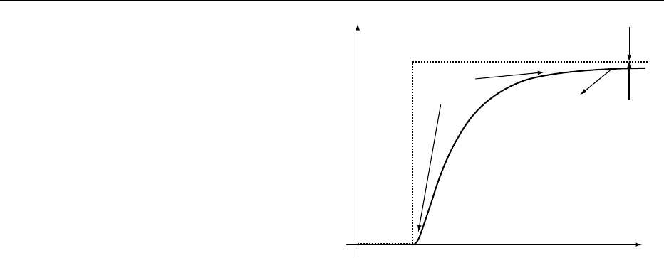
designed for product quality. Figure 4 shows the input
and output for the baking system. The change in the
desired color value is the input and is represented by a
step command. Due to the limited power available
and to keep the products already in the oven from
breaking apart, it is not advised to have the oven
mimicking the suddenness of the input. The input
represents what the output must be after the conveyor
speed has changed; the conveyor follows the change
described by the curved region in Figure 4; this is
termed the oven’s conveyor response. This part of
the response is called the transient response.
0027After the transient response, the process ap-
proaches its steady-state response, i.e., approximates
the desired response. For the baking process example,
this response occurs when the biscuit reaches the
outlet side of the oven. The accuracy of the biscuit’s
final color is a second factor that could make the
output different from the input. This difference is
called steady-state error. Steady-state errors exist
when the control systems are defective.
Transient Response
0028In the baking process presented above, if the transient
response were too slow, the process would be ineffi-
cient (low throughput), whereas an excessively rapid
response would not be sufficient to bake the product
to the desired color. If the conveyor speed oscillated
around the desired response, the product color would
be different from one biscuit to the another, resulting
in poor quality. Therefore, transient response is very
important in the design and analysis of control
systems.
Steady-State Response
0029Another important objective in the analysis and
design of control systems is that the system has a
‘good’ steady-state error performance. The steady-
state response resembles the input and is usually
what remains after the transients have decayed to
zero. In the baking process, this response is the con-
veyor speed modified to a speed that produced the
desired biscuit final color.
Input command
Oven's conveyor response
Color
Time
Steady-state
response
Transient
response
Steady-state
error
fig0004Figure 4 Oven input and output.
3332 INSTRUMENTATION AND PROCESS CONTROL

Stability
0030 System stability under all system operating conditions
is another control system specification. A system is
unstable when its natural response (the way the
system dissipates/acquires energy independently of
the input) is much greater than the forced response
(dependent upon the input) making the system uncon-
trollable. This condition could lead to self-destruction
of the physical device if limit stops are not provided as
part of the design. Therefore, control systems must
be designed to be stable, i.e., their natural response
must decay to zero or oscillate as time approaches to
infinity.
Process Control
0031 The objective of a process control system is to main-
tain a variable in the process at its setpoint (desired
response). A process control system may be either
open-loop or closed-loop, but closed-loop systems
are more common. The process control industry has
developed controllers that are standard and flexible
for closed-loop systems.
0032 Examples of common features shared by many
process controllers include: (1) the values of the set-
point, process, and output variables are shown in
either analog or digital format; (2) the operator is
allowed to adjust the setpoint and switch between
automatic and manual control; (3) when manual con-
trol is selected, the operator is allowed to adjust the
controller output to vary the manipulated variable
in an open-loop control mode; (4) the operator
is allowed to adjust the control model settings to
‘tune the controller’ for optimum response; and (5)
to provide for remote setting of the setpoint by an
external signal. Many additional features are pro-
vided by microcontrollers (microprocessor-based
digital controllers).
0033 A control system (feedback or feedforward) per-
forms essentially three operations: (1) measurement;
(2) manipulation; and (3) signal transmission. Meas-
urement is an integral part of a control system. To
control a variable, its values need to be measured and
converted to suitable signals. Manipulation consists
of use of the control action to manipulate some vari-
able in the process in a way that will tend to reduce
the error. Signal transmission refers to signal commu-
nications between controllers and instruments.
Measuring Transmitter
0034 A measuring transmitter (sensor) senses the value of
a controlled variable and converts it into a usable
signal. Example of sensors include temperature trans-
mitter, flow transmitter, pressure transmitter, etc.
Consider, for example, a temperature transmitter.
The primary element of this sensor could be a thermo-
couple, a resistance element, a thermistor, or a filled
thermal element. The signal transducer receives the
output of the primary element and produces an elec-
tric current signal. In the case of a thermocouple, for
example, it converts temperature into a millivolt
signal, and the thermocouple transducer converts
the millivolt signal into an electric current.
Manipulating Element
0035A controller has two interfaces with the process it
controls: the input interface to the controller, and
the output interface from the controller. The input
side is handled by sensors and signal conditioners.
Various types of manipulating elements handle the
output side.
0036A manipulating element uses the controller output
to regulate the manipulated variable and usually con-
sists of two parts: actuator and final controlling elem-
ent. An actuator translates the controller output into
an action on the final control element, and the final
controlling element changes the value of the manipu-
lated variable. Manipulating elements include valves,
dampers, fans, pumps, heating elements, and electric
motors.
0037The pneumatic control valve is the most common
final control element used to manipulate the flow rate
of a fluid. Figure 5 illustrates a typical pneumatic
control valve. The input to the valve is air pressure
that acts on the diaphragm, compressing the spring,
thus pulling the stem out and finally opening the
valve. The actuator of a pneumatic valve can be
Air
Diaphragm
Actuator
spring
Stem
Plug
Seat
fig0005Figure 5 Pneumatic control valve.
INSTRUMENTATION AND PROCESS CONTROL 3333

described as direct actuator (if the actuator spring is
located below the diaphragm) or reverse actuator
(when the spring is above the diaphragm). The valve
position is the displacement plug from the fully seated
position. The valve action is in the direction in which
the valve plug moves as the air pressure increases.
If the valve closes as the pressure increases, an air-
to-close valve results. If the increased air pressure
opens the valve, it becomes an air-to-open valve.
Signal Transmission
0038 Most signals can be described as analog, digital, or
pulse. Analog signals typically vary smoothly and
continuously over time; digital signals are present at
discrete points in time. In most control applications,
analog signals range continuously over a specified
current or voltage range, such as 4–20 mA DC or
0–5 V DC. Digital signals are essentially on/off (the
pump is on or off), while analog signals represent
continuously variable entities such as temperatures,
pressures, or flow rates. Computer-based control
systems understand only discrete on/off information,
therefore conversion of analog signals to digital
representations is necessary.
0039 Transduction is the process of changing energy
from one form into another. Hence, a transducer is a
device that converts physical energy into an electrical
voltage or current signal for transmission. There are
many different forms of analog electrical transducers.
Examples of transducers include thermocouples and
resistance temperature detectors (RTDs) for measur-
ing temperature via voltage and resistance measure-
ment, respectively. Transmission channels may be
wires or coaxial cables. For noise-resistant transmis-
sion over significant distances, the raw transducer
signal is often converted to a 4–20 mA signal by a
two-wire, loop-powered transmitter.
0040 Industrial networks that transmit data using digital
signals are often an integral part of a process control
solution. Signals from digital instruments and con-
trollers are transmitted in digital format (on–off
pulses) using, for example, a number of parallel
wires. New instrumentation systems use a single
data highway to transmit digital signals to a series
of instruments and controllers. These data highways
are usually coaxial cables linked in serial or daisy-
chain (serial with complete loop). A microcomputer
built in the instrument and controller communicate
periodically over the highway by sending to or re-
questing from information between different devices
installed in the system.
0041 Examples of data highway are wide area network
(WAN) and local area network (LAN). Networks are
communication channels that connect large numbers
of stations to one or more central stations. WANs are
used to connect process systems separated by consid-
erable distance (branch offices in different cities).
LAN is a data highway used to connect local process
units with central operator displays and high-level
computers. LANs are used to connect process systems
located within a radius of about 1.5 km.
0042Nearly all digital network descriptions start with
the open systems interface (OSI) model. The OSI
model is based on several functional levels. The
lower levels are responsible for transmitting messages
between nodes on the same cable and from one cable
to another. The upper levels handle data formatting
and access security. A number of LANs are based on
the OSI model, such as the manufacturing automa-
tion protocol (MAP) and the Ethernet.
0043The MAP is a multilevel communication network
whose objective is to link together all the computers,
controllers, equipment, devices, and offices in an
entire factory. The Ethernet is able to handle error
detection and address the source of destination.
Control Modes
0044The operations performed by a feedback control
system include measurement, decision, and manipu-
lation. A closed-loop control system is shown in
Figure 2b. Measurement and manipulation have
been described above. Decision consists of calculating
the error (desired value minus measured value) and
using the error to form a control action.
0045The control modes convert the error into a control
action (controller output) that will reduce the error.
The most common control modes are the propor-
tional mode (P), the integral mode (I), and the deriva-
tive mode (D).
0046The simplest of the three modes is the proportional
mode. As the name indicates, the proportional mode
produces a control action that is proportional to
error. If the error is small, the control mode will
produce a small action. If the error is large, the con-
trol action will be large. To accomplish the propor-
tional mode, the error is multiplied by a gain
constant, K
p
. In a proportional control, the controller
output is algebraically proportional to the error input
signal to the controller as:
mðtÞ¼K
p
eðtÞð1Þ
where m(t) is the controller output, e(t) is the error
input signal, and K
p
is the controller gain. Eqn (1) is
called the control algorithm.
0047The integral mode produces a control action that
continues to increase its corrective effect as long as
the error persists. The integral mode increases slowly
when the error is small, and corrects more rapidly if
the error is large. Integral control action is based on
3334 INSTRUMENTATION AND PROCESS CONTROL

the principle that the controller output m(t) is propor-
tional to both the size and the duration of the actuat-
ing error signal e(t):
dmðtÞ
dt
¼ K
i
eðtÞð2Þ
or:
mðtÞ¼K
i
ð
t
0
eðtÞdt ð3Þ
where K
i
is an adjustable constant.
0048 The derivative mode produces a control action
that is proportional to the rate at which the error is
changing. If the error is increasing rapidly, the deriva-
tive mode will prevent the error becoming larger by
producing a correction action proportional to how
fast the error is changing. Derivative action (also
called rate control action) is based solely on the rate
of change of the error signal. An ideal derivative
action can be described as:
mðtÞ¼K
d
deðtÞ
dt
ð4Þ
where K
d
is an adjustable constant.
0049 These three control modes can be used alone (with
the exception of the derivative mode) or combined.
The common control mode combinations are: P,
PI, PD, and PID. The proportional plus integral (PI)
control mode is used on processes with large load
changes when the proportional mode alone is not
capable of reducing the offset. The proportional
plus derivative (PD) control mode is used on pro-
cesses with sudden load changes. The proportional
plus integral plus derivative (PID) control mode is
used on processes with sudden, large load changes.
0050Figure 6 shows the typical response behavior of a
controlled process after a step change in the setpoint
occurs. The output variable is shown as a deviation
from the new setpoint change. If no feedback control
is implemented, the process slowly reaches the new
steady state. Proportional control speeds up the pro-
cess and reduces the offset. Adding integral action (PI)
eliminates the offset but causes the loop to oscillate.
The addition of derivative control (PID) made the
response faster and less oscillatory.
Advanced Control
0051The PID controller has been around for more than 50
years and is still today the most widely used industrial
controller. It is simple, easy to understand, and does
not require a precise process model to start up or
maintain. The PID works well if the process system
is simple. However, if the process dynamics change, it
needs to be retuned, and it has trouble controlling
complex systems, i.e., processes that are nonlinear,
time-variant, coupled, and have parameter or struc-
ture uncertainties.
0052Several advanced control strategies exist that can
provide improved process control over PIDs. Some of
these methods include cascade control, robust con-
trol, adaptive control, model predictive control, and
intelligent control. With the advance of computer
control, many of these techniques have been success-
fully applied in the food industry.
0053Cascade control involves two controllers, with the
output controller providing the setpoint of the
Time
No control
PID
PI
Proportional
Offset
Setpoint
Output
fig0006 Figure 6 Step response of a feedback control system. PID, proportional plus derivative; PI, proportional plus integral.
INSTRUMENTATION AND PROCESS CONTROL 3335

secondary controller. The design of controllers or
control algorithms described up to now assumed
that only the control variable determines the process
input. This results in single control loops. By connect-
ing additional measurable variables to the single loop
(i.e., disturbances or auxiliary variables) it is possible
to obtain improved control behavior. These additions
to the single loop lead to interconnected control
systems.
0054 Robust control is a controller design method that
focuses on the reliability (robustness) of the control
algorithm. Robust control methods are suited to pro-
cesses that have large uncertainty ranges and small
stability margins.
0055 Adaptive control is defined as an intelligent feed-
back control system that adjusts its characteristics to
changes in the environment so as to operate in an
optimal manner. In process control applications, the
PID self-tuning scheme is widely implemented in
commercial products.
0056 Model predictive control (MPC) is one of the few
advanced control techniques used successfully in in-
dustrial control applications. The essence of MPC is
based on three key elements: (1) predictive model;
(2) optimization in range of a temporal window;
and (3) feedback correction. These steps are carried
on continuously by computer programs online.
0057 Intelligent methods in control are becoming part of
mainstream control approaches. They integrate con-
cepts and methods from areas such as control, identi-
fication, estimation, communication theory, and
artificial intelligence. Intelligent control paradigms
can endow control systems with functionality that
traditional methods could hardly make available.
They can also improve the analysis, design, oper-
ation, and maintenance characteristics of control
systems. Examples of this type of control strategy
include fuzzy logic and neural network.
0058 Fuzzy logic and neural network aim at mimicking
the operation of the human brain to some extent. A
control law described by fuzzy rules is more under-
standable by a human operator who knows the pro-
cess but who is not an expert control engineer. It
facilitates the integration of heuristic knowledge
about the system and theoretical control laws from
mathematical models, that are always an idealization
of the process.
0059Neural networks go further by aiming at building
models of the way a human being thinks and reaches
conclusions. In general, neural networks are useful
for representing and approximating nonlinear rela-
tionships. They are applicable for multivariable
systems and require less restrictive assumptions on
the process than conventional modeling and control
techniques.
See also: Plant Design: Basic Principles; Designing for
Hygienic Operation
Further Reading
Bateson RN (1999) Introduction to Control System Tech-
nology. Upper Saddle River, NJ: Prentice Hall.
Brescia L and Moreira RG (1997) Modeling and control of
a continuous frying process: II Control development.
Transactions of Chemical Engineering 75(c): 12–20.
Clarke DW, Mohtadi C and Tuffs PS (1987) Generalized
predictive control – part I. The basic algorithm. Auto-
matica 23(2): 137–148.
Clarke DW, Mohtadi C and Tuffs PS (1987) Generalized
predictive control – part II. Extensions and interpret-
ations. Automatica 23(2): 149–160.
Isermann R (1989) Digital Control Systems, vol. II. Sto-
chastic Control, Multivariable Control Adaptive Con-
trol, Applications. New York, NY: Spring-Verlag.
Moreira RG (2001) Automatic Control for Food Processing
Systems. Aspen.
Ogata K (1970) Modern Control Engineering. Englewood
Cliffs, NJ: Prentice-Hall.
Prett DM and Garcia CE (1988) Fundamental Process
Control. Boston, MA: Butterworth-Heinemann.
Schonauer S and Moreira RG (1995) Development of
a fixed-GPC controller for a food extruder based on
product quality attributes. Part I: control development,
implementation and analysis. Transactions of the Insti-
tute of Chemical Engineering Part C 73(C4): 200–210.
Seborg DE, Edgar TF and Mellichamp DA (1989) Process
Dynamics and Control. New York, NY: John Wiley.
Takahashi Y, Rabins MJ and Auslaner DM (1972) Control
and Dynamic System. Menlo Park, CA: Addison-Wesley.
Insulin See Diabetes Mellitus: Etiology; Chemical Pathology; Treatment and Management; Problems in
Treatment; Secondary Complications
Interesterification See Vegetable Oils: Types and Properties; Oil Production and Processing;
Composition and Analysis; Dietary Importance
3336 INSTRUMENTATION AND PROCESS CONTROL

INTERMEDIATE-MOISTURE FOODS
J Sych, Universite
´
Laval, Que
´
bec, Canada
Copyright 2003, Elsevier Science Ltd. All Rights Reserved.
Introduction
0001 Lowering of water activity (a
w
) to a level where
most microorganisms cannot grow is one of the
oldest methods of food preservation and forms
the basis for intermediate-moisture foods (IMF).
This article will review the nature and uses of
IMF by presenting the principles behind formula-
tion, some typical examples on the market, factors
limiting stability, and possible future developments
of IMF.
Principles Behind Formulation of IMF
0002 IMF have a
w
reduced to approximately 0.65 to 0.90
(i.e., moisture content of 15–40%), are plastic
enough to be consumed without rehydration, and
are stable without refrigeration. Other preservative
factors act in association with a
w
to insure the shelf-
life of IMF.
0003 a
w
is the amount of water available for deteriora-
tive processes in a food product and is defined as the
ratio of water vapor pressure of the product (p) to the
saturation pressure of water (p
o
) at the same tempera-
ture: a
w
¼p/p
o
. At low a
w
in food, at or below the
monolayer value, water is strongly bound to specific
sites and unavailable as a solvent for reaction. In the
a
w
range of IMF, the growth of microorganisms is
largely restricted, compared with high-moisture
foods, but certain reactions, such as Maillard and
oxidation, can still proceed, due to the increased solv-
ent and mobilization properties of water above the
monolayer. A reduction of a
w
is achieved by chemical
means (addition of humectants) and/or physical de-
hydration (evaporation, drying, ultrafiltration, etc.).
(See Water Activity: Principles and Measurement;
Effect on Food Stability.)
Processing Technology for IMF
0004 Traditional IMF are processed by the withdrawal of
water, by adsorption or desorption, and/or by the
addition of conventional humectants, such as salt
(sodium chloride) and sugar (sucrose). Although
some traditional IMF, such as dried fruits, are simply
dried to the desired a
w
, most IMF are prepared by a
combination of drying with added humectants.
Bakery products are prepared by adding water and
other ingredients to low-a
w
cereals, followed by
various processing and heating procedures to yield
a
w
in the range of IMF. (See Sucrose: Properties and
Determination.)
0005Novel IMF are often processed by using humec-
tants, such as glycerol, propylene glycol, and sorbitol,
for a
w
adjustment. Combinations of several humec-
tants, each at lower concentrations, are often used
to reduce off-flavor problems. Novel IMF may be
prepared by:
1.
0006Moist infusion (desorption): solid food pieces are
equilibrated in a solution of lower a
w
, often with
heating. Drying may be used to reduce further a
w
(e.g., intermediate-moisture fruits)
2.
0007Dry infusion (adsorption): solid food pieces are
dehydrated and then infused by soaking in a solu-
tion containing humectants (e.g., bite-sized cubes
of meat for space or military rations)
3.
0008Blending: food components are weighed, blended,
cooked, and extruded using various processing
techniques (e.g., fermented meats)
0009IMF processed by adsorption normally have slower
microbial growth and lipid oxidation due to a lower
moisture content than IMF prepared by desorption
with identical a
w
. This is because of sorption hyster-
esis – the phenomenon in foods whereby the moisture
content of a food is lower during equilibration by
adsorption than by desorption. In spite of these
hysteresis effects and the waste of residual infusion
solutions, the desorption method is generally used
more, due to its advantages of lower cost, enzyme
inactivation, and better retention of flavor and struc-
tural integrity. With this method, it is possible to
reduce food weight by 50% by the simultaneous
countercurrent diffusion of water out of the food
and solute into the food.
0010In the production of novel IMF, pasteurization and
blanching are commonly used to reduce initial levels
of microorganisms and to inactivate enzymes. Anti-
mycotics, such as sorbic and benzoic acid and their
salts; methyl and propyl paraben; or calcium propi-
onate, assist in the control of mold and yeast growth.
Other chemical additives may also be incorporated to
slow down physical and chemical deterioration
during storage. (See Pasteurization: Principles; Spoil-
age: Chemical and Enzymatic Spoilage; Molds in
Spoilage; Yeasts in Spoilage.)
Effects of
a
w
on Microorganisms
0011Minimum a
w
for growth and toxin production of
some microorganisms capable of growing in IMF
INTERMEDIATE-MOISTURE FOODS 3337

are shown in Table 1. Generally, bacteria are less
tolerant of decreased a
w
than are yeasts, and yeasts
are less tolerant than molds (Figure 1). At a
w
< 0.95,
the growth of most Gram-negative bacteria, as well
as spore-forming bacteria, such as Bacillus and Clos-
tridium spp., is inhibited. Gram-positive bacteria,
such as Lactobacillus and Micrococcus spp., tolerate
lower a
w
and act as competitive microflora in fer-
mented intermediate-moisture (IM) meat. Among
the foodborne pathogens, Staphylococcus aureus has
the lowest minimum a
w
for growth (Table 1). Yeasts
and molds, referred to as xerophiles, are capable
of growth in high concentrations of solute, or at
a
w
0.85. The control of bacterial growth in IMF
eliminates competition, which enhances mold and
yeast growth. (See Bacillus: Occurrence; Clostri-
dium: Occurrence of Clostridium perfringens; Spoil-
age: Bacterial Spoilage; Staphylococcus: Properties
and Occurrence.)
0012Reduced a
w
in foods affects the growth of bacteria,
yeasts, and molds by increasing the lag phase,
decreasing the rate of growth in the logarithmic
phase, as well as decreasing the maximum level of
development. Sodium chloride is the most effective
humectant on a mole-to-mole basis for reducing
a
w
, followed by glycerol, sorbitol, and sucrose.
However, at the same a
w
, microbial growth varies
with the nature of the a
w
-controlling humectant. For
relatively salt-sensitive bacteria, sodium chloride
exerts a greater inhibitory effect than polyhydric alco-
hols, such as glycerol, with sugars in between. In
contrast, for relatively salt-tolerant bacteria, such as
S. aureus, glycerol has a greater inhibitory effect than
sodium chloride. Many yeasts and molds are more
inhibited by sodium chloride than by sucrose, gly-
cerol, or glucose, at the same a
w
. The inhibitory
effects of sucrose and sodium chloride are attributed
to their ability to lower a
w
, whereas polyhydric
alcohols have less of an effect on a
w
, but appear to
cause damage to enzymes, and may have antimycotic
activity.
L
i
p
i
d
o
x
i
d
a
t
i
o
n
M
o
i
s
t
u
r
e
s
o
r
p
t
i
o
n
i
s
o
t
h
e
r
m
N
o
n
e
n
z
y
m
a
t
i
c
b
r
o
w
n
i
n
g
E
n
z
y
m
a
t
i
c
a
c
t
i
v
i
t
y
M
o
l
d
g
r
o
w
t
h
Y
e
a
s
t
g
r
o
w
t
h
B
a
c
t
e
r
i
a
g
r
o
w
t
h
Moisture
Relative reaction rate
0.1 0.2 0.3 0.4 0.5 0.6 0.7 0.8 0.9 1.0
Water activity
fig0001 Figure 1 Relative reaction rate as a function of water activity for foods. From Taoukis PS, Labuza TP, Saguy S (1997) Kinetics of food
deterioration and shelf-life prediction. In: Valentas KJ, Rotstein E, Singh RP (eds) Handbook of Food Engineering Practice, p. 381.
New York: CRC Press, with permission.
tbl0001 Table 1 Some microorganisms of concern in intermediate-
moisture foods
a
Microorganism Toxin produced Limiting a
w
Growth Toxin
Bacteria
Staphylococcus aureus Enterotoxin A, B, C 0.86 0.87–0.97
Halophilic bacteria 0.75
Yeasts
Saccharomyces rouxii 0.62–0.81
Debaryomyces hansenii 0.83–0.88
Molds
Aspergillus flavus Aflatoxin 0.78–0.80 0.83–0.87
A. chevalieri Xanthocillin X 0.65
A. ochraceus Ochratoxin 0.77–0.83 0.83–0.87
Penicillic acid 0.81 0.88
Penicillium viridicatum Ochratoxin 0.83 0.83–0.86
a
a
w
range of 0.65–0.90.
3338 INTERMEDIATE-MOISTURE FOODS

0013 For several genera of molds, higher a
w
is required
for spore formation than for germination of spores.
The time required for spore germination of micro-
organisms increases with reduced a
w
. Germination
of spores of some microorganisms occurs at a
w
values
below that required for growth, which suggests that
decreases in spore numbers can occur during storage
of some IMF. The type of solute also affects the
minimum a
w
for spore germination.
0014 The heat resistance of some bacteria and spores
increases under stress, such as reduced a
w
; this effect
is solute-specific and may be associated with the syn-
thesis of protective proteins. For heat-sensitive strains
of Salmonella, the increase in heat resistance can
be significant, particularly at high levels of small-
molecular-weight solutes. Such increases in heat
resistance must be taken into account in IMF produc-
tion, since heat treatments are often applied after
incorporating humectants.
0015 The minimum a
w
for toxin production of micro-
organisms is always higher or equal to that for growth
(Table 1). Mycotoxin-producing molds present the
greatest risk since many of their metabolites (e.g.,
aflatoxins) cause toxic effects in humans. Mold
growth and toxin production on IMF surfaces can
lead to penetration of toxins inside the product. In
addition, data on a
w
limits for mycotoxin production
in IMF are limited.
Other Preservative Factors of IMF
0016 Generally, water requirements of microorganisms for
growth and toxin production increase as environmen-
tal factors are changed from their optimum. IMF are
most often stabilized by reductions in a
w
in combin-
ation with other preservative factors, also referred to
as hurdles. Current views hold that the presence of
hurdles may interfere with the homeostasis or in-
ternal equilibrium of microorganisms and thus inhibit
their growth. A greater understanding of these prin-
ciples has led to benefits of improved product quality
and microbial safety; reduced additive levels; and
reduced refrigeration. Certain combinations of
hurdles can also result in additive or synergistic
effects allowing for a reduction of individual factors.
The most important hurdles used in varying inten-
sities to stabilize IMF are: available water (a
w
), heat
processing, acidification, redox potential, modified
atmospheres, preservatives, and competitive micro-
flora. Table 2 shows the a
w
of some IMF as well as
the other factors contributing to microbial stability.
0017 The combined effect of pH and reduced a
w
is used
in many foods to inhibit the growth of foodborne
pathogens (Table 2), as in IM meats where a pH of
less than 5 or a
w
of less than 0.85 is recommended
to inhibit S. aureus. The removal of oxygen during
packaging, i.e., low redox potential, inhibits obligate
aerobes (molds and some bacteria), and increases the
sensitivity of other microorganisms, including yeasts,
to a
w
decreases. This is used to delay rancidity and
mold growth in novel IMF, such as German mini-
salami with a
w
between 0.82 and 0.85. Protective
packaging is also an important hurdle used to main-
tain the stabilizing effects of redox potential and
modified atmospheres.
0018Many IMF contain added or natural chemical pre-
servatives to control the growth of molds and yeasts.
Legislation on the types of additives and their permit-
ted levels varies among countries. Although fre-
quently used, benzoic and sorbic acid require the
undissociated form (pH 4.5) for optimum anti-
microbial activity, which is often organoleptically
unacceptable in IMF. Another problem is the high
tolerance of some molds and yeasts to maximum
permissible levels of preservatives. Furthermore,
interactions between antimicrobials and a
w
may
exist; for example, Saccharomyces rouxii was found
to have greater resistance to sorbate at reduced a
w
.
The increasing interest in natural preservatives has
oriented much research towards the identification of
natural substances, such as those in garlic which
improve the stability of many traditional IM meats.
Edible coatings containing antimicrobials or antioxi-
dants can be applied to IMF to obtain specific func-
tional effects on food surfaces. For example, an edible
paste of ground garlic and other spices is used
to control surface mold growth during storage of
Turkish pastirma, a fermented IM meat.
0019Microstructure is also an important factor which
affects microbial growth, survival, and death in com-
minuted and blended IMF, such as fermented saus-
ages. The accumulation of natural flora as well as
tbl0002Table 2 Water activity (a
w
) and other preservative factors of
some intermediate-moisture foods
Product a
w
Preservative factors
Traditional IMF
Jams 0.82–0.90 a
w
, pH, F, Eh, pr
a
Dried fruits 0.60–0.75 a
w
, pH, F
a
,pr
Baked products 0.60–0.90 a
w
,F,pr
Meats 0.65–0.85 a
w
, pH, Eh, pr, cf
Novel IMF
Pet food 0.80–0.85 a
w
,F,pr
Ready-to-eat meat cubes 0.66–0.80 a
w
,F,pH
a
,pr
Fruit pastes 0.70 a
w
, pH, F, pr
Liquid tea concentrate 0.75–0.85 a
w
,pH
Fruit-filled cereal bars 0.85 a
w
, F, pH, pr
Liquid whole eggs 0.88 a
w
a
Possible preservative factor.
F, heat processing; pH, acidification; Eh, redox potential;
pr, preservatives; cf, competitive microflora.
INTERMEDIATE-MOISTURE FOODS 3339