Czichos H., Saito T., Smith L.E. (Eds.) Handbook of Metrology and Testing
Подождите немного. Документ загружается.

458 Part C Materials Properties Measurement
ers are placed symmetrically at equal distances from
the middle position. In most cases thermocouples are
used because of their dual usability as temperature sen-
sors and for voltage-drop measurements. The result of
measurements by the direct heating method is the prod-
uct of the thermal conductivity and the specific electric
resistivity λρ
el
.
λρ
el
=
(
U
3
−U
1
)
2
4
2T
2
−
(
T
1
+T
3
)
(8.8)
The specific electrical resistivity can be determined
from the length l and cross-sectional area A of the sam-
ple, heating current I
h
and voltage drop U
h
according
to
ρ
el
=
U
h
A
I
h
l
. (8.9)
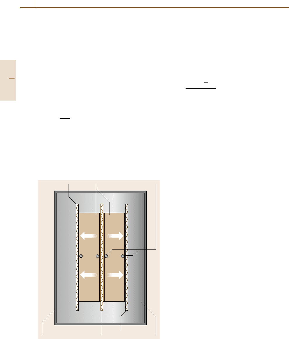
Pipe and Hot Wire Method
The characteristic of this class of methods is radial heat
flow in a cylindrical sample (diameter d
1
, length l). Fig-
ure 8.3 shows the principle of the pipe method.
A hole on the central axis of the sample con-
tains the core heater (diameter d
2
), which is a rod,
Muffle heater Specimen
Temperature sensors
Water cooled
cylindrical chamber
InsulationCore heater
Muffle heater
Fig. 8.3 Principle of the pipe method
tube or wire. Depending on the temperature range of
interest the sample is surrounded by a liquid-cooled
heat sink or a combination of muffle heater and water
jacket. Axial heat losses can be minimized by additional
end guard heaters or a special sample geometry, i. e.
a large length-to-diameter ratio. The thermal conduc-
tivity is determined by the measurement of the radial
heat flow Φ and the temperature difference between the
inner and the outer surface of the sample according to
λ =
Φ ln
d
2
d
1
2πl (T
1
−T
2
)
. (8.10)
Because of its simple design modified versions of this
technique have been used for solids covering the ther-
mal conductivity range between insulation materials
20 mW m
−1
K
−1
and metals
200 W m
−1
K
−1
for
temperatures between room temperature and 2770 K.
Transient modifications to this technique for the simul-
taneous determination of thermal conductivity and ther-
mal diffusivity are of increasing interest (Sect. 8.1.2).
8.1.2 Transient Methods
With the availability of modern computers and data
acquisition systems transient methods have become in-
creasingly popular. The advantages of transient methods
are that much less time is needed for the experiments
and that various thermal properties can be determined
in the same measurement cycle. A typical measurement
duration of one hour for steady-state methods is reduced
to a few minutes or to a subsecond interval for transient
methods. In many cases the temperature measurement
at two opposite surfaces of the sample is replaced by
a temperature measurement as a function of time at only
one position. This makes the design of instruments for
transient measurements straightforward in comparison
to steady-state methods and can improve the accuracy
of the results.
Transient Hot Wire and Hot Strip Method
Most thermal conductivity measurements of liquids,
gases and powders are carried out by means of the tran-
sient hot wire method, a modification of the steady-state
pipe method with a cylindrical specimen geometry and
radial heat flow. The pipe is replaced by a thin platinum
wire or nickel strip [8.2,3]. For measurements on solids
the wire is embedded in grooves between two equally
sized specimens. Considerable care is needed in the
sample preparation to achieve sufficiently low thermal
contact resistances between solid samples and the heat-
ing wire. Therefore, the use of a thin metal foil strip (hot
Part C 8.1
Thermal Properties 8.1 Thermal Conductivity and Specific Heat Capacity 459
strip method) instead of the heating wire has become in-
creasingly popular for measurements on solids. In this
case the sample preparation is simplified by the use of
a heat sink compound. The disadvantage of deviations
from the radial symmetric temperature field in compar-
ison to the wire method is compensated by an adequate
mathematical model and evaluation procedure [8.2,4,5].
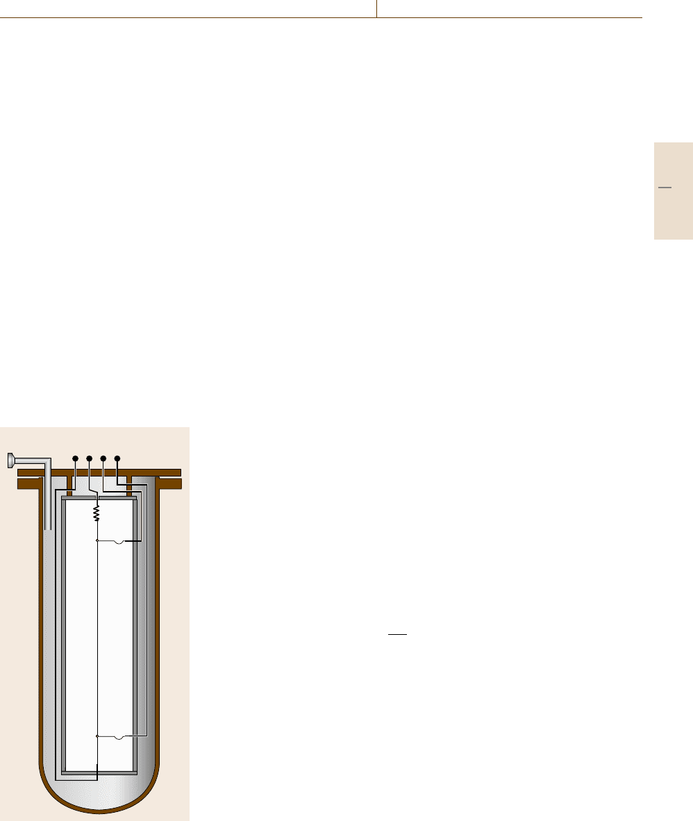
In the standard transient hot wire technique
(Fig. 8.4) the platinum wire has two functions, as
a heater and as a temperature sensor.
The heat source is assumed to have a constant out-
put, which is ensured by a stabilized electrical power
supply. From the slope of the resulting linear tem-
perature rise as a function of elapsed time the thermal
conductivity λ of the specimen is determined. The ther-
mal diffusivity a can be found from the intercept of
this linear temperature dependence. To eliminate the
effect of axial conduction via the large-diameter cur-
rent supply leads attached to the ends of the hot wire,
two hot wires of differing lengths are often operated
in a differential mode. Further modifications of this
technique are the cross-wire and the parallel-wire tech-
niques, where the heater and temperature sensor are
separated from each other. For the cross-wire technique,
IU
Fig. 8.4 Principle
of the hot wire
method
the heating wire and legs of a thermocouple are in di-
rect contact with each other and form a cross. The
advantage of the parallel wire method is that it can be
used for anisotropic materials and for materials having
a thermal conductivity above 2 W m
−1
K
−1
. Further de-
velopments are the use of modulated heat input, e.g.
pulse or sinusoidal modulation.
Relative expanded (k =2) uncertainties of the meas-
ured values of 0.38% for thermal conductivity and 1.7%
for thermal diffusivity (resp. ρc
p
) of liquids have been
achieved [8.5].
Laser Flash Method
The most frequently used method for the determina-
tion of thermal transport properties of solids is the laser
flash method. The main reason is that it can be used
in a wide temperature and thermal diffusivity range.
Measurements in a temperature range between −100
◦
C
and about 3000
◦
C are possible. In contrast to most
other methods different material classes, such as poly-
mers, glasses, ceramics and metals, can be investigated
without significant limitations on the achievable mea-
surement uncertainty.
Using this method the thermal diffusivity a is deter-
mined. If the specific heat capacity and the density of
a material are known, the thermal conductivity can be
calculated by using (8.4). Therefore, thermal diffusivity
measurements are often supplemented by calorimetric
measurements for the determination of the specific heat
capacity.
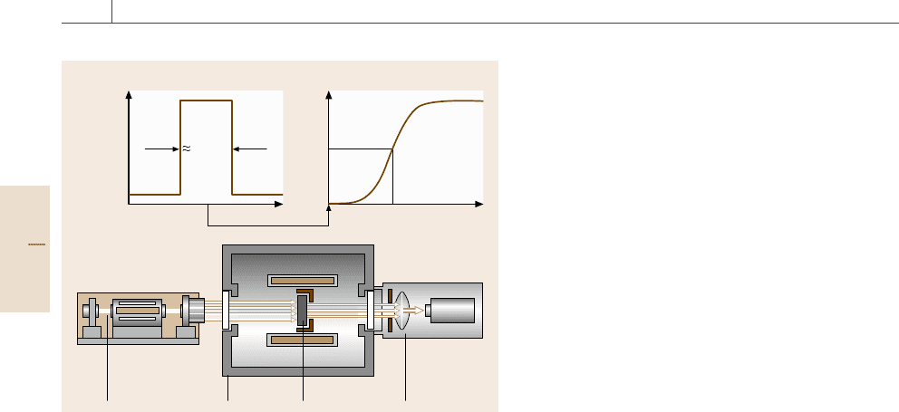
The principle of the laser flash method is based on
the heating of a specimen by a short laser pulse on
the front side of the specimen and the detection of the
temperature increase at its rear side (Fig. 8.5).
If the laser pulse can be considered to be instanta-
neous and if the sample is kept at adiabatic conditions,
the thermal diffusivity a can be calculated according to
a =0.1388
d
2
t
1/2
. (8.11)
The thermal diffusivity is calculated from the thick-
ness d of the specimen (typically 2 mm) and the
time t
1/2
. This is the time needed for the temperature
of the rear specimen surface to reach half its max-
imum value. Several improvements of the evaluation
methods have been developed since the introduction of
this method by Parker et al. in 1961 [8.6]. These are
the consideration of three-dimensional heat flow, heat
losses, finite pulse duration, nonuniform heating, com-
posite structures and radiation contributions to the heat
transfer. In addition several modifications, e.g. for the
Part C 8.1
460 Part C Materials Properties Measurement
500νs
Laser power Temperature
Time
Time
5 ms–10s
t
1/2
Laser SpecimenFurnace
Radiation
thermometer
Fig. 8.5 Principle of the laser flash method
measurement of the specific heat capacity or for the
direct determination of the thermal conductivity, have
been developed.
The most important advantage of the laser flash
method is that, for the determination of a thermal
property, neither absolute temperatures nor heat meas-
urements are necessary. The thermal diffusivity mea-
surement is carried out by determination of the relative
temperature change as a function of time only. This is
the main reason why relative measurement uncertain-
ties in the 3–5% range can be achieved even at high
temperatures [8.7–9].
Photothermal Methods
The principle of these methods is based on the investi-
gation of a light-induced change in the thermal state of
a material in solid, liquid or gaseous state. If light is ab-
sorbed by a sample, subsequent changes in temperature,
pressure or density are detected. There are methods in
which the sample is in contact with the detection system
and others that involve remote, noncontact detection
systems.
Photothermal and photoacoustic methods for the de-
termination of optical absorption and thermal properties
of materials can be classified according to the detection
technique used. These are based on the measurement of
changes in:
•
Temperature: Changes in temperature are usually
investigated by means of contact thermometry (e.g.
the photopyroelectric technique), radiation ther-
mometry or calorimetric methods.
•
Pressure: Pressure changes are determined via
acoustic methods.
•
Density: The investigation of density changes in-
clude the detection of refractive index variations or
of surface deformations. The most important tech-
niques are the thermal lens method, thermal wave
technique, beam deflection, refraction or diffraction
methods.
The general idea of thermal diffusivity measurement by
photothermal methods is modulated heating of a sample
surface and detection of the amplitude and phase of the
temperature at the opposite sample surface as a func-
tion of modulation frequency. This technique can be
modified by simultaneous heating of both surfaces with
a single modulation frequency and measurement of the
phase difference between both surface signals.
Photoacoustic Technique. Typically the sample is
placed in an acoustically sealed cell containing a con-
tact gas and a microphone. A monochromatic light
source periodically heats the sample and the resulting
expansion causes a pressure wave which is sensed with
the microphone pressure transducer. Liquid or solid
samples can be measured either by direct coupling of
the acoustic wave to the microphone or via a gas (cou-
pling fluid). A great variety of photoacoustic configura-
tions have been developed depending on the aggregate
state of the sample, the property to be measured (e.g.
thermal diffusivity, effusivity, optical properties) or the
temperature and pressure range of interest.
Optical Beam Deflection Technique. An excitation
beam heats the material periodically while a continuous
wave (cw) probe beam is used either in order to detect
density changes of the gas near the sample surface or
to probe the sample directly. Depending on the relative
position between excitation and probe beam, collinear
and perpendicular configurations are distinguished. If
the sample surface temperature is different from that of
the surrounding gas, this results in a temperature gra-
dient between the gas near the sample surface and the
bulk gas. Since the density of a gas is temperature de-
pendent, a gradient of the refractive index of the gas is
observed. This method, also known as the optical mi-
rage technique, is based on the refraction of the probe
beam caused by the dependence of the speed of light on
the gas temperature.
Part C 8.1

Thermal Properties 8.1 Thermal Conductivity and Specific Heat Capacity 461
Thermal Lens Technique. This method is of particu-
lar interest for the determination of thermal properties
of transparent liquids and solids, such as glasses, poly-
mers or liquid crystals. The photothermal lens is created
through the temperature dependence of the refractive
index of the sample resulting from the heating of the
sample by an excitation laser beam. Typically the lens
causes a laser beam divergence which is detected as
a time-dependent decrease in power at the center of the
beam.
Thermal Wave Technique. The principle of the thermal
wave technique is based on measurements of tempera-
ture fluctuations in a (gaseous) sample following the
absorption of intensity-modulated light. The thermal
diffusivity is determined from frequency- and time-
domain behavior of a thermal wave in a fixed volume.
An improvement of this technique is the development
of the thermal wave resonant cavity, which has been
used for the measurement of the thermal diffusivity of
gases with very high precision. A thermal wave cav-
ity consists of two parallel walls. One wall is fixed
and periodically heated by a laser beam or resistive
heating. The other one consists of a pyroelectric thin-
film transducer, which is used to monitor the spatial
behavior of the thermal wave by means of cavity-
length scans. By this method the thermal conductivity
and thermal diffusivity of the gas in the cavity can be
measured.
For a more detailed discussion we refer to [8.10].
8.1.3 Calorimetric Methods
The general principle of all calorimetric methods for
the determination of the specific heat capacity is based
on (8.1), i. e. the measurement of a specific amount of
heat dQ and the resulting temperature increase dT.In
most cases two experiments are necessary, a first one
with the empty calorimeter in order to determine the in-
strument’s heat capacity and for the correction of the
remaining heat losses and a second one with the filled
calorimeter including the sample.
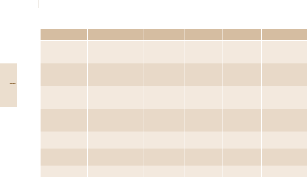
Numerous types of calorimeters have been devel-
oped for the determination of specific heat capacities of
materials. Table 8.2 shows the most important of these
and their typical application range.
The most accurate methods for specific heat cap-
acity measurements are adiabatic calorimetry and drop
calorimetry (for details see Sect. 8.2). Construction of
these high-precision instruments, which are not com-
mercially available, requires considerable effort and
money, while their operation demands substantial ex-
perience and time.
Therefore, probably more than 90% of specific heat
capacity measurements of solids and liquids are car-
ried out by means of a differential scanning calorimeter
(DSC, for a detailed description see Sect. 8.2.2). A DSC
is operated in dynamic mode, which means that the fur-
nace is heated or cooled with a constant scanning rate
of, typically, 20 K/min. The measured quantities are
the heat flow rate Φ = dQ/ dt and the corresponding
sample temperature T. Usually, three experiments are
necessary: the measurement of the empty calorimeter,
the sample measurement and the calibration sample
measurement.
A calibration is needed because differential scan-
ning calorimetry is a relative method. There are two
materials that are considered as standards for the test or
calibration of calorimeters used for the determination of
specific heat capacities of solids. These are copper for
the temperature range 20–320 K [8.11] and synthetic
sapphire for the temperature range 10–2250 K [8.12].
The relative measurement uncertainties are less than
0.1% for copper, and less than 0.1% for sapphire in the
temperature range 100–900 K and in the range 1–2% at
higher temperatures.
In many cases a certified reference material such as
synthetic sapphire (e.g., SRM 720 from the National
Institute of Standards and Technology, Gaithersburg,
USA) is used as the calibration material.
If the heating rates of the sample (s), calibration
sample (cal) and empty (0) measurement are identical,
the specific heat capacity of the sample c
p,s
is given by
c
p,s
=
m
cal
c
p,cal
m
s
Φ
s
−Φ
0
Φ
cal
−Φ
0
. (8.12)
Here m
s
and m
cal
are the masses of the sample and
calibration sample and the corresponding heat flow
rates are Φ
s
and Φ
cal
. There are several commer-
cially available instruments that can be used in different
temperature ranges between 100 K and 1900 K. For
most DSCs disk-typed samples with diameters of about
6 mm and heights of 1 mm are used. But there are
also cylinder-type DSCs (known as Calvet-type de-
vices) having sample container volumes in the range
1.5–150 ml. For measurements on liquids a measure-
ment or control of the vapor pressure and of the sample
volume is necessary. This is carried out by special sam-
ple cells in cylinder-type instruments or DSCs specially
developed for the purpose.
The typical measurement uncertainties of specific
heat capacity measurements of solids by means of DSCs
Part C 8.1
462 Part C Materials Properties Measurement
Table 8.2 Different types of calorimeters used for the determination of specific heat capacities
Type of calorimeter Quantities Typical tempera-
ture range (K)
Uncertainty
(%)
Merit Demerit
Differential scanning
calorimeter
Specific heat capacity,
enthalpy of phase
transition of solids and
liquids
100–1900 1.5–10 Standardized,
easy to use, fast
Relative method
Adiabatic calorimeter Specific heat capacity,
enthalpy of phase
transition of solids, liquids
and gases
1–1900 0.05–2 High accuracy Long measurement
time, expensive
Drop calorimeter Specific heat capacity,
enthalpy of phase
transition of solids and
liquids
273–3000 0.1–2 High accuracy Expensive
Pulse calorimeter Specific heat capacity,
enthalpy of phase
transition of solids and
liquids
600–10 000 2–3 Fast, high
temperature
Only electrically
conducting
materials, expensive
Flow calorimeter Specific heat capacity and
enthalpy measurements of
liquids and gases
100–700 0.05 − −
Bomb calorimeter Heat of combustion of
solids, liquids and gases
300 0.01 Standard method
for solids, liquids
Low accuracy for
gases
Gas calorimeter Heat of combustion of
gases
300 0.03–0.5 Standard method
for gases
−
are about 5% below 700
◦
C and up to 10% at high
temperatures. A higher accuracy requires considerable
more time and effort to be spent on a proper calibra-
tion and evaluation procedure. In those cases a relative
uncertainty of about 1.5% is achievable using this tech-
nique [8.13].
At high temperatures there are considerable prob-
lems with most calorimetric techniques due to heat
losses by thermal radiation, mechanical, electrical or
chemical properties of the sample and the construction
material of the calorimeters. Therefore, for measure-
ment at temperatures above 2000 K, pulse calorimetry
is advantageous [8.1, 14], but can only be used for ma-
terials having a sufficiently high electrical conductivity.
The principle of the pulse method is based on a rapid re-
sistive self-heating of a rod- or wire-type specimen by
the passage of an electrical current pulse through it. For
the determination of the specific heat capacity measure-
ments of the current through the specimen (typically in
the range 100–10 000 A), the voltage drop across the
specimen and of the specimen temperature with submil-
lisecond resolution are necessary. If the heating rate is
sufficiently large, investigations in the liquid state are
possible. Modifications of this technique allow the ad-
ditional determination of the emissivity, the electrical
and thermal conductivity and of the enthalpy of fusion.
The temperature range of this technique is ap-
proximately 600–10 000 K. For specific heat capacity
measurements by pulse calorimetry relative uncertain-
ties of 2–3% can be achieved.
8.2 Enthalpy of Phase Transition, Adsorption and Mixing
According to the first law of thermodynamics the
change in the internal energy of a thermodynamic sys-
tem dU is equal to the difference between the heat
transfer into the system dQ and the mechanical work
done by the system dW (other energy forms are ne-
glected here).
dU = dQ + dW = dQ − pdV
(8.13)
The enthalpy of a thermodynamic system is defined
according to H =U + pV and the resulting enthalpy
change dH is
dH = dU +pdV +V dp = dQ +V dp . (8.14)
Equation (8.14) describes the relationship between
the measured quantity, the exchanged heat dQ,and
the quantity assigned to the material, the enthalpy
Part C 8.2

Thermal Properties 8.2 Enthalpy of Phase Transition, Adsorption and Mixing 463
change dH. The relationship between these quantities
as a function of the variables of state, namely pres-
sure p, temperature T and composition ξ, is given by:
dQ =
∂H
∂p
−V
T,ξ
dp
+
∂H
∂T
p,ξ
dT +
∂H
∂ξ
T, p
dξ. (8.15)
In many cases the pressure change is very small and
the first term of (8.15) is negligible. The second term
is the heat capacity at constant pressure of nonreact-
ing systems. The third term describes the isothermal
and isobaric enthalpy change due to phase transitions,
mixing or chemical reactions. At constant pressure and
in the absence of other energy conversions (e.g. defor-
mation, oxidation or surface energy transformation) the
enthalpy of transition of a material Δ
trs
H is equal to the
heat of transition Q
trs
.
To understand the general principles of calorimetric
measurements it is helpful to separate a calorimeter into
three parts: (a) the calorimeter vessel with sample, cru-
cible, thermometer and additional equipment for heat
measurement, (b) the immediate surroundings of the
calorimeter vessel, e.g. a temperature-controlled liquid
bath or metal block and (c) a means for initiation chem-
ical reactions, mixing, solution or adsorption processes.
Often a calorimeter is characterized according to its
mode of operation, being either adiabatic, isothermal
or isoperibol. Adiabatic means that the heat exchange
between calorimeter vessel and surroundings is consid-
ered to be zero. In isothermal mode the temperature
of the calorimeter vessel remains constant. In isoperi-
bol mode the temperature of the surroundings is kept
constant.
There are numerous types of calorimeters in use
and, as a consequence, several classification systems
have been proposed. Typical criteria for the classifica-
tion are the following:
Principle of (Heat) Measurement.
•
Heat-compensation calorimeters
The heat to be measured is determined, e.g., by
Joule heating, Peltier cooling or by means of the
latent heat of a phase transition (e.g., Bunsen ice cal-
orimeter). The measurements are mostly carried out
under isothermal or quasi-isothermal conditions.
•
Heat-accumulation calorimeters
The heat is determined by means of a temper-
ature change measurement. It is based on the
fact that the temperature increase of a calorime-
ter is proportional to the amount of heat added.
The proportionality factor must be determined by
calibration with a known amount of heat. This prin-
ciple of measurement requires the minimization of
heat losses. Therefore, measurements are prefer-
ably carried out under adiabatic or quasi-adiabatic
conditions.
•
Heat-conduction calorimeters
In this type of calorimeter the heat is exchanged
between the calorimeter and its surroundings via
a well-defined heat conduction path. The corres-
ponding heat flow rate (with dimensions of power)
is measured, e.g., by means of heat flux sensors
(thermopiles). Heat is determined by integration
of the measured heat flow rate as a function of
time. Instruments of that type are often operated
at isoperibol conditions, i. e. the temperature of the
surroundings remains constant.
Mode of Operation.
•
Static mode
This mode includes adiabatic, isothermal or isoperi-
bol operation.
•
Dynamic mode
Either the temperature of the calorimeter vessel
or that of the surroundings is changed. The linear
scanning mode (constant heating rate) is most of-
ten used, i. e. the temperature of the calorimeter
vessel is a linear function of time. During recent
years an increasing number of variable heating rate
techniques was developed. Typical modes of oper-
ation are stepwise heating or the superposition of
a constant heating rate by sinusoidal or sawtooth
temperature changes.
Construction Principles. These are single, twin or dif-
ferential calorimeters.
Methods of Reaction, Solution, Mixing or Adsorp-
tion Initiation. Examples are continuous (e.g. flow
calorimeters), discontinuous or incremental working in-
struments (e.g. incremental titration).
The use of certified reference materials or pure
substances with well-known thermodynamic proper-
ties [8.15–18] to check the proper functioning of
a calorimeter, the calibration of the instrument, and
for validation of the reliability of the measurement
uncertainty budget is highly recommended. Certified
reference materials for calorimetry are available from
the National Institute of Standards and Technology
(NIST, USA), the Physikalisch-Technische Bundes-
Part C 8.2
464 Part C Materials Properties Measurement
anstalt (PTB, Germany) and the Laboratory of the
Government Chemist (LGC, UK).
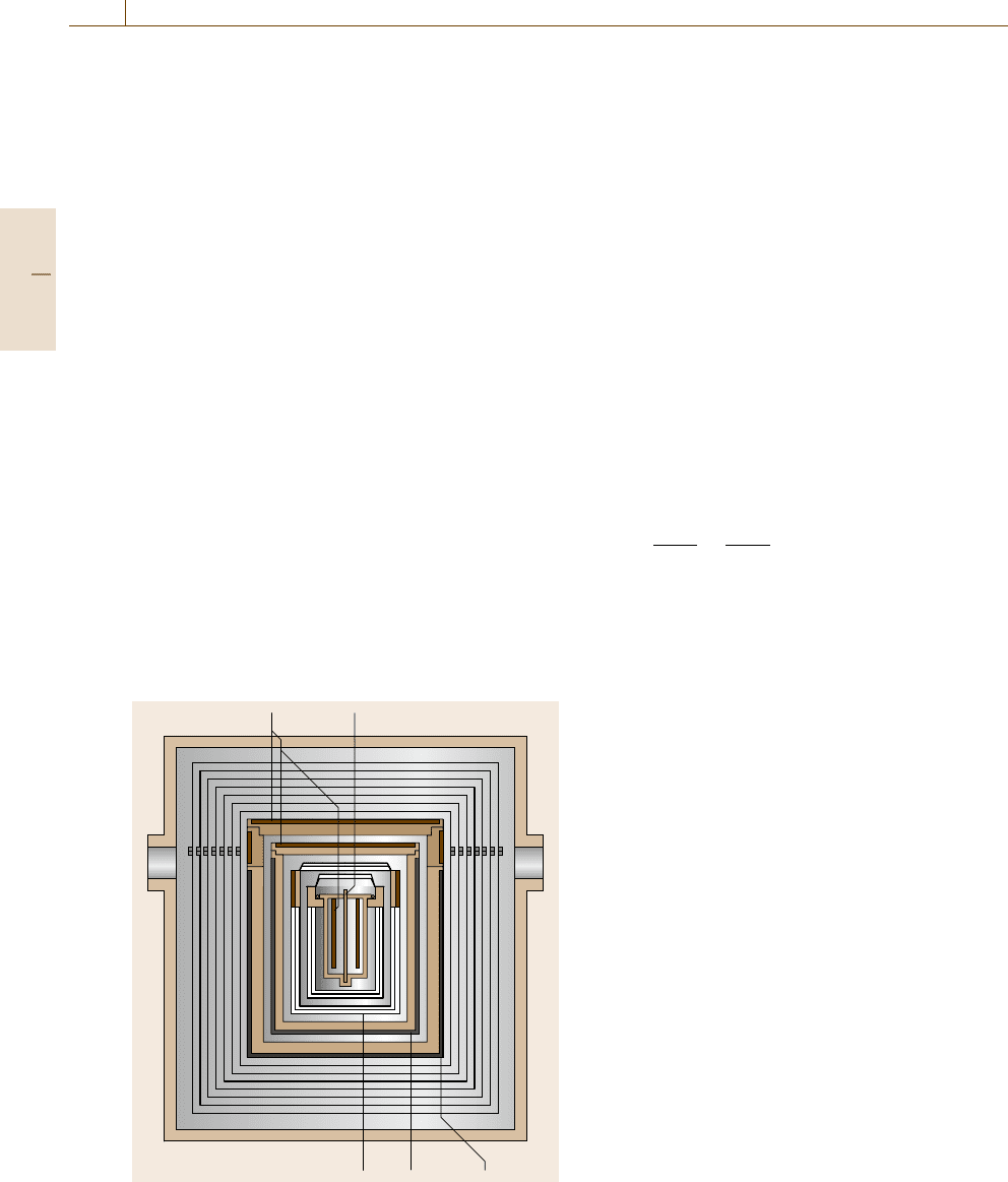
8.2.1 Adiabatic Calorimetry
Adiabatic calorimetry is one of the most accurate ther-
mal methods. Relative uncertainties of less than 0.1%
for enthalpy of fusion or specific heat capacity measure-
ments can be achieved. To reach this level, substantial
expenditure on the construction, measurement and con-
trol of the system is required [8.19, 20]. Typically an
adiabatic calorimeter can be divided into three parts:
a cylindrical inner part surrounded by a system of adia-
batic shields and a furnace (Fig. 8.6).
The inner part of the calorimeter consists of a ther-
mometer, crucible(s), sample, heater and inner radiation
shields. In contrast to other calorimeters standard plat-
inum resistance thermometers are mostly used. This
allows the determination of transition temperatures with
the highest accuracy (ΔT ≈ 1mK).
For the realization of adiabatic measurement con-
ditions (prevention of heat exchange with the surround-
ings) the inner sample part of the calorimeter is enclosed
by a heated adiabatic shield, controlled to the same tem-
perature as the inner part. For proper control of the
adiabatic conditions and to ensure sufficient tempera-
ture homogeneity further guard and radiation shields
Heater Thermometer
Adiabatic shield
Furnace
Guard
Fig. 8.6 Principle of an adiabatic calorimeter
are concentrically arranged around the adiabatic shield.
The outer part of an adiabatic calorimeter is the furnace
(or cryostat) and an enclosure for measurements in vac-
uum or at controlled inert gas flow. To minimize heat
losses and temperature gradients within the calorimeter,
construction materials must have a very high thermal
conductivity and low emissivity in the infrared range
(e.g. silver).
The basic principle of adiabatic calorimetry is the
measurement of the temperature increase of the sam-
ple due to the supply of a known amount of heat.
Therefore, the typical mode of operation consists of al-
ternating heating and equilibration periods, but there are
also several adiabatic calorimeters that operate in scan-
ning mode at very low scanning rates. Under adiabatic
conditions the enthalpy increment is equal to the sup-
plied heat, which is determined by an electrical energy
measurement of high accuracy (P
el
t = Q, P
el
:power,
t: time). Determination of the specific heat capacity of
a material is reduced to the basic relation
c
p
=
Q
mΔT
=
P
el
t
mΔT
. (8.16)
In real measurements very small heat losses remain,
which can be determined and corrected by means
of additional experiments. For that purpose in a first
empty run the heat capacity of the calorimeter without
a sample is measured. In a properly designed adiabatic
calorimeter the heat losses are equal in the empty and
filled state. Therefore, the empty measurement is also
the basis for the correction of the remaining heat losses.
A measurement procedure for the determination of
the enthalpy of fusion also consists of different runs and
again a step heating procedure with alternating heat-
ing and equilibration periods is used. For experimental
reasons each fusion experiment starts below and stops
above the fusion temperature. Therefore, the heat cap-
acity contributions of the (filled) calorimeter must be
considered. Further experiments are needed to deter-
mine the fusion temperature of the material. For that
purpose the method of fractional fusion is used.
Adiabatic calorimeters are used from temperatures
below 1 K up to about 1900 K [8.21]. At high tempera-
tures the main problems are deviations from adiabatic
conditions because of thermal radiation. This results in
measurement uncertainties of a few percent for enthalpy
of fusion and specific heat capacity measurements at
temperatures above 1000 K. In the low-temperature
range the specific heat capacity of materials and the
sensitivity of most high-precision thermometers rapidly
decrease as a function of temperature. This leads to the
Part C 8.2
Thermal Properties 8.2 Enthalpy of Phase Transition, Adsorption and Mixing 465
requirement for considerable effort for the measurement
of the temperature difference of the sample and for the
control of the adiabatic shield. The lowest uncertainties
for enthalpy of fusion measurements of less than 0.1%
are achieved in the 100–900 K range.
8.2.2 Differential Scanning Calorimetry
Differential scanning calorimeters (DSCs) are twin-
type systems consisting of identical measuring systems
for the sample and a reference sample [8.22]. These
are mounted in the same furnace and commonly sub-
jected to a controlled temperature program (heating or
cooling). During heating or cooling heat is exchanged
between the furnace and sample part of the calorim-
eter (corresponding heat flow rate Φ
FS
) and in the same
manner between the furnace and reference part of the
calorimeter (corresponding heat flow rate Φ
FR
). The
difference between these heat flow rates (ΔΦ =Φ
FS
−
Φ
FR
) is measured and used for the determination of the
quantity of interest, e.g. the enthalpy of fusion of the
sample. A differential scanning calorimeter measures
two quantities, the heat flow rate ΔΦ (with dimensions
of power) and the corresponding sample temperature.
For the measurement of temperatures either platinum
resistance thermometers or thermocouples are used.
Heat flow rates are measured either by direct electrical
power measurements or by means of thermocouples or
thermopiles. The use of thermocouples or thermopiles is
based on the determination of a temperature drop across
a thermal resistor, in analogy to the determination of
electrical currents by the measurement of the voltage
drop across an ohmic resistor.
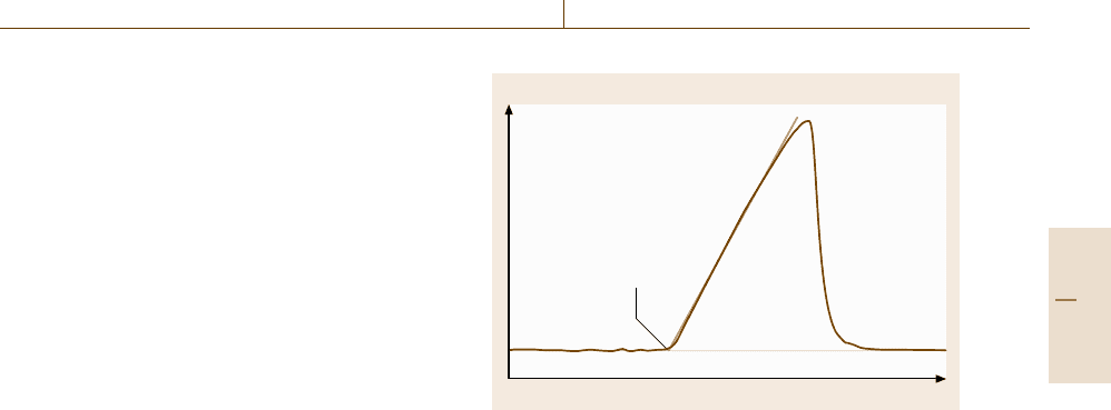
Using DSC, both the determination of a transition
temperature and the determination of a heat of transition
is possible. The transition temperature is determined
from the extrapolated peak onset temperature T
e
and the
transition enthalpy from the peak area of the heat flow
rate curve (Fig. 8.7).
To determine the peak area the baseline must be sub-
tracted. The proper choice of the baseline has a major
influence on the measurement uncertainty of the transi-
tion enthalpy.
A further feature of differential scanning calorime-
try is the dynamic mode of operation. Typically
a temperature program consists of three segments:
an initial isothermal segment, followed by a scan-
ning segment (heating or cooling) with a constant rate
and a final isothermal segment. Scanning rates in the
range ±0.1–500 K/min in a temperature range between
−150
◦
C and 1600
◦
C are used for the determination
Heat flow rate
Time
T
e
Fig. 8.7 Heat flow rate signal of a DSC during a transition
in heating mode with extrapolated peak onset tempera-
ture T
e
of enthalpies of phase transitions and specific heat
capacities.
A further development is the variable heating rate
DSC, where a temperature modulation is superimposed
on the constant heating or cooling rate of a conven-
tional DSC. The simplest and most commonly used
modulation type is periodic, e.g. sinusoidal, sawtooth
or stepwise heating. This technique has been success-
fully applied for the separation of superimposed effects
such as glass transitions and enthalpy relaxations or the
determination of specific heat capacities during phase
transitions.
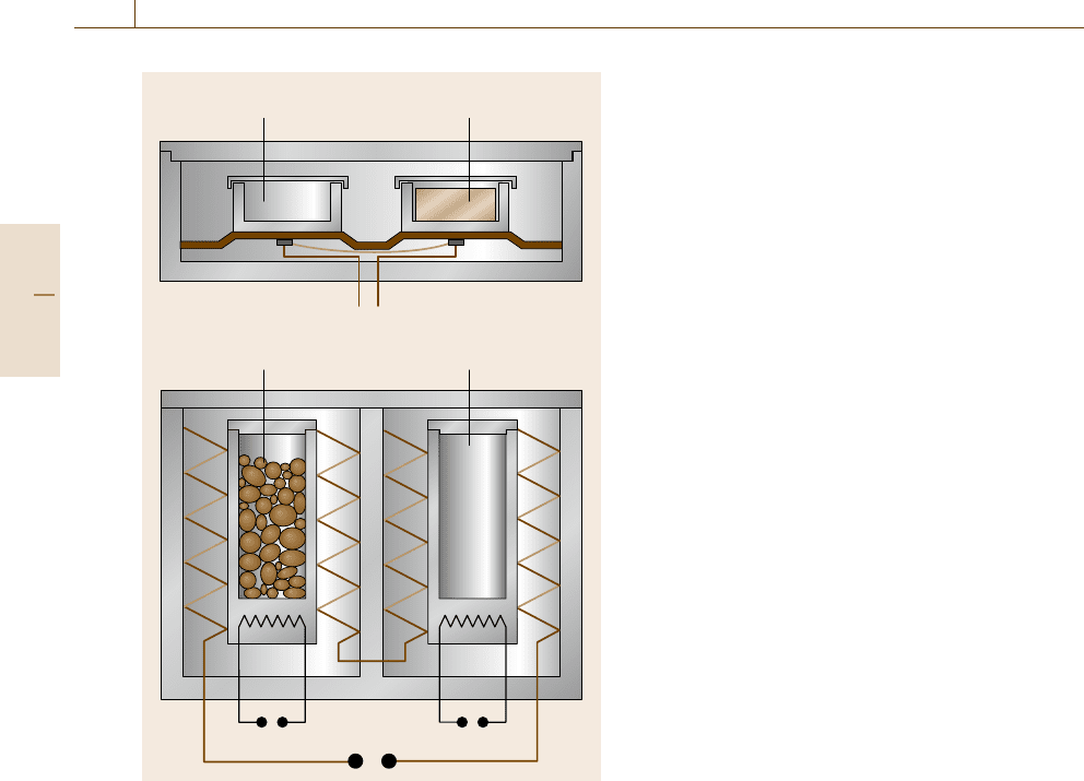
There are two basic types of DSCs, the heat flux
DSC and the power compensation DSC. The principle
of the heat flux type of DSC is based on the measure-
ment of the difference of the heat flow rates ΔΦ as
described above. The heat flux within the DSC takes
place via a well-defined heat conduction path with low
thermal resistance. There are two different principles of
construction of heat flux DSCs, namely disk-type and
cylinder-type systems (Fig. 8.8).
A power compensation DSC consists of two iden-
tical microfurnaces (for sample and reference sample)
which are heated separately according to a prescribed
temperature program. The temperature difference be-
tween the two microfurnaces is measured and controlled
to achieve the same program of temperature versus time
for the sample and reference sample. The compensat-
ing heating power is a measure of the heat flow rate
difference ΔΦ.
Several modified DSCs have been developed for
special applications. Among these are the high-pressure
DSC [8.23], photo DSCs for the investigation of light-
Part C 8.2
466 Part C Materials Properties Measurement
Disk-type DSC
Cylinder-type DSC
Reference Sample
U
Th
~Δ
ReferenceSample
U
Th
~Δ
Fig. 8.8 Different types of heat flux DSCs
induced reactions [8.24]andDSCs for measurements
on fluids [8.25, 26]. Cylinder-type instruments can be
modified to investigate mixing, solution or adsorption
processes.
The basic requirement for reliable measurements
by means of DSC is the calibration of the instrument,
for several reasons. These are the possible drift of sen-
sors and other parts of the measuring system but more
importantly the dependence of the calibration on tem-
perature, heating rates, sample holder and crucible or
sample properties, e.g. mass, thermal conductivity. It
is generally recommended that the calibrations be car-
ried out at conditions similar to those of the actual
measurement. A typical example is the heat flow rate
calibration. In principle, a cylinder-type DSC could be
calibrated using a number of methods, e.g. electrically
by means of a calibration heater, by means of a refer-
ence material with known specific heat capacity or by
means of a material with known enthalpy of fusion. One
would expect it to be sufficient to calibrate the instru-
ment by any of these methods. But, depending on the
actual measurement problem, very different measure-
ment uncertainties would be achieved. Therefore, the
German Society for Thermal Analysis (GEFTA) recom-
mends [8.15, 27] to distinguish between the heat and
the heat flow rate calibration of a DSC, even though
the same sensor and electronics are used for both types
of measurement. As an example, if the enthalpy of
fusion of an unknown material is measured, a heat cal-
ibration of the DSC by means of a reference material
with known enthalpy of fusion at a temperature close
to the fusion temperature of the unknown material is
recommended.
A metrologically flawless calibration of a DSC is
very time consuming but can improve the accuracy of
results by about one order of magnitude. Basic require-
ments for DSC calibrations are given by international
standards and more detailed procedures have been pub-
lished by GEFTA or the International Confederation for
Thermal Analysis and Calorimetry.
With carefully calibrated instruments relative meas-
urement uncertainties of about 1% for enthalpy of
fusion measurements and 1.5% for specific heat cap-
acity measurements can be achieved. For routine work
relative uncertainties in the 5–10% range are more
typical.
8.2.3 Drop Calorimetry
Drop calorimeters are used for the determination of en-
thalpy increments and specific heat capacities of solid or
liquid materials in a temperature range between room
temperature and more than 3000 K. The only require-
ments are that the sample should be nonreactive with its
container and have a low vapor pressure to avoid mass
loss and significant contributions from heat of reaction
or vaporization.
The basic principle of a drop calorimeter is the
rapid translation (drop) of a sample from some exterior,
temperature-controlled zone (furnace) with tempera-
ture T
1
into a calorimeter with temperature T
2
,which
is used for the measurement of the heat transfered.
If the instrument is properly designed then the
heat loss during the translation from the furnace to
the calorimeter is negligible and relative measurement
uncertainties of less than 0.1% are possible [8.28].
A disadvantage of that technique is that an initial
cooling rate of the sample of up to 2000 K/s is pos-
sible. In that case the sample might become frozen in
a metastable state.
Part C 8.2
Thermal Properties 8.2 Enthalpy of Phase Transition, Adsorption and Mixing 467
The calorimeter is typically an adiabatic, isoperi-
bol or isothermal instrument. These can be considered
as consisting of two parts: the central measuring part
and its enclosing surroundings. In adiabatic calorime-
ters at any time the temperature of the surroundings
is controlled to the same value as that of the cen-
tral (sample) measuring part. Consequently, no heat
losses occur (adiabatic conditions), and adding of
heat results in a temperature increase that is used
as a measure of that heat. The relationship between
heat and temperature increase and the heat capacity
of the empty calorimeter are determined by electrical
calibrations.
An isoperibol mode of operation means that the
temperature of the surroundings is kept constant. In
that case two processes occur, if heat is added, firstly
the temperature of the calorimeter is increased (heat is
stored) and secondly heat is exchanged with the sur-
roundings. The lowest measurement uncertainties are
achieved if the amount of stored heat is considerable
larger than the exchanged heat.
Several methods are in use for the determination of
the heat loss correction. These are based on the validity
of Newton’s law of cooling
dT
2
/dt =−k(T
2
−T
1
)
.
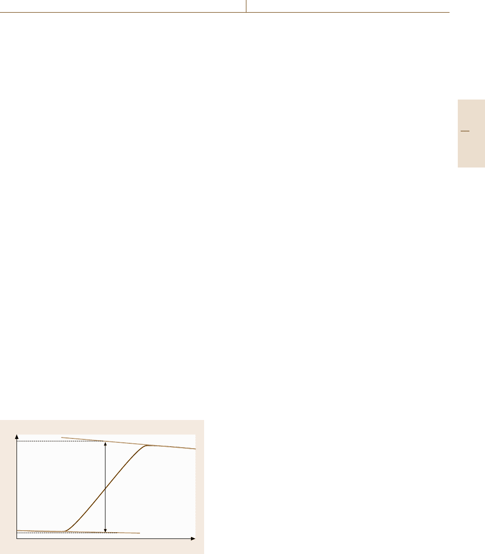
The basic idea of most methods for the correction of
heat losses in adiabatic and isoperibol calorimeters is
the back and forward extrapolation of the final and ini-
tial temperatures over time (Fig. 8.9). This allows the
determination of the adiabatic temperature difference
ΔT
adiab
(without heat losses) at the time where areas A
1
and A
2
are equal.
In a calorimeter working in isothermal mode, both
the temperature of the surroundings T
s
and the tempera-
ture of the central measuring part T
m
remain constant.
This is achieved by using a thermostat to keep the tem-
Tem p e r a t u r e
Time
T
2
T
1
A
2
A
1
ΔT
adiab
(A
1
= A
2
)
Fig. 8.9 Principle of the heat loss correction based on
Newton’s law of cooling
perature of the surroundings constant and a two-phase
system as the working substance for the measuring
part. Using a two-phase system (usually a solid–liquid
phase transition) for temperature control means that
adding heat to the measuring part of a calorimeter re-
sults in a change of the phase distribution (melting of
some material) at constant temperature. The amount of
melted material is determined either by weighing or
by a volume change measurement. The volume change
measurement is based on density differences of the
working substance between its solid and liquid state
(e.g. Bunsen ice calorimeter). On this basis heat meas-
urements with relative uncertainties of 0.02% have been
made.
8.2.4 Solution Calorimetry
The determination of heat of solution, mixing, or ad-
sorption [8.29] is of interest in different fields of
materials research, e.g. for investigation of polymers,
pharmaceutical products or ceramics. Differences in the
heat of solution between different batches of a ma-
terial can reflect variations in polymorphism, moisture
content, degree of crystallinity, surface area or sur-
face energy. Instruments can be classified according
to the state of aggregation of the interacting materials
or whether a continuous (flow calorimeters) step mode
(e.g. titration) or discontinuous mode of operation is
used.
A further classification scheme is the mode of
operation resulting from the coupling between the cen-
tral part of the calorimeter, which is used for the
caloric measurements, and the surroundings. Solution
calorimeters are operated either in adiabatic, isothermal
or isoperibol mode.
Specific problems are the separation and the tem-
perature control of the components before the start,
complete mixing over the course of the investigations
and the change in the vapor pressure during mix-
ing. Calorimeters for discontinuous operation consist
of a reaction vessel, a thermometer, a mixing unit or
ampoule-breaking system, the stirrer and a resistance
heater for electrical calibration. Typically thermometers
are thermistors, platinum resistance (Sect. 8.5) or quartz
thermometers. The principle of a quartz thermometer is
based on the resonant frequency dependence of a quartz
oscillator as a function of temperature. Often one of the
samples is sealed in a thin-walled glass ampoule. Af-
ter the system is in thermal equilibrium, the solution or
reaction process under study is started by breaking the
glass ampoule.
Part C 8.2