Douglas H. Williams. PDA Robotics. 2003. 256p
Подождите немного. Документ загружается.


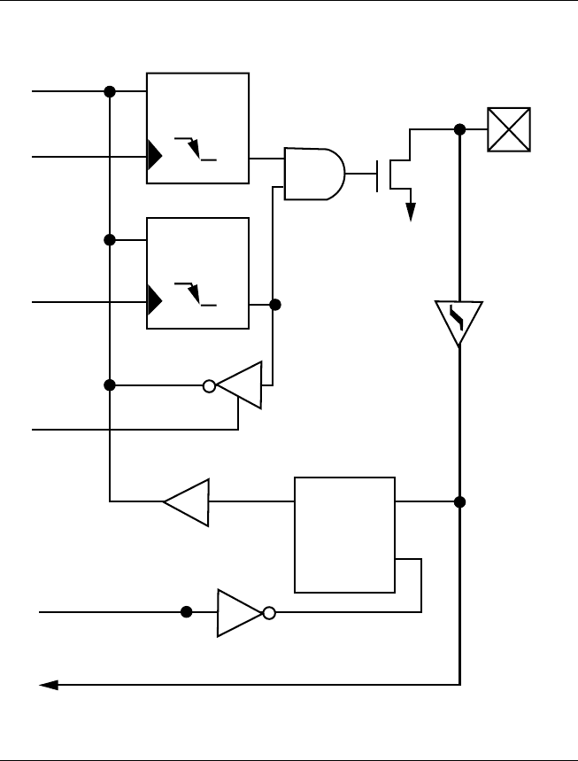
Typical Optical Transceiver Circuit
The optical transceiver logic can be implemented with discrete com-
ponents for cost savings. Care must be taken in the design and layout
of the photo-detect circuit, due to the small signals that are being
detected and their sensitivity to noise.
MCP2150 Absolute Maximum Ratings
Ambient Temperature under bias . . . . . . . . . . . . . . . . . . . . . . . . . . . . –40°C to +125°C
Storage Temperature. . . . . . . . . . . . . . . . . . . . . . . . . . . . . . . . . . . . . –65°C to +150°C
Voltage on VDD with respect to VSS . . . . . . . . . . . . . . . . . . . . . . . . . . –0.3 V to +6.5 V
Voltage on RESET with respect to VSS . . . . . . . . . . . . . . . . . . . . . . . . . –0.3 V to +14 V
Voltage on all other pins with respect to VSS . . . . . . . . . . . . . . . –0.3 V to (VDD + 0.3 V)
Total Power Dissipation (1). . . . . . . . . . . . . . . . . . . . . . . . . . . . . . . . . . . . . . . 800 mW
Max. Current out of VSS pin . . . . . . . . . . . . . . . . . . . . . . . . . . . . . . . . . . . . . . 300 mA
Max. Current into VDD pin . . . . . . . . . . . . . . . . . . . . . . . . . . . . . . . . . . . . . . . 250 mA
Input Clamp Current, IIK (VI < 0 or VI > VDD) . . . . . . . . . . . . . . . . . . . . . . . . . . ±20 mA
Output Clamp Current, IOK (V0 < 0 or V0 > VDD) . . . . . . . . . . . . . . . . . . . . . . . ±20 mA
Max. Output Current sunk by any Output pin . . . . . . . . . . . . . . . . . . . . . . . . . . . . 25 mA
Max. Output Current sourced by any Output pin. . . . . . . . . . . . . . . . . . . . . . . . . . 25 mA
Note 1: Power Dissipation is calculated as follows:
PDIS = VDD x {IDD - ∑ IOH} + ∑ {(VDD-VOH) x IOH} + ∑(VOL x IOL)
NOTICE: Stresses above those listed under “Maximum Ratings” may
cause permanent damage to the device. This is a stress rating only, and
functional operation of the device at those or any other conditions
above those indicated in the operational listings of this specification
is not implied. Exposure to maximum rating conditions for extended
periods may affect device reliability.
Figure 5.30 shows the physical layout of the MCP2150 chip used in
PDA Robot.
PIC16F876: PDA Robot’s Microcontroller
The PIC16F876 is used to send and receive commands from the robot
to the PDA, get analog readings from the range finder, and switch the
robot’s motors on and off. I chose this chip because it is low cost, very
fast, can be electronically erased, flashed programmed, and is readily
available.
PDA Robotics
78
PDA 05 5/30/03 11:35 AM Page 78
Chapter 5 / The Electronics
79
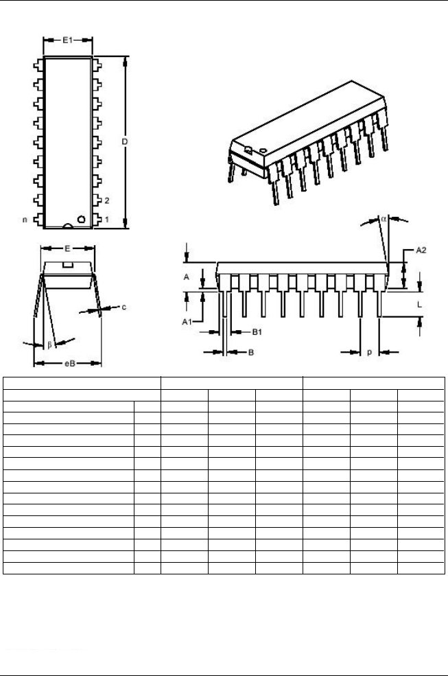
Figure 5.30
MCP2150 DIP physical dimensions used in PDA Robot.
Units INCHES* MILLIMETERS
Dimension Limits MIN NOM MAX MIN NOM MAX
Number of Pins
Pitch
Top to Seating Plane
Molded Package Thickness
Base to Seating Plane
Shoulder to Shoulder Width
Molded Package Width
Overall Length
Tip 10 Seating Plane
Lead Thickness
Upper Lead Width
Lower Lead Width
Overall Row Spacing §
Mold Draft Angle top
Mold Draft Angle Bottom
.140
.115
.015
.300
.240
.890
.125
.008
.045
.014
.310
5
5
18
.100
.155
.130
.313
.250
.898
.130
.012
.058
.018
.370
10
10
18
2.54
3.94
3.30
7.94
6.35
22.80
3.30
0.29
1.46
0.46
9.40
10
10
.170
.145
.325
.260
.905
.135
.015
.070
.022
.430
15
15
3.56
2.92
.038
7.62
6.10
22.61
3.18
0.20
1.14
0.36
7.87
5
5
4.32
3.68
8.26
6.60
22.99
3.43
0.38
1.78
0.56
10.92
15
15
n
p
A
A2
A1
E
E1
D
L
c
B1
B
eB
␣
ß
* Controlling Parameter
§ Significant Characteristic
Notes:
Dimensions D and E1 do not include mold flash or protrusions. Mold flash or protrusions shall not exceed
.010" (0.254mm) per side.
JEDEC Equivalent: MS-001
Drawing No. C04-007
PDA 05 5/30/03 11:35 AM Page 79

The following information about the specifics of this chip from the
data sheets explains the details of its inner workings. I highly recom-
mend going to www.microchip.com to download any updates. There
is enough information provided in the sheets to write a C or C++ com-
piler for the chip if you are so inclined. When the sheet explains how
the chip does the analog to digital conversions, you could use that
information to create one of your own externally with a capacitor. This
would allow you to buy a chip that has only digital input/output pins
and create the A/D converter yourself. The following summarizes
what you need to know. Features include:
• High-performance RISC CPU
• Only 35 single-word instructions to learn
• All single-cycle instructions except for program branches, which
are two cycle
• Operating speed: DC—20 MHz clock input DC—200 ns instruc-
tion cycle
• Up to 8K ⫻ 14 words of FLASH program memory, up to 368 ⫻ 8
bytes of data memory (RAM), up to 256 x 8 bytes of EEPROM
data memory
• Pinout compatible to the PIC16C73B/74B/76/77
• Interrupt capability (up to 14 sources)
• Eight-level-deep hardware stack
• Direct, indirect, and relative addressing modes
• Power-on Reset (POR)
• Power-up Timer (PWRT) and Oscillator Start-up Timer (OST)
• Watchdog Timer (WDT) with its own on-chip RC oscillator for
reliable operation
• Programmable code protection
• Power saving SLEEP mode
• Selectable oscillator options
• Low-power, high-speed CMOS FLASH/EEPROM technology
• Fully static design
PDA Robotics
80
PDA 05 5/30/03 11:35 AM Page 80

• In-circuit serial programming (ICSP) via two pins
• Single 5V in-circuit serial programming capability
• In-circuit debugging via two pins
• Processor read/write access to program memory
• Wide operating voltage range: 2.0 V to 5.5 V
• High sink/source current: 25 mA
• Commercial, industrial, and extended temperature ranges
• Low power consumption:
– < 0.6 mA typical @ 3V, 4 MHz
– 20 µA typical @ 3V, 32 kHz
– < 1 µA typical standby current peripheral features:
• Timer0: 8-bit timer/counter with 8-bit prescaler
• Timer1: 16-bit timer/counter with prescaler, can be incremented
during SLEEP via external crystal/clock
• Timer2: 8-bit timer/counter with 8-bit period register, prescaler,
and postscaler
• Two capture, compare, PWM modules
– Capture is 16-bit; max. resolution is 12.5 ns
– Compare is 16-bit; max. resolution is 200 ns
– PWM max. resolution is 10-bit
• 10-bit multi-channel analog-to-digital converter
• Synchronous serial port (SSP) with SPI (master mode) and I to
the power of 2 C (master/slave)
• Universal synchronous asynchronous receiver transmitter
(USART/SCI) with 9-bit address detection
• Parallel slave port (PSP) 8 bits wide, with external RD, WR, and
CS controls (40/44-pin only)
• Brown-out detection circuitry for brown-out reset (BOR)
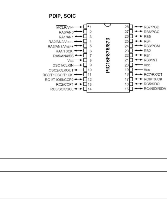
Figure 5.31 shows the pin layout of the chip.
Chapter 5 / The Electronics
81
PDA 05 5/30/03 11:35 AM Page 81
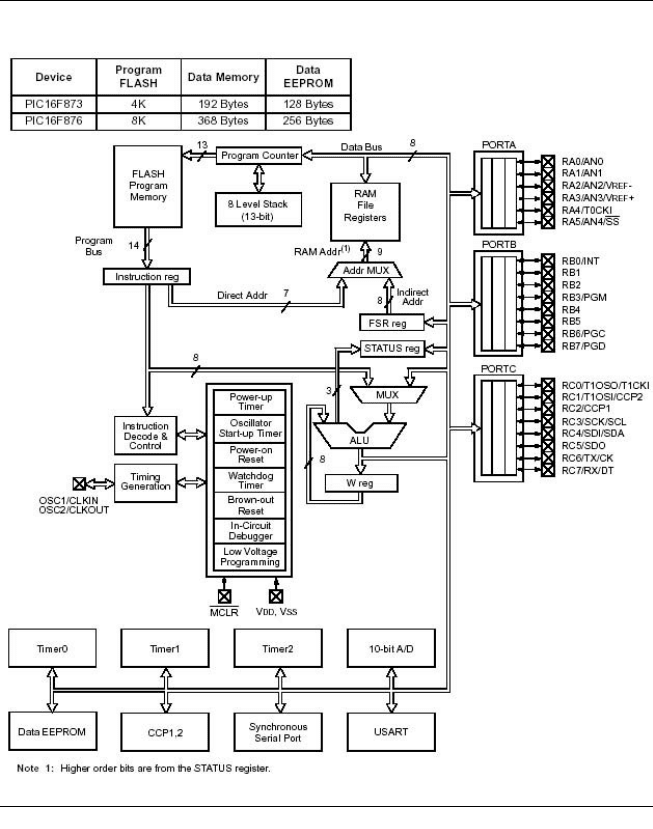
The block diagram in Figure 5.32 gives you an idea of the chip’s inner
architecture.
Table 5.4
PIC16F876 Pin Descriptions
Pin Pin Buffer
Name Pin # Type Type Description
OSC1/CLKIN 9 I ST/ Oscillator crystal input/external clock source
CMOS input.
OSC2/CLKOUT 10 O — Oscillator crystal output. Connects to crystal or
resonator in cr ystal oscillator mode. In RC mode,
OSC2 pin outputs CLKOUT which has 1/4 the
frequency of OSC1, and denotes the instruction
cycle rate.
MCLR/VPP 1 I/P ST Master Clear (Reset) input or programming
voltage input. This pin is an active low RESET to
the device.
PORTA is a bidirectional I/O port.
A0/AN0 2 I/O TTL RA0 can also be analog input0.
RA1/AN1 3 I/O TTL RA1can also be analog input0.
RA2/AN2/ 4 I/O TTL RA2 can also be analog input2 or negative analog
VREF- reference voltage.
RA3/AN3/ 5 I/O TTL RA3 can also be analog input3 or positive analog
VREF+ reference voltage.
RA4/T0CKI 6 I/O TTL RA4 can also be the clock input to the imer0
timer/counter. Output is open drain type.
(continued on page 84)
PDA Robotics
82
Figure 5.31
PIC16F876 pin
layout.
PDA 05 5/30/03 11:35 AM Page 82
Chapter 5 / The Electronics
83
Figure 5.32
PIC16F873 and PIC16F876 block diagram.
PDA 05 5/30/03 11:35 AM Page 83

Table 5.4
PIC16F876 Pin Descriptions (continued)
Pin Pin Buffer
Name Pin # Type Type Description
RA5/SS/AN4 7 I/O TTL RA5 can also be analog input4 or the slave select
for the synchronous serial por t.
PORTB is a bidirectional I/O port. PORTB can be
software programmed for internal weak pull-up on
all inputs.
RB0/INT 21 I/O TTL/ST RB0 can also be the external interrupt pin.
RB1 22 I/O TTL
RB2 23 I/O TTL
RB3/PGM 24 I/O TTL RB3 can also be the low-voltage programming input.
RB4 25 I/O TTL Interrupt-on-change pin.
RB5 26 I/O TTL Interrupt-on-change pin.
RB6/PGC 27 I/O TTL/ST Interrupt-on-change pin or in-circuit debugger pin.
Serial programming clock.
RB7/PGD 28 I/O TTL/ST Interrupt-on-change pin or in-circuit debugger pin.
Serial programming data.
PORTC is a bidirectional I/O port.
RC0/T1OSO/ 11 I/O ST RC0 can also be the Timer1 oscillator output or
T1CKI Timer1 clock input.
RC1/T1OSI/ 12 I/O ST RC1 can also be the Timer1 oscillator input or
CCP2 Capture2 input/Compare2 output/PWM2 output.
RC2/CCP1 13 I/O ST RC2 can also be the Capture1 input/Compare1
output/PWM1 output.
RC3/SCK/SCL 14 I/O ST RC3 can also be the synchronous serial clock
input/output for both SPI and I2C modes.
RC4/SDI/SDA 15 I/O ST RC4 can also be the SPI data in (SPI mode) or
data I/O (I2C mode).
RC5/SDO 16 I/O ST RC5 can also be the SPI data out (SPI mode).
RC6/TX/CK 17 I/O ST RC6 can also be the USART asynchronous
transmit or synchronous clock.
RC7/RX/DT 18 I/O ST RC7 can also be the USART asynchronous
receive or synchronous data.
VSS 8,19 — P Ground reference for logic and I/O pins.
VDD 20 — P Positive supply for logic and I/O pins.
PORTA and the TRISA Register
PORTA is a 6-bit-wide, bidirectional port. The corresponding data
direction register is TRISA. Setting a TRISA bit (= 1) will make the cor-
responding PORTA pin an input (i.e., put the corresponding output
PDA Robotics
84
PDA 05 5/30/03 11:35 AM Page 84
Chapter 5 / The Electronics
85
Data
Bus
WR
Port
WR
TRIS
RD
TRIS
Data Latch
RD Port
DQ
Q
CK
TRIS Latch
DQ
Q
CK
V
DD
VSS
P
N
Analog
Input
Mode
QD
EN
TTL
Input
Buffer
I/O pin
(1)
To A/D Converter
Note 1: I/O pins have protection diodes to VDD and VSS.
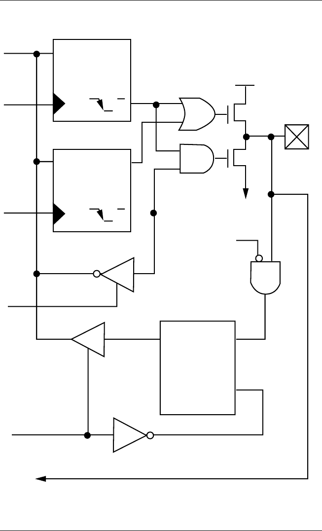
Figure 5.33
Block diagram of RA3:RA0 and RA5 pins.
PDA 05 5/30/03 11:35 AM Page 85
driver in a high-impedance mode). Clearing a TRISA bit (⫽ 0) will
make the corresponding PORTA pin an output (i.e., put the contents
of the output latch on the selected pin).
Reading the PORTA register reads the status of the pins, whereas writ-
ing to it will write to the port latch. All write operations are read-mod-
ify-write operations. Therefore, a write to a port implies that the port
PDA Robotics
86
Data
Bus
WR
Port
WR
TRIS
RD
TRIS
Data Latch
RD Port
DQ
Q
CK
TRIS Latch
V
SS
N
QD
EN
I/O pin
(1)
TMR0 Clock Input
Note 1: I/O pins have protection diodes to VSS only.
DQ
Q
CK
Schmitt
Trigger
Input
Buffer
Figure 5.34
Block diagram of RA4/TOCK1 pin.
PDA 05 5/30/03 11:35 AM Page 86

pins are read, the value is modified, and then written to the port data
latch.
Pin RA4 is multiplexed with the Timer0 module clock input to
become the RA4/T0CKI pin. The RA4/T0CKI pin is a Schmitt Trigger
input and an open drain output. All other PORTA pins have TTL input
levels and full CMOS output drivers. Other PORTA pins are multi-
plexed with analog inputs and analog VREF input. The operation of
each pin is selected by clearing/setting the control bits in the ADCON1
register (A/D Control Register1). Note: I/O pin has protection diodes to
VSS only.
The TRISA register controls the direction of the RA pins, even when
they are being used as analog inputs. The user must ensure the bits in
the TRISA register are maintained set when using them as analog
inputs.
Chapter 7: Programming the PIC16F876 Microcontroller explains how
to set the TRIS registers using a C code macro.
PORTB and the TRISB Register
PORTB is an 8-bit-wide, bidirectional port. The corresponding data
direction register is TRISB. Setting a TRISB bit (= 1) will make the cor-
responding PORTB pin an input (i.e., put the corresponding output
driver in a Hi-Impedance mode). Clearing a TRISB bit (= 0) will make
the corresponding PORTB pin an output (i.e., put the contents of the
output latch on the selected pin).
Three pins of PORTB are multiplexed with the Low Voltage
Programming function: RB3/PGM, RB6/PGC, and RB7/PGD.
Each of the PORTB pins has a weak internal pull-up. A single control
bit can turn on all the pull-ups. This is performed by clearing bit
RBPU (OPTION_REG<7>). The weak pull-up is automatically turned
off when the port pin is configured as an output. The pull-ups are dis-
abled on a Power-on Reset.
Four of the PORTB pins, RB7:RB4, have an interrupt on-change fea-
ture. Only pins configured as inputs can cause this interrupt to occur
(i.e., any RB7:RB4 pin configured as an output is excluded from the
interrupton-change comparison). The input pins (of RB7:RB4) are
compared with the old value latched on the last read of PORTB. The
Chapter 5 / The Electronics
87
PDA 05 5/30/03 11:35 AM Page 87