Douglas H. Williams. PDA Robotics. 2003. 256p
Подождите немного. Документ загружается.


8. 8-pin DIP switch
9. 18-pin DIP IC socket (Note the PIC16F876 is using two—one cut
down)
10. 6-post 2.5 mm DIP headers
11. 20.0000 MHz crystal
12. 11.0592 MHz crystal
13. 1-pin header for analog input
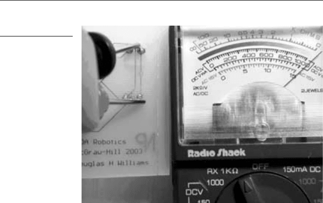
It is good practice to check the conductance after soldering a compo-
nent to the board. This ensures that electricity will flow between the
points on the circuit and with little resistance. If conductivity is poor,
it means that the solder joint is poor and should be redone. To check
for conductivity, set the multimeter to RX 1 KΩ, and touch one probe
on the solder weld and the other on a trace to which it is connected.
PDA Robotics
118
Figure 6.10
Enlarged view of left side of main board.
PDA 06 5/27/03 8:37 AM Page 118

The needle on the meter should “spike” to the right, showing zero
resistance. Figure 6.12 shows the meter set to RX 1 KΩ, with the leads
crossed and the needle to the far right, indicating that there is no
resistance and that the meter is working properly. Figure 6.13 shows
testing the conductivity of the solder connections.
Chapter 6 / Building PDA Robot
119
Figure 6.11
Enlarged view of
right side of main
board.
Figure 6.12
Setting the meter
for conductivity
testing.
PDA 06 5/27/03 8:37 AM Page 119
To ensure a good solder joint, keep the tip of the iron clean. Buy high-
quality fairly thin solder, and ensure that the iron is hot. Clean the tip
after soldering two or three joints.
Placing and Soldering the
Motor Controller Components
Figures 6.14 to 6.16 show the placement of the parts on the motor con-
troller circuit. The following numbers correspond to those on the
motor controller circuit board. Ensure that the diodes are oriented cor-
rectly, as shown in the figure.
1. Molex 3.9 mm 2P headers with ramp connects to Molex .156"
wire connectors
2. .1 UF capacitors (or higher)
3. 4007 746 diodes
4. 6-post 2.5 mm DIP headers
5. L298N dual bridge driver
PDA Robotics
120
Figure 6.13
Testing the solder
connections on a
prototype circuit.
PDA 06 5/27/03 8:37 AM Page 120

Chapter 6 / Building PDA Robot
121
Figure 6.14
Parts placement on the motor controller circuit board.
Figure 6.15
Close-up of left side
of the motor
controller.
PDA 06 5/27/03 8:37 AM Page 121

The Infrared Transceiver
Solder the 6-post 2.5 mm DIP header to the board normally, with the
long pins on the top of the board. Position the TFDS4500 on the pads
on the bottom of the board, ensuring that the middle of the transceiv-
er is centered over the middle of the pads. Solder or epoxy the pins to
the pads being careful to not short any of the pads. Ensure that you are
using a good conductive epoxy. Figure 6.17 shows the TFDS4500
lined up and ready for the epoxy or solder to be applied. Note: If using
PDA Robotics
122
Figure 6.16
Close-up of right
side of the motor
controller.
Figure 6.17
Close-up of the
TFDS4500 ready to
be soldered or
epoxyed to the
board.
PDA 06 5/27/03 8:37 AM Page 122
epoxy, gently scrape off the photoresist (which protects the pads from
corrosion) in order to achieve a good contact. A small flathead screw-
driver works well for this. Once the solder or epoxy has set, it is a good
idea to cement the backside of the transceiver with a regular noncon-
ducting epoxy.
Set the boards aside until ready to drill the mounting holes. I recom-
mend putting them in a static-proof bag. We will mount the boards to
the craft once the other steps, such as creating the ribbon cables and
drilling the holes in the support pieces, etc., are done.
The Power Connectors
The Battery Packs
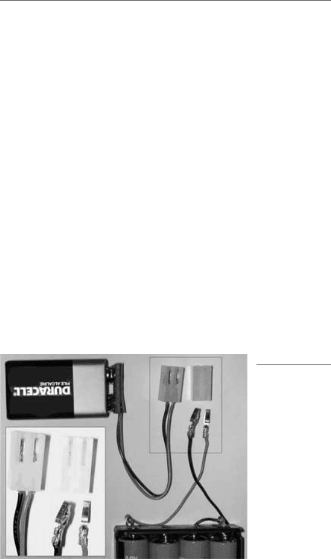
To prepare the power connectors for the battery packs, motors, and the
IR range finder, you will need to solder the Molex .156" (3.9 mm) wire
connectors and slide them into the plastic moldings provided. Figure
6.18 shows the connectors of the battery packs. Note: the ground wire
is always inserted on the left side of the connector. You may want to
solder on/off switches between one of the leads. I simply plug and
unplug the power connectors to the posts to turn the craft on or off.
Chapter 6 / Building PDA Robot
123
Figure 6.18
The power
connections.
PDA 06 5/27/03 8:37 AM Page 123

The IR Range Finder
The connector that comes with the Sharp GP2D12 needs to have the
power leads connected to the 3.9 mm Molex wire connector as well.
Solder the black and red wires to the inserts the same way as the
battery leads, with the ground wire on the left. The blue wire on the
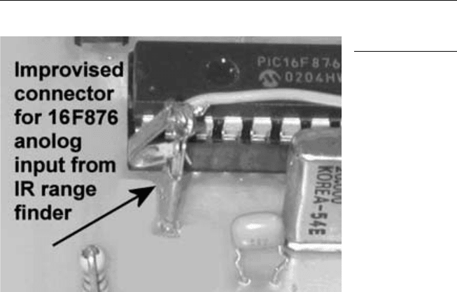
connector goes to the analog input. I improvised a connector for the
solitary analog input pin of the PIC16F876 by using a 3.9 mm connec-
tor turned around with the end that normally has the wire soldered to
it, crimped to fit the pin. This works well because the connector is
secured to the pin by the flexible metal tab. Figure 6.19 shows the sol-
dered connections.
Figure 6.20 shows the improvised connector snug on the PIC16F876
analog input pin.
The two motors will also need to have the Molex power connectors
fastened. But first, we must assemble the gear boxes and drill the holes
that the wires will feed though from the bottom of the PDA Robot.
PDA Robotics
124
Figure 6.19
The IR range finder
connections. A:
Positive (red), B:
Ground (black), C:
Analog line (blue).
PDA 06 5/27/03 8:37 AM Page 124
Cutting the Aluminum Pieces
and Drilling the Holes
Cut the bottom plate (main platform) into an 8" ⫻ 6" piece. Cut the top
plate that is suspended on four hex spacers to 7" and 5-1/4". Drill out
the holes, as outlined in Figures 6.21 and 6.22.
• Aluminum: 8" ⫻ 6" ⫻ 1/16" (main platform)
• Aluminum: 7" ⫻ 5-1/4" (top platform) ⫻ 1/16"
• Aluminum: 1" ⫻ 1/2" ⫻ 1/4" (accessory mount)
• Two Tamiya six-speed geared motors (www.hvwtech.com)
• Three Tamiya wheel sets
• Four 1" L-brackets
Mount the hex brackets on the top of the platform. Mount the motors,
wheel brackets, and range finder on the bottom. Figure 6.23 shows the
underside with the motors and wheels mounted to the platform. The
2" hex spacers secure the outside bolts used to mount the motors.
Ensure that both motors are oriented in the same direction. If they
aren’t, the PDA control software will have to be modified to control
the direction of PDA Robot’s motion. Figure 6.23 shows the underside
of the main platform with the motors, range finder, and wheels mount-
ed. The two pieces of balsa wood under the motor gearboxes raise the
Chapter 6 / Building PDA Robot
125
Figure 6.20
The IR analog input
connector.
PDA 06 5/27/03 8:37 AM Page 125

PDA Robotics
126
Figure 6.21
Main platform drill
diagram.
Figure 6.22
Drilled out platform
showing par ts
placement.
PDA 06 5/27/03 8:37 AM Page 126

motors so that they are higher than the outer wheels. This ensures
good traction so PDA Robot can turn easily.
Assembling the Geared Motors
I chose the Tamiya six-speed gearbox for this project and set the gear
ratio to 76.5:1. This gives the craft enough power to move over dense
carpet at a reasonable speed without stalling. The gear kit comes with
detailed instructions on assembling the motors. Figure 6.24 shows the
step in the assembly instructions detailing the gear placement for the
76.5:1 ratio (132-rpm). Figure 6.25 shows the assembled gearbox.
To mount the wheels on the gearboxes, insert the spring pin and use
wheel hub #2 provided with the sports tire set, and fasten the wheel
to the shaft using the hex wrench that comes with the kit. Figure 6.26
shows how to mount the wheel hub on the shaft. Figure 6.27 shows
the mounted gearbox with the wheel attached.
Chapter 6 / Building PDA Robot
127
Figure 6.23
Underside of the
main platform.
PDA 06 5/27/03 8:37 AM Page 127