Fieldbus Foundation. System Engineering Guidelines
Подождите немного. Документ загружается.

Revision 3.1 - 120 - March 2010
Junction Box
+
-
Transmitter
+
-
SG
+
-
SG
+
-
SG
+-
FF Host
Interface
FF PWR
Supply
24 vdc
GND Reference
Host Enclosure
Process Tank
Pump
Structural Steel
Structural Steel
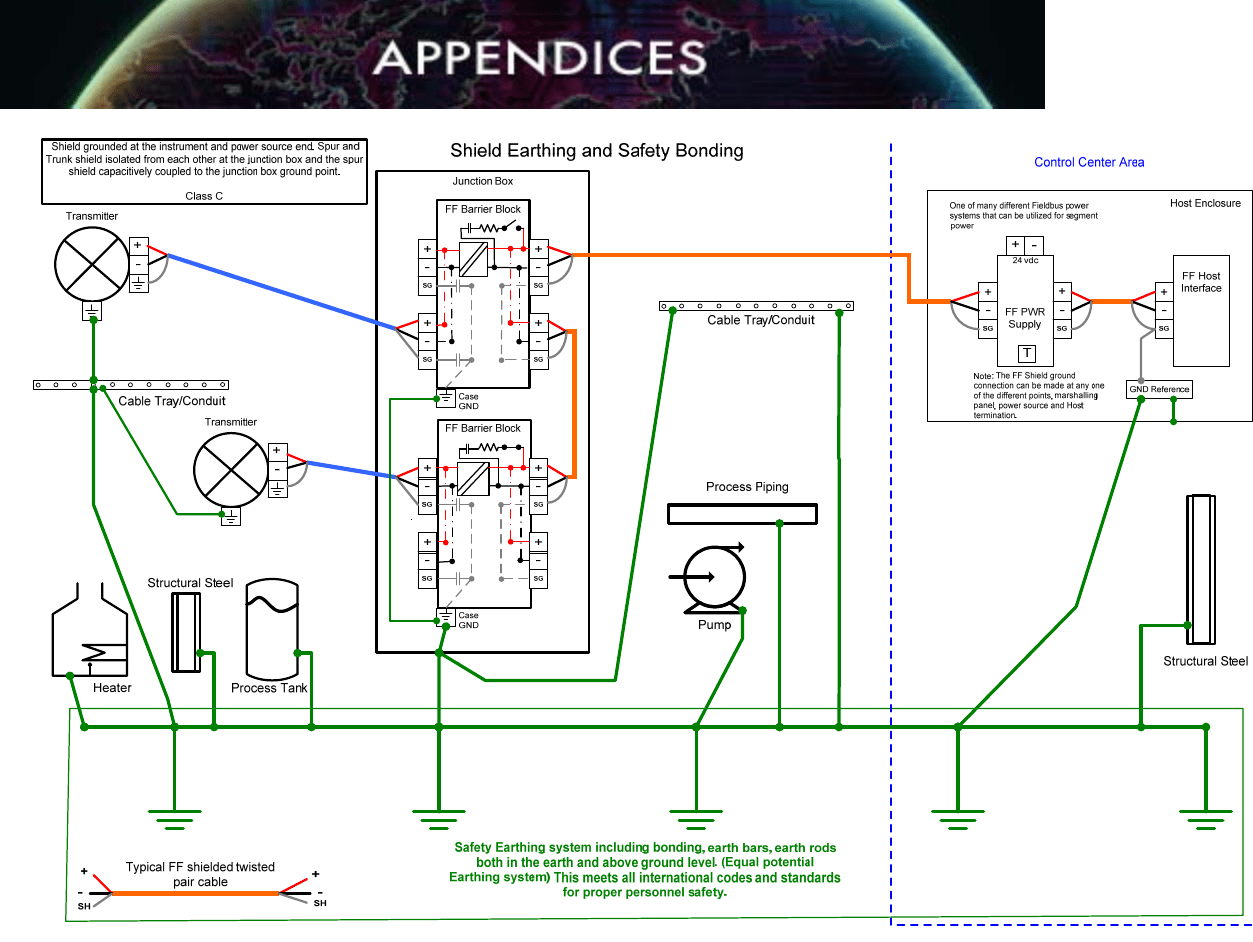
Safety Earthing system including bonding, earth bars, earth rods
both in the earth and above ground level. (Equal potential
Earthing system) This meets all international codes and standards
for proper personnel safety.
Cable Tray/Conduit
Cable Tray/Conduit
Heater
Process Piping
T
Control Center Area
Average Distance 300
meters or less
Average Distance
50 meters
Shield Earthing and Safety Bonding
+
-
SG
+
-
SG
+
-
SG
+
-
SG
FF Terminal Block
Case
GND
+
-
SG
+
-
SG
+
-
SG
+
-
SG
FF Terminal Block
Case
GND
+
-
Transmitter
Typical FF shielded twisted
pair cable
+
+
--
SH
SH
One of many different Fieldbus power
systems that can be utilized for segment
power
Note: The FF Shield ground
connection can be made at any one
of the different points, marshalling
panel, power source and Host
termination.
Multi-Point Shield grounding at the
instrument and power source ends.
Class B
Figure 7-7. Class B: Multi-point Shielding.
Revision 3.1 - 121 - March 2010
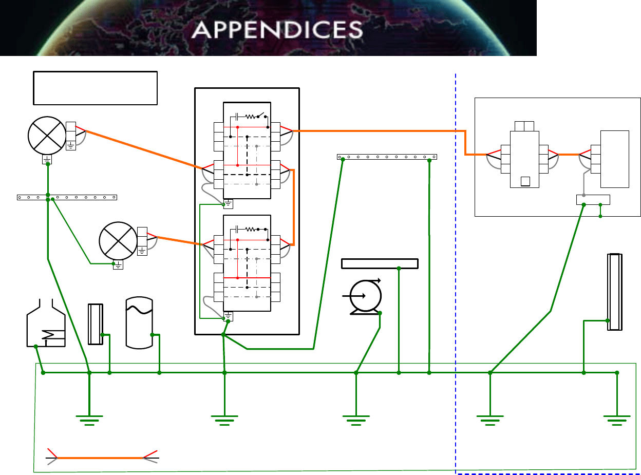
Figure 7-8. Class C: Shielding Using Isolating Device Couplers.
Revision 3.1 - 122 - March 2010
Junction Box
+
-
Transmitter
+
-
SG
+
-
SG
+
-
SG
+-
FF Host
Interface
FF IS PWR
Supply
24 vdc
GND Reference
Host Enclosure
Process Tank
Pump
Structural Steel
Structural Steel
Safety Earthing system including bonding, earth bars, earth rods
both in the earth and above ground level. (Equal potential
Earthing system) This meets all international codes and standards
for proper personnel safety.
Cable Tray/Conduit
Cable Tray/Conduit
Heater
Process Piping
T
Control Center Area
Average Distance 500
meters
Average Distance
50 meters
Shield Earthing and Safety Bonding
+
-
SG
+
-
SG
+
-
SG
+
-
SG
FF Terminal Block
Case
GND
+
-
SG
+
-
SG
+
-
SG
+
-
SG
FF Terminal Block
Case
GND
+
-
Transmitter
Typical FF shielded twisted
pair cable
+
+
--
SH
SH
One of many different Fieldbus power
systems that can be utilized for segment
power
Note: The FF Shield ground
connection can be made at any one
of the different points, marshalling
panel, power source and Host
termination.
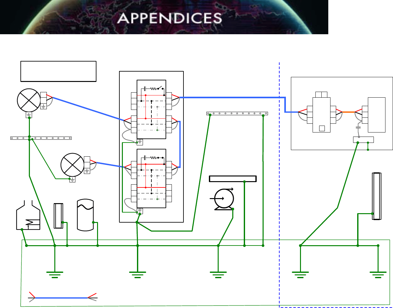
Shield grounded at the instrument end and
capacitively coupled at the power source end.
Class D
Figure 7-9. Class D: Multi-point Shielding Using Capacitive Coupling.

Revision 3.1 - 123 - March 2010
APPENDIX 4: RISK MANAGEMENT
The following valve process effect rating and network/segment loading method should
be used as a guide and modified to suit the individual process facility. The valve and
associated measurement process effect shall be defined for prudent loading of Fieldbus
segments. The following ratings should be assigned to each valve and segment.
Commentary:
The design restrictions are intended to minimize the effect of human error and
interoperability problems from affecting plant reliability. The intent of High Process
Effect designs is to keep the number and variety of devices on a network small so that a
minimum of interaction is required with the segment. Less is better; however, a unit with
large numbers of dependent service valves may decide to increase the maximum
number of valves to three (3) for High Process Effect.
Instruments that are part of a common reliability concept should not be on the same
network (share the same Host I/O controller) and, if possible, backplane to minimize the
number of possible common mode failure points.
A4.1 Process Effect Ranking HIGH Criteria
• Causes a system trip, which shuts down entire operating process or train
or no production for more than one (1) 8-hour shift.
• And no operator action and time available to mitigate process (entire) or
train shutdown.
A4.2 Process Effect Ranking MEDIUM Criteria
• Causes a system trip, which shuts down entire operating process or train
but production can be resumed on the same 8-hour shift
• Or production will be reduced to lower rates.
• In this case, the process dynamics will allow the operator enough time to
mitigate the problem. Final control element can be operated manually and
can be back online shortly without process shutdown.
A4.3 Process Effect Ranking LOW Criteria
• Will not cause short-term risk of a system trip and will not shutdown the
entire operating process or train
• Final control element can be in a fail position for a short time without
immediate operator action.

Revision 3.1 - 124 - March 2010
Table A4.1. Process Effect Ranking Matrix
FAILURE
MITIGATIONS
LEVEL 1 LEVEL 2 LEVEL 3 LEVEL 4
PROCESS
EFFECT
CATEGORY ▼
NO OPERATOR
ACTION OR TIME
AVAILABLE TO
MITIGATE UNIT
OR TRAIN
SHUTDOWN
WHEN CONTROL
LOOP FAILS
LIMITED
OPERATOR
ACTION AND
IMMEDIATE TIME
TO MITIGATE UNIT
OR TRAIN
SHUTDOWN
WHEN CONTROL
LOOP FAILS
AVAILABLE
OPERATOR
ACTIONS AND
LIMITED TIME TO
MITIGATE UNIT
OR TRAIN
SHUTDOWN
WHEN CONTROL
LOOP FAILS
AVAILABLE
OPERATOR
ACTIONS AND
EXTENDED TIME
TO MITIGATE UNIT
OR TRAIN
SHUTDOWN
WHEN CONTROL
LOOP FAILS
1. UNIT or TRAIN
SHUTDOWN
No production for
more than one (1)
8-hour shift.
HIGH
MEDIUM
MEDIUM
LOW
2. UNIT or TRAIN
CONTINUES
TO OPERATE
Production can be
resumed on the
same shift.
MEDIUM
MEDIUM LOW LOW
3. UNIT or TRAIN
CONTINUES
TO OPERATE
Production will be
reduced to lower
rates.
MEDIUM
LOW
LOW
LOW
4. UNIT or TRAIN
CONTINUES
TO OPERATE
Insignificant impact
to production or
quality.
LOW
LOW
LOW
LOW

Revision 3.1 - 125 - March 2010
Risk Management Selections
Redundant Controller Required
Redundant H1 Interface Optional
Redundant Power Supplies Required
DC Power Supply Battery Capacity Required - 30 minutes minimum
Redundant Power Conditioners
(Fieldbus Power Supplies)
Required
Field Backup LAS
Only if a redundant H1 interface is not
provided and high reliability is necessary
Control in Valve Positioner Preferred for simple loops
Control in Transmitter Only for Cascade Primary
Control in Host Required for Complex Loops
Valve / Segment Process Effect
Ranking
Required
Maximum Devices per Segment
12 (default unless otherwise noted in
section 7.4 or 7.7)
Maximum Control Valves per Segment
3 (default unless otherwise noted in
section 7.4 or 7.7)
Repeaters Requires Project Lead Engineer approval
Table A4.2. Network/Segment Risk Management Selections

Revision 3.1 - 126 - March 2010
APPENDIX 5: FIELDBUS SEGMENT TESTING
DOCUMENTATION
A5.1 Fieldbus Segment Commissioning Form
Table A5.1. F
OUNDATION fieldbus segment commissioning form for non-isolated coupler
or trunks only on segments with isolated couplers (for spurs on segments with isolated
couplers repeat test for each spur).
Company:
__________________________________________________
Location:
__________________________________________________
Unit:
__________________________________________________
Segment No.:
__________________________________________________
Date
Step 1: This testing is performed before the segment is plugged into the power
conditioner.
(+) to (-) Expected > 50K ohm Actual = _______________
(+) to shield Expected > 20M ohm Actual = _______________
(-) to shield Expected > 20M ohm Actual = _______________
(+) to ground Expected > 20M ohm Actual = _______________
(-) to ground Expected > 20M ohm Actual = _______________
shield to ground Expected > 20M ohm Actual = _______________
Step 2: Plug the segment into the power conditioner.
Shield to ground Expected < 1 ohm Actual = _______________
Step 3: Clip a FBT-6 or P&F tester onto the segment and capture the segment
diagnostics file.
Segment Diagnostics File: __________________________________________________
Date: __________________________________________________
Technician:
__________________________________________________
Step 4: Optionally capture a segment trace file with an oscilloscope.
Segment Trace File: __________________________________________________
Date: __________________________________________________
Technician:
__________________________________________________
Revision 3.1 - 127 - March 2010
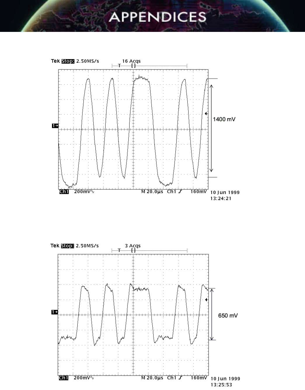
A5.2 Sample Waveforms
Measure the AC waveform at the marshaling cabinet terminal block field connector.
Procedure
Expected Result
Set the scope to AC, 200 mV/division,
10 microseconds/division for best
results and press HOLD to capture the
waveform.
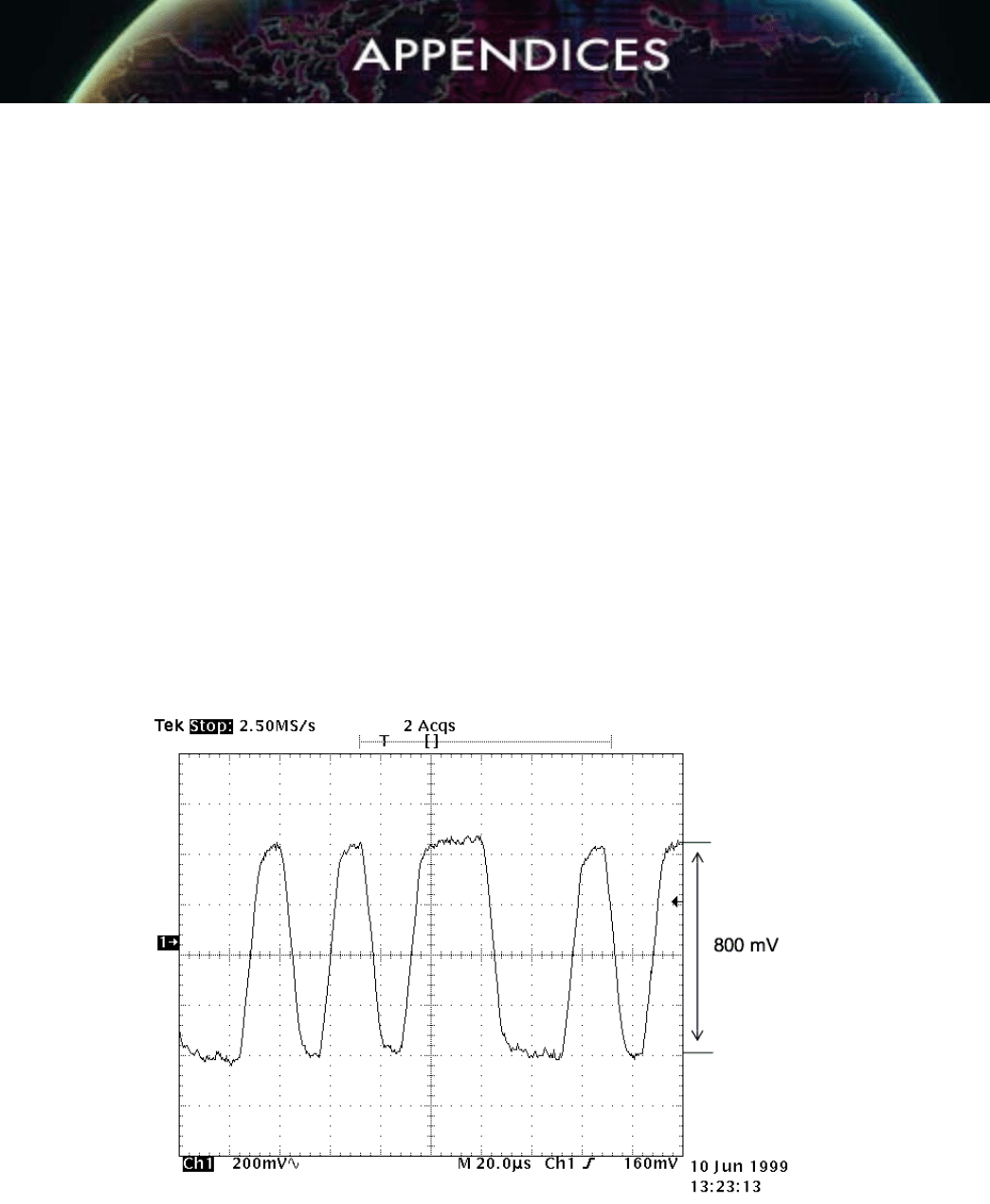
350 mV and 700 mV peak to peak
Verify the waveform against the expected waveform shown in Waveform with Two Terminators
and 1,000 ft. Cable (Figure A5.1). Note the differences in the signals with one terminator
(Waveform with One Terminator and 1,000 ft. Cable) and with three terminators (Waveform
with Three Terminators and 1,000 ft. Cable).
The following figure (A5.1) shows a waveform with two terminators and 1,000 ft. of cable. This
is the expected waveform.
Figure A5.1. Waveform with Two Terminators and 1,000 ft. Cable.
Revision 3.1 - 128 - March 2010
The following figure (A5.2) shows a waveform with one terminator and 1,000 ft. of cable.
Figure A5.2. Waveform with one Terminator and 1,000 ft. Cable.
The following figure (A5.3) shows a waveform with three terminators and 1,000 ft. of cable.
Figure A5.3. Waveform with Three Terminators and 1,000 ft. Cable.

Revision 3.1 - 129 - March 2010
APPENDIX 6: F
OUNDATION FIELDBUS SEGMENT AND LOOP
DRAWINGS
Four drawings are provided illustrating both FOUNDATION fieldbus segment drawings
and instrument loop drawings using two different technologies. The first two drawings
are based upon "brick" style field connectors and assume a significant distance
between the device couplers. This layout should not be used for device couplers inside
the same junction box. In that case, the trunk line will be connected directly to the
individual device couplers.
A segment drawing (Figure A6.1) illustrates how all the devices on one segment are
connected back to the H1 interface on the host system. Figure A64.1 shows six (6)
FOUNDATION fieldbus devices that are connected onto one H1 segment.
An instrument loop drawing (Figure A6.2) illustrates all the devices associated with the
implementation of one control loop. In this case, the control loop comprises a fieldbus
transmitter (flow) and a 4-20 mA level transmitter connected to a 4-20 mA control valve.
In this instance, the loop drawing combines both current (4-20 mA) and digital
(FOUNDATION fieldbus) technologies onto one drawing.
The third drawing (Figure A6.3) is another example of a segment drawing using terminal
blocks in the field junction box (versus a "brick" style connector). In this segment
drawing, four (4) FOUNDATION field devices are connected onto one segment.
The fourth drawing (Figure A6.4) is another example of an instrument loop drawing.
This time, the level transmitter and the level control valve are implemented via
F
OUNDATION fieldbus, whereas the flow transmitter is implemented via 4-20 mA. Again,
terminal blocks are used in the H1 segment implementation consistent with the
associated segment drawing (Figure A6.3).
All drawings are output from SmartPlant Instrumentation (SPI) (previously known as
INtools) using the Enhanced SmartLoop (ESL) functionality of the wiring module.
Project specific drawings may be slightly different, depending on specific project
decisions on the representation of field devices, terminal blocks, wiring colors and field
junction boxes. However, the basic layout will be similar, given the ESL output limits.