Gao R.X., Yan R. Wavelets: Theory and Applications for Manufacturing
Подождите немного. Документ загружается.

the localized defect, the “transient” feature will reoccur at a fundamental frequency
f
0
, which is a function of the bearing rotational speed. Such a relationship will be
reflected in a wavelet transform of the bearing vibration signal, in that the measure
function C(s
1
, m) will retain the same fundamental frequency along the time axis, at
one of its scales (s
1
). As a result, the spectral feature of the transient signal is
retained in the wavelet transform, although it is not explicitly expressed. Because of
masking by noise and other sign als with similar spectral characteristics that appear
at the same scale, it can be difficult to rely on wavelet transform alone to identify
such hidden patterns.
Such constraint of the wavelet transform can be compensated for by subse-
quently applying the Fourier transform to the measure function C(s
1
, m) resulting
from the wavelet transform. Such a postspectral technique reveals the specific
frequency location of the transient features, and presents a unifie d approach to
transient signal processing. The following section explains how such a postspectral
method is realized.
7.2.1 Fourier Transform of the Measure Function
In a complete linear signal space, the wavelet- extracted data set at scale s can be
expressed as:
x
s
ðtÞ¼
Z
u¼1
u¼ 1
C
s
ðuÞW
s
ðt uÞdu ¼ C
s
ðtÞW
s
ðtÞ (7.18)
where the sym bol
N
represents the convolution operation between the measured
function C
s
(u) and the wavelet function W
s
(u). To perform Fourier transform on the
data set, the Fourier transform of the measure function C
s
(u) is first derived. For this
purpose, the wavelet transform defined in (7.15) at a fixed scale s is rewritten as:
C
s
ðuÞ¼
Z
1
1
xðtÞW
s
ðt uÞdt (7.19)
In (7.19), the terms C
s
(u) and W
s
(t u) represent their respective counterparts in
(7.15), C(s, u) and W
s,u
(t), with a fixed scale s. Through a normalization operation,
‖W
1,0
(t)‖
2
in (7.2) is set as 1 for simplicity. With respect to time u, the Fourier
transform of C
s
(u), denoted as
~
C
s
ðf Þ , is derived as:
~
C
s
ðf Þ¼
~
xðf Þ
~
W
s;u
ðf Þ (7.20)
where the sym bol
~
xðf Þ expresses the Fourier transform of the signal x(t). The
symbol
~
W
s;u
ðf Þ expresses the Fourier transform of the wavelet function W
s,u
(t),
which is derived as:
110 7 Wavelet Integrated with Fourier Transform: A Unified Technique

~
W
s;u
ðf Þ¼
Z
1
1
W
s;u
ðtÞe
j2pft
dt ¼
Z
1
1
1
s
p
W
1;0
t u
s
e
j2pft
dt
¼
1
s
p
Z
1
1
W
1;0
t u
s
e
j2pft
s d
t u
s
hi
¼ s
p
Z
1
1
W
1;0
t u
s
e
j2pfs
t u
s
þ
u
s
ðÞ
d
t u
s
¼ s
p
e
j2pfu
Z
1
1
W
1;0
t u
s
e
j2pfs
t u
s
ðÞ
d
t u
s
¼ s
p
e
j2pfu
~
W
1;0
ðsf Þ
(7.21)
Combining (7.21) with (7.20) yields:
~
C
s
ðf Þ¼
~
xðf Þ s
p
e
j2pfu
~
W
1;0
ðsf Þ (7.22)
Let
~
W
1;0
ðsf Þ¼e
j2pfu
~
W
1;0
ðsf Þ,(7.22) can be further expressed as:
~
C
s
ðf Þ¼ s
p
~
xðf Þ
~
W
1;0
ðsf Þ (7.23)
where the superscript * denotes the conjugate operator.
Similar to (7.19), in the case of discrete wavelet transform, the discrete measure
function C
k
(m) at a fixed scale k can be expressed as:
C
k
ðmÞ¼
Z
1
1
xðtÞW
k
ðt mkLÞdt (7.24)
The corresponding Fourier transform of C
k
(m) is expressed as:
~
C
k
ðf Þ¼
~
xðf Þ
~
W
k;m
ðf Þ (7.25)
In (7.25),
~
W
k;m
ðf Þ is derived as follows:
~
W
k;m
ðf Þ¼
Z
1
1
W
k;m
ðtÞe
j2pft
dt ¼
Z
1
1
1
k
p
W
1;0
t mkL
k
e
j2pft
dt
¼
1
k
p
Z
1
1
W
1;0
t mkL
k
e
j2pft
k d
t mkL
k
¼ k
p
Z
1
1
W
1;0
t
k
mL
e
j2pf
t
k
mLþmL
ðÞ
k
d
t
k
mL
¼ k
p
e
j2pfmkL
Z
1
1
W
1;0
t
k
mL
e
j2pfk
t
k
mL
ðÞ
d
t
k
mL
¼ k
p
e
j2pfmkL
Z
1
1
W
1;0
t
k
mL
e
j2pfk
t
k
mL
ðÞ
d
t
k
mL
¼ k
p
e
j2pfmkL
~
W
1;0
ðkf Þ
(7.26)
7.2 Wavelet Transform with Spectral Postprocessing 111
As a result, (7.25) is given by:
~
C
k
ðf Þ¼
~
xðf Þ
~
W
k;m
ðf Þ¼
~
xðf Þ k
p
e
j2pfmkL
~
W
1;0
ðkf Þ (7.27)
Let
~
W
1;0
ðkf Þ¼
~
W
1;0
ðkf Þe
j2pfmkL
,(7.27) can be further expressed as:
~
C
k
ðf Þ¼ k
p
~
xðf Þ
~
W
1;0
ðkf Þ (7.28)
Equations (7.23) and (7.28) illustrate that the Fourier transform of the measure
function at scale s (for continuous tra nsform) or k (for discrete transform) can be
viewed as the original signal x(t) passing through a data filter, which is a contracted
(by a frequency factor of s or k) and amplified (by a factor of s
p
or k
p
) version of
the filter represented by the base wavelet function. Such an operation establishes the
link between measured function and data filtering, and is of significance in wavelet
transform-based signal analysis.
7.2.2 Fourier Transform of Wavelet-Extracted Data Set
With the Fourier transform of the measure function obtained, the Fourier transform
of the extracted (or reconstructed) data set from the continuous wavelet transform,
denoted x
s
(t) as shown in (7.18), can be derived as:
~
x
s
ðf Þ¼
~
C
s
ðf Þ
~
W
s
ðf Þ
¼ s
p
~
xðf Þ
~
W
1;0
ðsf Þ s
p
~
W
1;0
ðsf Þ
¼s
~
xðf Þj
~
W
1;0
ðsf Þj
2
(7.29)
In case of a discrete wavelet transform, the Fourier transform of the data set x
k
(t)is
obtained by setting s ¼ k and u ¼ mkL in (7.18), and its Fourier transform is
expressed as:
~
x
k
ðf Þ¼
~
C
k
ðf Þ
~
W
k
ðf Þ
¼ k
p
~
xðf Þ
~
W
1;0
ðkf Þ k
p
~
W
1;0
ðkf Þ
¼k
~
xðf Þj
~
W
1;0
ðkf Þj
2
(7.30)
This indicates that the Fourier transform of the extracted data set x
k
(t) at scale k can
be viewed as the Fourier transform of the original signal x(t) passing through a low-
pass filter and the filter being represented by the transfer function j
~
W
1;0
ðkf Þj
2
. If the
template function at scale k correlates well with the “transient” feature of the signal
x(t) in the time domain, then its Fourier transform will contain a strong “distur-
bance” component in its spectrum. As a result, the filter j
~
W
1;0
ðkf Þj
2
will extract the
112 7 Wavelet Integrated with Fourier Transform: A Unified Technique
“disturbance” signal features from the original signal x(t) at the scale k, as shown in
(7.29) and (7.30). Because of a lower degree of correlation between this filter and
other constituent components in the signal, othe r components will be attenuated at
the scale k.
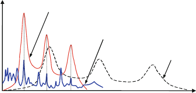
The filtering effect of postspectral processing of a wavelet transformed data
series is illustrated in Fig. 7.3 . The “transient” feature, represented by the solid thick
line, is shown to have a fundamental frequency f
1
, characterized by a magnitude
peak at f
1
and its harmonics (2f
1
and 3f
1
) in the frequency spectrum. When an
appropriate base wavelet is selected (or designed) to decompose this signal (Holm-
Hansen et al. 2004), a base template function will exist at a certain scale k where a
high degree of correlation between the template function and the “transient”
features can be identified. If the data set resulting from such a wavelet transform
is subsequently processed by the Fourier transform, the result will be a data
spectrum similar to that of the “transient” signal, with its major frequency compo-
nents at f
1
,2f
1
, and 3f
1
, respectively. Such a postspectral analysis can be viewed as
filtering the data set in the frequency domain denoted by
~
W
1;0
ðkf Þ.
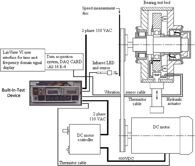
7.3 Application to Bearing Defect Diagnosis
This section illustrates how the unified time scale frequency analysis technique
described earlier can be applied to rolling bearing defect diagnosis. A custom-
designed bearing test bed, as shown in Fig. 7.4, is set up to provide an experimental
platform for evaluating the developed method. Axial and radial loads on the test
bearing are applied through a hydraulic system, and the bearing rotation speed is
varied by controlling the DC drive motor. Commercially available accelerometers
(model 8624) are placed on the housing for vibration measurement with a data
sampling frequency of 10 kHz. A deep-groove ball bearing of type 6220 with a
seeded structural defect serves as the test bearing. The defect is implemented as a
0.25-mm diameter hole drilled on the inner raceway of the bearing, simulating the
Frequency
Magnitude
W
1,0
( f )
f
1
f
1
2f
1
3f
Disturbance
Feature
Base Template
Function
x( f )
Wavelet
Filter
W
1,0
(kf )
~
~
~
Fig. 7.3 Illustration of the filtering effect of wavelet transform
7.3 Application to Bearing Defect Diagnosis 113
condition of a surface spal l. The relationship between the bearing rotational
frequency f
r
and the characterist ic frequencies associa ted with defect-induced
vibrations can be determined analytically as a function of the defect location, for
example, on the inner raceway (f
BPFI
), outer raceway (f
BPFO
) or a rolling element
(f
BSF
) (Harris 1991). Specifically for the test bearing, these characteristic frequen-
cies are calculated as f
BPFI
5.86f
r
, f
BPFO
4.1f
r
, f
BSF
5.3f
r
, respectively (SKF
1996). By identifying the existence of these characteristic frequencies and/or their
combinations, the existence of bearing structural defects can be determined.
In the experimental evaluation, following aspects are studied:
1. The effectiveness of the unified time scale frequency analysis technique in
extracting defect features (i.e., characteristic frequencies) from bearing vibration
signals is compared to that of the Fourier transform and the discrete wavelet
transform when it is applied alone.
2. The effectiveness of the new technique at different wavelet decomposition
levels.
3. The effectiveness of the new technique under varying bearing operating condi-
tions, such as the radial load, axial load, and shaft rotational speed.
Fig. 7.4 Bearing test bed with hydraulic load application capability
114 7 Wavelet Integrated with Fourier Transform: A Unified Technique
7.3.1 Effectiveness in Defect Feature Extraction
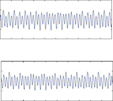
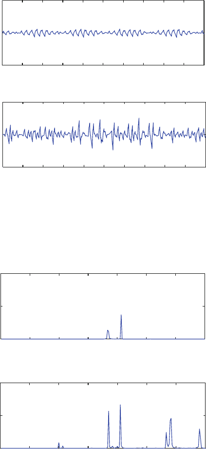
To establish a basis for objective comparison, vibration signals are measured on both
a defect-free (i.e., healthy) and a defective bearing of the same model (SKF 6220),
under the same operation conditions: shaft speed f
r
¼ 600 rpm (corresponding to 10
Hz rotational frequency), axial load of 7,038 N, and radial load of 17,468 N.
Figures 7.5 and 7.6 shows the two signals in the time and frequency domains,
respectively, while the related frequency resolution is approximately 0.3 Hz.
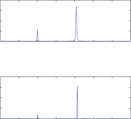
As shown in Fig. 7.6, both spectra indicate the existe nce of two dominant
frequency com ponents: (1) ball rotation (f
BPFO1
, ball passing frequency on outer
raceway, with the subscript “1” referring to the 6220 bearing) and (2) bearing
misalignment (f
m
). Ball rotation-related vibration has a peak value at the funda-
mental frequency f
BPFO1
¼ 41 Hz, which is equal to 4.1 f
r
. Misalignm ent-related
vibration has a characteristic frequency of f
m
¼ 20 Hz ( ¼ 2f
r
). In addition to these
two major com ponents, components related to bearing imbalance are also identified
at the frequency f
u
¼ 10 Hz (identical to f
r
). However, visual comparison of the
two spectra reveals no difference between them, as the characteristic frequency
of f
BPFI1
¼ 58.6 Hz, related to the inner raceway defect, is not recognized.
0 0.1 0.2 0.3 0.4 0.5 0.6 0.7 0.8 0.9 1
−1
−0.5
0
0.5
1
Time (s)
Signal (V)
Signals from a healthy bearing
0 0.1 0.2 0.3 0.4 0.5 0.6 0.7 0.8 0.9 1
−1
−0.5
0
0.5
1
Time (s)
Signal (V)
a
b
Signals from a defective bearing
Fig. 7.5 Time domain signals from a healthy and a defective bearing. (a) Signals from a healthy
bearing and (b) signals from a defective bearing
7.3 Application to Bearing Defect Diagnosis 115
This illustrates that Fourier transform, when applied alone, may not be effective in
detecting the existence of bearing structural defect.
The same signals are then analyzed using discrete wavelet transform, with the
Daubechies 2 wavelet as the base wavelet. Figure 7.7 illustrates the wavelet
coefficients of the vibration signals at the decomposition level 7, which has a
corresponding frequency range of 39 78 Hz, thus covering the defect characterist ic
frequency of f
BPFI1
¼ 58.6 Hz. As seen in Fig. 7.7 , the wavelet coefficients for the
defective bearing have shown more dynamical variations than that of the healthy
bearing. To quantify their difference, the root-mean-square (RMS) values of the
two wavelet coefficients are calculated. It is found that the RMS value of the
defective bearing (56 mV) is about 145% larger than that of the healthy bearing
(22.8 mV). Although such an increase can be used as an indicator of structure defect
in the bearing, it has the limitation that proper threshold needs to be set up a priori,
to determine the quantitative extent that distinguishes a healthy bearing from a
defective one. Another limitation of the wavelet transform is that the wavelet
coefficients do not provide any indication on the specific location of the defect in
the bearing, since it does not explicitly reveal the characteristic frequencies from
the bearing.
Next, the bearing signal (as shown in Fig. 7.5) is analyzed using the unified
time scale frequency method. For this purpose, the wavelet coefficients of the
signal (shown in Fig. 7.7) is postprocessed using the Fourier transform.
0 10 20 30 40 50 60 70
0
0.01
0.02
0.03
0.04
Frequency (Hz)
PSD (Watts/Hz)
f
m
f
u
Power spectrum density from a healthy bearing
0 10 20 30 40 50 60 70
0
0.02
0.04
0.06
0.08
Frequency (Hz)
PSD (Watts/Hz)
f
m
f
u
Power s
p
ectrum densit
y
from a defective bearin
g
f
BPFO1
f
BPFO1
a
b
Fig. 7.6 Results of frequency domain analysis of the healthy and defective bearing. (a) Power
spectrum density from a healthy bearing and (b) power spectrum density from a defective bearing
116 7 Wavelet Integrated with Fourier Transform: A Unified Technique
0 0.1 0.2 0.3 0.4 0.5 0.6 0.7 0.8 0.9
1
−0.5
0
0.5
Time (s)
Signal (V)
Wavelet coefficient from a healthy bearing
0 0.1 0.2 0.3 0.4 0.5 0.6 0.7 0.8 0.9 1
−0.5
0
0.5
Time (s)
Signal (V)
Wavelet coefficients from a defective bearin
g
a
b
Fig. 7.7 Wavelet decomposition of bearing signals at decomposition level 7. (a) Wavelet coeffi
cient from a healthy bearing and (b) wavelet coefficients from a defective bearing
0 10203040506070
0
0.5
1
x 10
−3
Frequency (Hz)
PSD (Watts/Hz)
PSD of the healthy bearing
0 10 20 30 40 50 60 70
0
0.5
1
x 10
−3
Frequency (Hz)
PSD (Watts/Hz)
f
m
f
BPFO1
f
BPFO2
f
BPFI1
PSD of the defective bearin
g
a
b
f
BPFO1
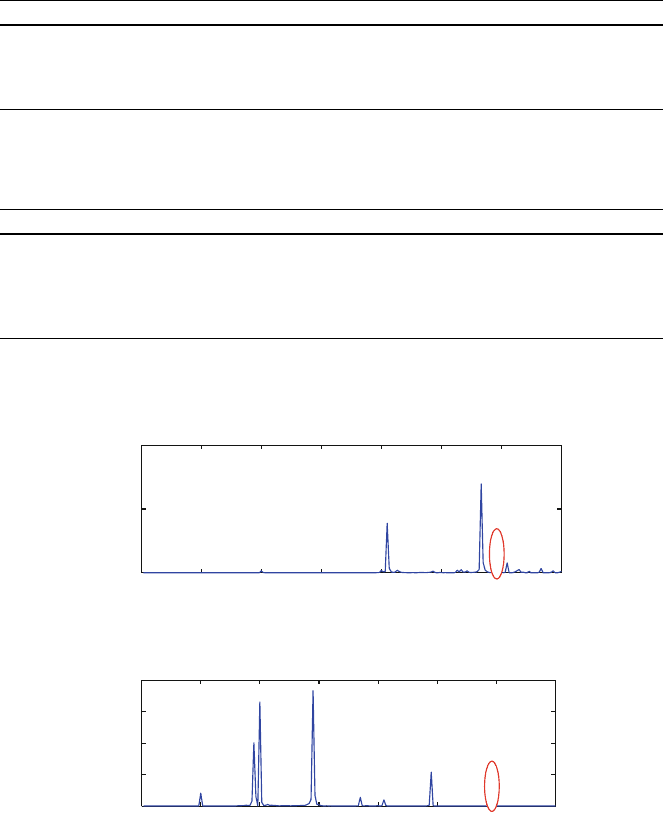
Fig. 7.8 Unified analysis for defect feature extraction at decomposition level 7. (a) PSD of the
healthy bearing and (b) PSD of the defective bearing
7.3 Application to Bearing Defect Diagnosis 117

Comparing the spectra of the healthy (Fig. 7.8a) and defective bearings
(Fig. 7.8b), it is seen that the inner raceway defect can be clearly identified by its
characteristic frequency at f
BPFI1
¼ 58.6 Hz. No distinctive peak is seen in the
spectrum of the healthy bearing at this frequency. The spectrum further indicates
several other major peaks at f
m
¼ 20 Hz, f
BPFO1
¼ 41 Hz, and f
BPFO2
¼ 56.5 Hz.
These are reflective of misalignment (at 20 Hz) of the defective bearing and
rotational characteristic of other bearing. For example, f
BPFO1
¼ 41 Hz is the ball
passing frequency of the type 6220 bearing, and f
BPFO2
¼ 56.5 Hz is found to be
related to ball rotation of a different bearing (cylindrical bearing type 2322 with its
vibration component indicated by the subscript “2”). This is based on the para-
meters of Z ¼14, D ¼ 33.5 mm, and d
m
¼175 mm, and the characteristic frequency
of the type 2322 bearing is calculated as f
BPFI2
¼83.4 Hz, f
BPFO2
¼56.5 Hz, f
BSF2
¼
50.1 Hz. This bearing structurally supports the rotating shaft in the bearing test bed.
Comparing with the Fourier analysis and the wavelet transform, the new, un ified
time scale frequency technique has shown to be more effective in extracting
bearing defect features. In that it not only reveals the existence of a localized
bearing defect, but also the defect characteristic frequency that is indicative of its
specific location (e.g., inner raceway).
7.3.2 Selection of Decomposition Level
When evaluating the unified technique, a particular decomposition level (e.g., level
7) is chosen for the wavelet transform. The selection of an appropriate level is based
on the signal sampling rate (or frequency) f
sample
and the defect characteristic
frequency f
char
. The relationship is expressed as:
f
sample
2
Lþ1
f
Char
f
sample
2
L
(7.31)
where L denot es the wavelet decomposition level. As an example, when the
sampling frequency is f
sample
¼ 10 kHz, the frequency range associated with
decomposition level L ¼ 7 is calculated as 39 78 Hz. In Table 7.2, the frequency
ranges covered by each of the decomposition levels under a 10 kHz sampling rate
are shown. The essence of finding the best-suited decomposition level when
wavelet transforming a dynamic signal is to ensure that its frequency range
½f
sample
=2
Lþ1
; f
sample
=2
L
covers the characteristic frequency of structural defect in
the bearing with the highest likelihood, if such a defect exists.
Table 7.3 lists the best-suited decomposition leve ls for analyzing bearing vibra-
tion signals specifically related to a localized inner raceway defect, under various
bearing rotational (or shaft) speeds. Since at 600 rpm, the defect characteristic
frequency f
BPFI1
¼ 58.6 Hz falls within the frequency range of 39 78 Hz, decom-
position level 7 is chosen initially for data analysis.
118 7 Wavelet Integrated with Fourier Transform: A Unified Technique
The importance of choosing proper decomposition level is illustrated in Fig. 7.9,
where the results of decomposing defective bearing signal at levels 6 and 8 are
shown. It is seen that none of the two levels (combined with the postspectral analysis)
are able to identify the defect characteristic frequency at f
BPFI1
¼ 58.6 Hz, due to the
Table 7.3 Best suited decomposition level for inner raceway defect frequency detection
Shaft speed (rpm) f
BPFI1
(Hz) Decomposition level Frequency range (Hz)
300 29.3 8 19 39
600 58.6 7 39 78
900 87.9 6 78 156
1,200 117.2 6 78 156
1,500 146.5 6 78 156
Table 7.2 Frequency range associated with each decomposition level at a 10 kHz sampling rate
Decomposition level Frequency range (Hz) Decomposition level (L) Frequency range (Hz)
1 2,500 5,000 5 156 312
2 1,250 2,500 6 78 156
3 625 1,250 7 39 78
4 312 625 8 19 39
0 10 20 30 40 50 60 70
0
1.5
3
x 10
−5
Frequency (Hz)
PSD (Watts/Hz)
f
BPFO2
Results from decomposition Level 6
0 10 20 30 40 50 60 70
0
2
4
6
8
x 10
−3
Frequency (Hz)
PSD (Watts/Hz)
f
m
f
u
Results from decom
p
osition Level 8
a
b
f
BPFO1
f
BPFO1
Fig. 7.9 Unified analysis using Daubechies 2 wavelet at levels 6 and 8. (a) Resutls from
decomposition level 6 and (b) results from decomposition level 8
7.3 Application to Bearing Defect Diagnosis 119