Gasch R., Twele J. (Eds.) Wind Power Plants: Fundamentals, Design, Construction and Operation
Подождите немного. Документ загружается.

462 14.1 The interconnected electrical grid
nowadays, wind power installation in Germany reached in 2006 a capacity of 20
GW (25 GW in 2009) which is a quite large proportion and therefore has a signifi-
cant impact on grid operation. In Germany, the total capacity of conventional
power generation was around 110 GW in 2006. The maximum grid load was
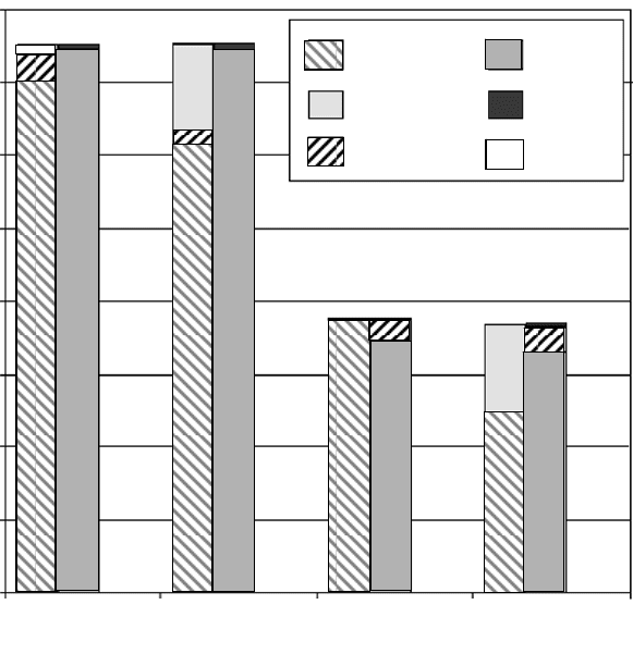
approx. 75 GW, the minimum approx. 35 GW. Fig. 14-2 shows that during off-
peak periods wind turbines were able to deliver nearly 30% of the total electricity
generation already in 2003. From time to time in several regions of Germany this
wind power share is even higher, e.g. in some grid sections in Northern Germany.
On very windy days, the produced wind power exceeds the minimum off-peak
load.
RU
GBIRL
S
N
UKR
MA
DZ TN
TR
BY
LT
LV
EE
RU
GBIRL
S
N
UKR
MA
DZ TN
TR
BY
LT
LV
EE
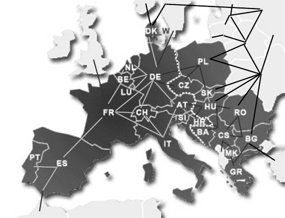
Fig. 14-1 European transmission grid UCTE (grey lines) with connections to the neighbouring
countries (black lines), dark grey: UCTE members, acc. [1, 2]
Future wind power installation is planned in Germany preferably offshore, there-
fore new grid capacities have to be built. However, it is imperative that the exist-
ing grid also be revised and reinforced swiftly because the changing structures in
the European electricity market require an international transportation system. In
Northern Europe, the grid tends to reach its peak load generally in winter. In the
Southern Europe this occurs partly in summer because of the increasing applica-
tion of air condition [2].
Fig. 14-3 shows the voltage levels of the interconnected grid in Germany and
the wind farm sizes suitable for connection. In general, the electricity from the
transmission grid (380 kV and 220 kV) is delivered to the consumer via distribution
14 Wind turbine operation at the interconnected grid 463
grids. The larger the wind farm the more economic the connection to a higher
voltage level. Grid operation is generally divided by voltage level and in Germany
also by region. This does not apply to all European countries. In Germany, there
are four large transmission grid operators and approx. 700 regional and local dis-
tribution grid operators (state of 2007).
Heavy load Heavy load Weak load Weak load
without wind with wind without wind with wind
Load
Grid losses
Ex-/ Import
Conventional
production
Stochastic wind
energy feeding
Pump storage
MW
80 000
70 000
60 000
50 000
40 000
30 000
20 000
10 000
0
Heavy load Heavy load Weak load Weak load
without wind with wind without wind with wind
Load
Grid losses
Ex-/ Import
Conventional
production
Stochastic wind
energy feeding
Pump storage
MW
Heavy load Heavy load Weak load Weak load
without wind with wind without wind with wind
Load
Grid losses
Ex-/ Import
Conventional
production
Stochastic wind
energy feeding
Pump storage
MW
80 000
70 000
60 000
50 000
40 000
30 000
20 000
10 000
0
Fig. 14-2 Electricity generation (left column) and consumption (right column) in 2003, without
and with wind power, acc. [3]
The planned wind farm capacity determines the required voltage level for the grid
connection and has to be stated in the application to the corresponding grid opera-
tor, cf. chapter 15.
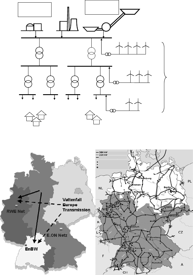
Fig. 14-4, left, shows the responsibility of the four transmission grid operators
and their high voltage grids. In the control areas of E.ON and Vattenfall the ratio
of wind power production to end user consumption is higher than e.g. in the region
of EnBW. Therefore, wind power is often exported to this region. Due to the
large-scale wind turbine installations in the Northern regions of Germany (Fig.
14-4 right, white areas) wind power production there is particularly high in com-
parison with local consumption.
464 14.1 The interconnected electrical grid
Conventional
power stations
Distribution grid
Consumer
Transmission grid
380 kV
220 kV
110 kV
20 kV
offshore > 300 MW
> 50 MW
20-50 WT
< 10 MW
1-5 WT
Wind farms
Pump storage
station
Conventional
power stations
Distribution grid
Consumer
Transmission grid
380 kV
220 kV
110 kV
20 kV
offshore > 300 MW
> 50 MW
20-50 WT
< 10 MW
1-5 WT
Wind farms
Pump storage
station
Fig. 14-3 Voltage levels of the grid in Germany
Operating voltage
High voltage DC transm.
AC DC conversion station
Transformer station
Town
Operating voltage
High voltage DC transm.
AC DC conversion station
Transformer station
Town
Fig. 14-4 Control areas of the four transmission grids and the high voltage grid in Germany [2, 4
left]
14 Wind turbine operation at the interconnected grid 465
14.1.2 Operation of the interconnected grid
The operation of the electrical grid in the individual control areas from their con-
trol centres aims to permanently adapt the generated power to the variable grid
load, i.e. the consumption. In Germany, the control areas correspond to the grid
areas of the four transmission grid operators. At the distribution grid level, the
schedules are produced based on contracts and experience values. These are then
reported to the transmission grid operator concerned who makes his prediction for
the next day based on the data received (i.e. day-ahead prediction).
Wind power generation
Conventional power generation
h
Weekend
Wind power generation
Conventional power generation
h
Weekday
0 2 4 6 8 10 12 14 16 18 20 22 h
Megawatt
20 000
18 000
16 000
14 000
12 000
10 000
8 000
6 000
4 000
2 000
0
Megawatt
20 000
18 000
16 000
14 000
12 000
10 000
8 000
6 000
4 000
2 000
0
0 2 4 6 8 10 12 14 16 18 20 22 h
Wind power generation
Conventional power generation
h
Weekend
Wind power generation
Conventional power generation
h
Weekday
0 2 4 6 8 10 12 14 16 18 20 22 h
Megawatt
20 000
18 000
16 000
14 000
12 000
10 000
8 000
6 000
4 000
2 000
0
Megawatt
20 000
18 000
16 000
14 000
12 000
10 000
8 000
6 000
4 000
2 000
0
0 2 4 6 8 10 12 14 16 18 20 22 h
Fig. 14-5 Typical daily load profile, E.O.N grid, Germany [5]
466 14.1 The interconnected electrical grid
Conventional
Power plants
f in Hz
50
49
Time
Power
5s
5s 30s
30s
15 min
15 min
60 min
60 min
Time
Control Area
Balance
Transmission system operator
Hour reserve
Primary control
Tertiary control
(Minute reserve)
Secondary control
Power - Frequency Control
Turbine speed
governor
Inertia
Conventional
Power plants
f in Hz
50
49
Time
Power
5s
5s 30s
30s
15 min
15 min
60 min
60 min
Time
Control Area
Balance
Transmission system operator
Hour reserve
Primary control
Tertiary control
(Minute reserve)
Secondary control
Power - Frequency Control
Turbine speed
governor
Inertia
Fig. 14-6 Reaction time of different types of grid control and supply of control power [6]
f
0
f= f (P
L
)
Load characteristic
f= f (P
E
)
Supplier characteristic
Power P
Grid frequency f
f
0
f= f (P
L
)
Load characteristic
f= f (P
E
)
Supplier characteristic
Power P
Grid frequency f
Fig. 14-7 Production and load characteristic curve of a grid [7]
Power generation and purchases are generally planned on a long-term basis and
well in advance. Fig. 14-5 shows two typical load curve diagrams for a control
area including wind power generation provided, one for a weekday and the other
for a week-end day.
The task of the control centre is to balance any difference between power con-
sumption (including export) and generation (including import). This is done by
switching on and off loads, like pumps in pumping storage plants, or power gen-
eration capacity. This requires reserve power which is ordered day-ahead and
should be as small as possible due to its high costs incurred. Since there are
always differences between predicted and real load, control power is always
required.
14 Wind turbine operation at the interconnected grid 467
The required control power is divided by its reaction time into primary, secondary
and tertiary control, Fig. 14-6. Primary control is immediately provided by the in-
ertia of the rotating mass in the power generation systems: generators and turbines
react with small changes in the rotational speed (i.e. conversion of kinetic energy)
to counteract fluctuations of frequency and voltage due to load variation, cf.
Fig. 14-7.
Secondary and tertiary control within the range of minutes, cf. Fig. 14-6, is
provided by fast-reacting power plants such as gas turbines or water turbines
(pumping storage plants). Nowadays, the share of the control power demand
which may be estimated in advance is invited for tender in a bidding forum on the
Internet.
The control areas contain so-called balance groups, consisting partially of sev-
eral electricity agents, for which the responsible of the balance group has to bal-
ance also the 15-min average of generation and demand.
Nowadays, on the one hand, the attainable accuracy of the prediction of the
required reserve power by the grid operator is reduced through the liberation of
the electricity trade which causes unpredictably high electricity transmission
capacities in the grids and, on the other hand, the fluctuation of wind power
generation. Short-term fluctuations of wind energy are not a major technical issue
for primary control since many effects in the time range of seconds and minutes
are balanced by the decentralised large-scale installation of the wind turbines.
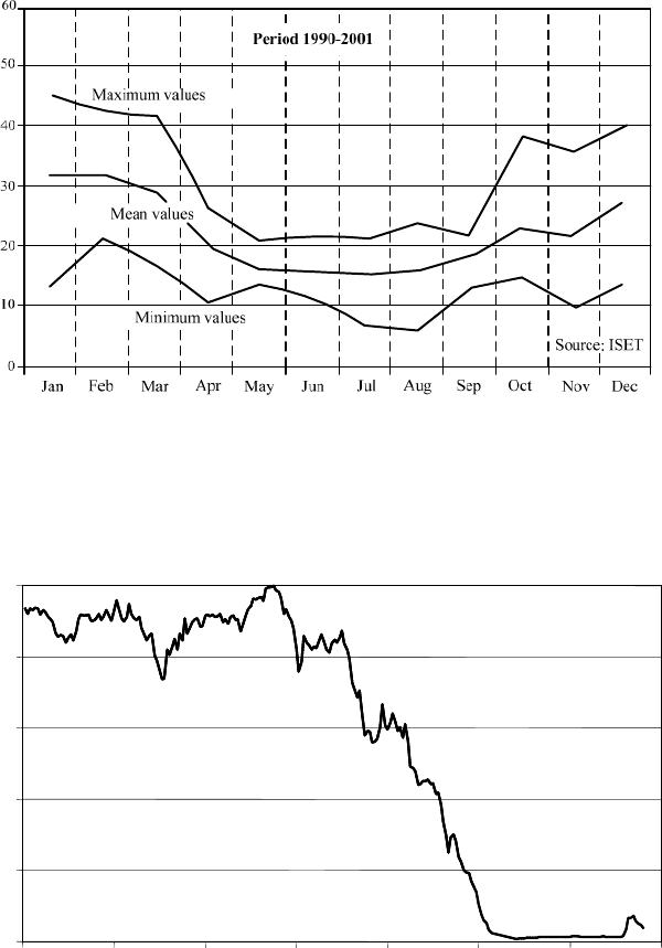
Seasonal variations such as the curve of the full-load equivalence (capacity factor)
have been well documented, Fig. 14-8.
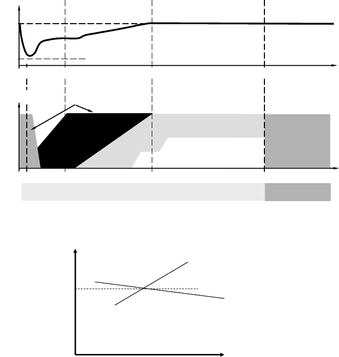
If, however, in a certain region there is a large gradient in the wind power pro-
duction due to rare weather conditions, Fig. 14-9, this may cause stability prob-
lems in the grid. Such rare occurrences may be a weather front, or a storm causing
many wind turbines to shut down. Therefore, grid operators now work with estab-
lished prediction methods in order to more accurately predict the curves of the
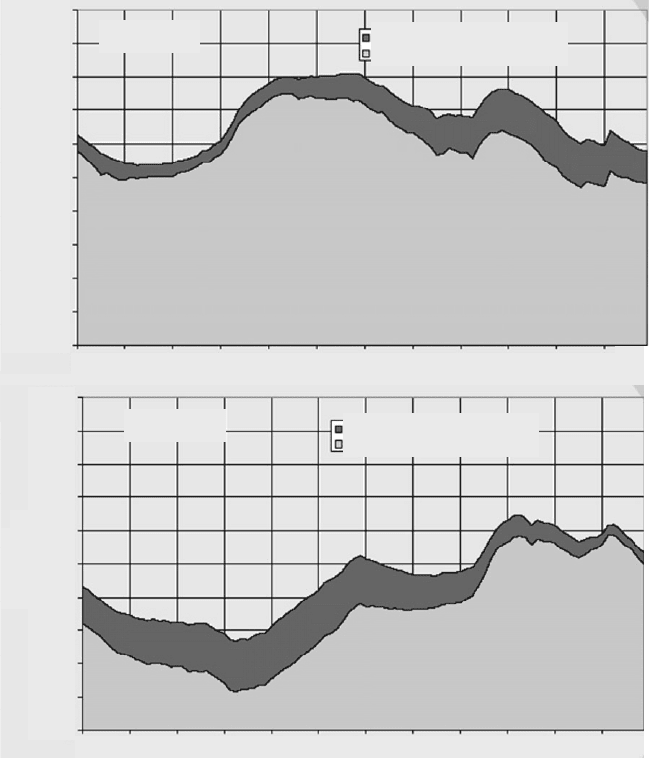
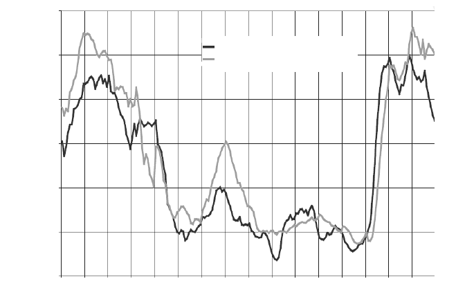
wind power generation [8]. Fig. 14-10 shows the comparison between the pre-
dicted and the actual measured wind power generation. The difference between
the day-ahead forecast (D+1) and the real wind power is around r 10%. This un-
certainty could be significantly reduced by short-term corrections, but these have
not yet been applied because of the set day-ahead forecast (i.e. period of 24 hours)
established in grid operation.
468 14.1 The interconnected electrical grid
Full load equivalence (capacity factor) in %
Fig. 14-8 Seasonal variation of wind power production [9]
0%
20%
40%
60%
80%
100%
06:00 12:00 18:00 00:00 06:00 12:00 18:00 00:00
-10% / h !!
Active power
production of a wind farm
Time in hours
0%
20%
40%
60%
80%
100%
06:00 12:00 18:00 00:00 06:00 12:00 18:00 00:00
-10% / h !!
Active power
production of a wind farm
Time in hours
Fig. 14-9 Example of a critical drop in active power production of a wind farm [10]
14 Wind turbine operation at the interconnected grid 469
'D\
:LQGSRZHUSURGXFWLRQ LQ0:
$FWXDO 0HDVXUHPHQW
'D\DKHDG IRUHFDVW '
'D\
:LQGSRZHUSURGXFWLRQ LQ0:
$FWXDO 0HDVXUHPHQW
'D\DKHDG IRUHFDVW '
:LQGSRZHUSURGXFWLRQ LQ0:
$FWXDO 0HDVXUHPHQW
'D\DKHDG IRUHFDVW '
Fig. 14-10 Day-ahead (24 hours) forecast of wind power and real wind power production [8]
Another measure of more harmonic grid operation with high shares of wind
energy input is the power production management for wind energy as required by
the grid codes published in 2003 [11]. Requirements of wind turbine operation are
derived from specific load situations in the grid. For example, if the grid load is
too small, the wind turbine should be able to provide negative control power by
reducing its power production.
If a relative high wind power production is predicted due to good winds, it is gen-
erally possible to operate the wind turbine with a reduced power output in order to
be able to provide positive control power by a wind turbine cluster [8].
This is tested but is currently not being implemented (2007) since the fluctuations
of the wind do not allow giving the required guarantee for the power production.
Since July 2009, the German Renewable Energy Sources Act includes the Ordi-
nance on System Services by Wind Energy Plants (System Service Ordinance –
SDLWindV); therefore more and more wind turbine types are now being certified
for actively support the grid.
Demand side management, i.e. control of the load, offers completely new pos-
sibilities for grid control. In order to avoid load peaks in the grid, large consumers,
such as cold storage houses, whose operation is not time-critical could be tempo-
rarily switched off to provide positive control power. Smart metering is another
method currently under development and test to provide decentralised intelligent
devices for consumer load control. This requires new standardised communication
to transfer and manage all the information.
470 14.2 Wind turbines in the interconnected electrical grid
A third method of optimising grid operation is balancing power generation and
consumption with the help of energy storage systems. Pump storage power plants
have been well-established for decades. At night, cheap electricity is used to pump
the water up into the reservoirs. During daytime peak-load the potential energy is
converted back into expensive control power by water turbines [12]. Short-time
storage systems (seconds to minute) such as flywheel storage systems, super cups
and even hydrogen production plants are currently being tested and will help to
stabilize the grid by smoothing the power input of wind farms. A flywheel storage
system is already offered in a hybrid system [13], cf. Fig. 13-25. Long-term stor-
age systems are the above mentioned established pump storage power plants, but
as well compressed air storage systems in underground caverns are considered as a
technical solution [12]. Hydrogen can be fuelled directly in biogas plants (e.g.
demonstration hybrid power plant Uckermark by Enertrag) or stored by feeding
into the German gas distribution system. This is designed allowing several percent
of Hydrogen in the gas mixture and has in Germany a huge storage capacity of 90
days gas supply for the entire country.
In order to allow higher transmission capacities in the existing electrical grid,
temperature monitoring of the overhead power lines has been successfully tested,
something which is technically quite simple to perform. Power line capacity is
currently being determined on the basis of a worst-case scenario which occurs at
special meteorological conditions without any wind. Wind farms would benefit
from power line temperature monitoring because when the power production is
high due to strong winds, the cooling of power lines by the wind is as well strong.
14.2 Wind turbines in the interconnected electrical grid
14.2.1 Technical requirements of the grid connection
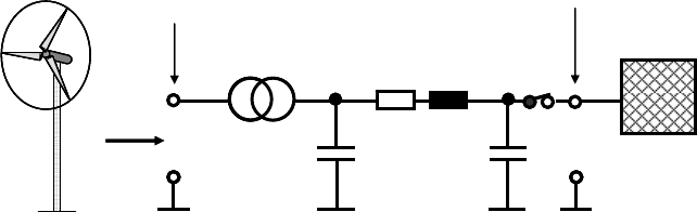
Fig. 14-11 shows the electrical equivalent circuit diagram of a typical wind turbine
grid connection to the medium-voltage grid. A distinction is drawn between the
wind turbine connection point at the feed line with the transformer, which in-
creases the voltage level, and the grid connection point. The latter is critical for
determining the potential grid connection capacity, which is given by the short-
circuit power at the grid connection point and the relevant properties of the feed
line with the transformer given in Fig. 14-11 as well. The maximum admissible
feed-in power P
max
at the grid connection point in the German medium-voltage
grid (20 kV) is 2% of the grid’s short-circuit power S
k
which is derived from the
nominal voltage U
N
and the short-circuit impedance Z
k
between the source and
the considered grid connection point:
14 Wind turbine operation at the interconnected grid 471
P
max
= 0.02 · S
k
where S
k
= U
N
2
/ Z
k
and Z
k
= (R
2
+ X
2
)
0.5
Z
k
is given by the ohmic resistance R and the reactance X =
Z
L calculated from
frequency
Z S
f
and inductance L. For larger wind farms which are connected
to the high-voltage grid (110 or 380 kV) by individual sub stations, a maximum
admissible power of 20% of the short-circuit power, or even more, may be al-
lowed.
R ȦL=X
Wind turbine
connection point
Grid connection point
Grid
Cable
20 kV
Transformer
R ȦL=X
Wind turbine
connection point
Grid connection point
Grid
Cable
20 kV
Transformer
Fig. 14-11 Equivalent circuit diagram of the connection of a wind turbine to the medium-voltage
power grid
During wind turbine operation, i.e. wind power input at the grid connection point,
the short-circuit power changes and is influenced by the wind turbine, the trans-
former and the feed line properties. On the one hand, a larger section of the feed
line and larger transformers allow higher admissible wind power input, but pro-
duce more installation costs, on the other hand. A more detailed calculation allows
grid connection facilities to be optimised [7, 14].
The technical equipment of the grid connection comprises:
x Transformer for adaption of the voltage level
x Circuit isolator and switchgear
x Measuring and metering facilities
x Filter
Grid connection regulations (grid codes) which no longer allow a wind turbine
is just shut down if grid faults occur have been in place since 2003. On the con-
trary, demands are now being made to support the grid at grid faults [11, 15, 16].
In this respect, only the behaviour of the entire wind farm at the grid connection
point is considered, not the single wind turbine. Therefore, the requirements may
be satisfied in different ways, and these grid codes mention following points:
x Switching-on procedure of the wind farm
x Reactive power production and consumption
x Active power production
x Behaviour at grid faults