George W. Stimson introduction to Airborne Radar (Se)
Подождите немного. Документ загружается.


Summary
The spectrum of a signal is the distribution of the signal’s
energy over the range of possible frequencies. One way of
explaining this distribution is to envision the signal as
being applied simultaneously to myriad lossless narrow-
band filters whose frequencies are infinitesimally closely
spaced and cover the complete range of frequencies. Each
filter can be envisioned as a pendulum suspended from a
frictionless pivot in a vacuum and driven by the reactive
force of an eccentric flywheel rotating at the frequency of
the input signal.
A pulsed radio frequency signal such as a radar transmits
is actually a continuous wave (carrier) whose amplitude is
modulated by a video signal having an amplitude of one
during each pulse and zero between pulses. So another way
of explaining how the energy of a pulsed radio wave is dis-
tributed in frequency is in terms of the sidebands produced
by the video modulating signal.
A continuous rectangular wave, such as the modulating
signal, can be constructed by adding together a series of
sine waves of appropriate amplitudes and phases, whose
frequencies are multiples of the wave’s repetition frequency,
plus a dc signal of appropriate amplitude—the Fourier
series. When the amplitude of the carrier wave is modulat-
ed by the pulsed wave, each of these sine waves produces
sidebands on either side of the carrier frequency.
The spectrum of a single pulse may be found by starting
with a pulse modulated wave that is endlessly repetitive
and decreasing the repetition frequency to zero. The spec-
trum of a pulse train of limited length can then be found by
treating each of the sine waves comprising the pulse modu-
lated wave as a single pulse the length of the train.
The spectrum of a pulsed carrier may also be explained
in terms of the progressive phase shift of the carrier relative
to the frequency to which a narrowband filter is tuned. For
a single pulse, nulls in the filter output occur at frequencies
for which the phase shift over the length of the pulse is
360° or a multiple thereof.
CHAPTER 17 Mysteries of the Pulsed Spectrum Unveiled
233
235
Sensing Doppler
Frequencies
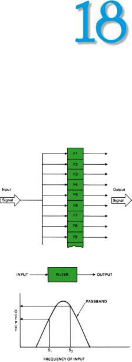
1. The received signals are applied in parallel to a bank of filters.
T
here are two basic reasons for sensing doppler
frequencies. One is to separate—resolve—
returns received simultaneously from different
objects. The other is to determine range rates.
In this chapter we will concern ourselves only with
sensing doppler frequencies and detecting differences
between them. We will see how this may be done with a
bank of doppler filters; then, in principle, how the filtering
is handled in both analog and digital mechanizations.
Finally, we will see why adequate dynamic range is so
essential in a doppler radar.
Doppler Filter Bank
How can a radar detect the echoes from many different
sources simultaneously and, in the process, sort them out
on the basis of differences in doppler frequency?
Conceptually, it is quite simple. The received signals are
applied to a bank of filters, commonly referred to as
doppler filters (Fig. 1).
Each filter is designed to pass a narrow band of frequen-
cies (Fig. 2). Ideally it produces an output only if the fre-
quency of a received signal falls within this band. Actually,
because of filter sidelobes, it may produce some output for
signals whose carrier frequencies lie outside the band. If
the return is to be sorted by range as well as doppler fre-
quency, a separate filter bank must be provided for each
range increment.
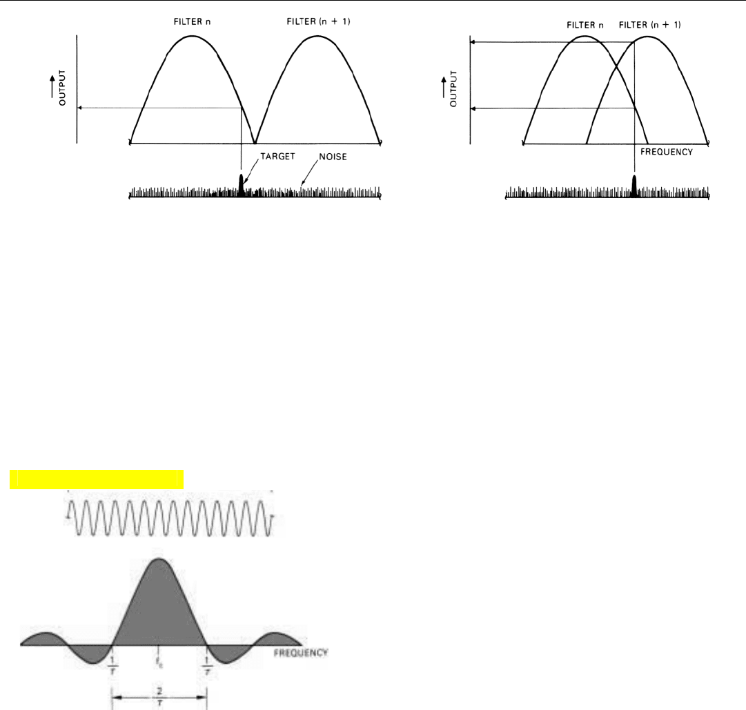
Moving up the bank from the lower end, each filter is
tuned to a progressively higher frequency. To minimize the
loss in signal-to-noise ratio occurring when adjacent filters
2. Neglecting sidelobes, each filter passes only a narrow band
of frequencies. The closer a signal is to the center frequency,
the greater the output.
PART IV Pulse Doppler Radar
236
straddle a target’s frequency, the center frequencies of the
filters are spaced so the passbands overlap (Fig. 3, above).
Thus, if a target’s doppler frequency gradually increases, an
output is produced, first, primarily from one filter; next,
more or less equally from that filter and the next filter up
the line; then, primarily from that second filter, and so on.
Bandwidth of the Filters. As we learned in Chap. 10, a
narrowband filter achieves its selectivity by integrating the
signals applied to it over a period of time. The width of the
band of frequencies passed by the filter depends primarily
upon the length of the integration time, t
int
.
Though you may not have realized it at the time, the
relationship between the bandwidth and t
int
was demon-
strated indirectly by the experiments of Chap. 16. There we
learned that the spectrum of a sinusoidal signal of duration
τ (single pulse) has a sin x/x shape such as that shown in
Fig. 4. Each point on this plot corresponds to the output
the signal would produce from a narrowband filter that
integrates the signal throughout its entire duration. The
plot was in fact obtained by progressively tuning the filter
to each of a great many different frequencies.
We can find the relationship between the filter’s band-
width and t
int
simply by repeating the experiment as follows:
• Hold the tuning of the filter constant and progressive-
ly change the frequency of the applied signal.
• Limit the filter’s integration time (t
int
) and make the
signal at least as long as t
int
.
Now, instead of representing the spectrum of the applied
signal, the plot represents the output characteristic of the
narrowband filter.
The central lobe of this characteristic is the filter’s pass-
band, and the center frequency of the central lobe is the fil-
ter’s resonant frequency. Since t
int
in this last experiment
corresponds directly to τ in the earlier one, the filter’s null-
3. To minimize the loss of output when a signal lies between the center frequencies of two filters, the passbands overlap.
4. Spectrum of sinusoidal signal of duration,
τ.
Click for high-quality image
to-null bandwidth is 2/t
int
(Fig. 5). For ease of comparison,
the horizontal scale factor used in this figure was adjusted
to make the positions of the nulls the same as in Fig. 4.
Bear in mind, though, that integration times are generally
on the order of milliseconds, whereas pulse widths are on
the order of microseconds.
As with the mainlobe of an antenna radiation pattern, a
more useful measure of filter bandwidth than the null-to-
null width is the width of the central lobe at the points
where the power of the output is reduced to half its maxi-
mum value—the 3-dB bandwidth. Just as with a uniformly
illuminated antenna, that width is approximately half the
null-to-null width.
BW
3dB
≅
1
t
int
To realize this bandwidth, of course, the duration of the
applied signal must at least equal t
int
. In fact, filter band-
width is often selected on the basis of the maximum avail-
able integration time.
If the radar is pulsed, the number of pulses that must be
integrated to achieve a given bandwidth is equal to t
int
times
the PRF. A useful rule of thumb derived from this relation-
ship is, the 3-dB bandwidth of a filter equals the PRF divided by
the number of pulses integrated.
The bandwidth given by the above equation, it should be
noted, is the minimum achievable bandwidth. Depending
on the mechanization, a practical filter may have a substan-
tially broader passband as a result of losses or, in digital
mechanizations, deliberately introduced “weighting.”
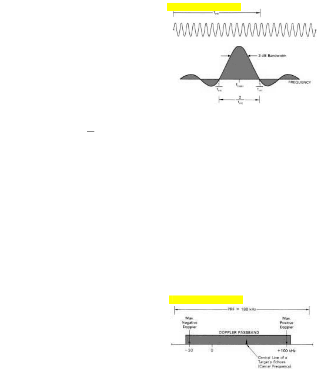
Passband of the Filter Bank. If the PRF is greater than
the spread between the maximum positive and negative
doppler frequencies for all significant targets—or if the
radar is not pulsed—enough filters must be included in the
bank to bracket the anticipated doppler frequencies. For
example, if the PRF were 180 kilohertz, the maximum
anticipated positive doppler frequency 100 kilohertz, and
the maximum anticipated negative doppler frequency –30
kilohertz (Fig. 6), then the passband of the filter bank
would have to be at least 100 + 30 = 130 kHz wide to pass
the return from all targets.
On the other hand, if the PRF is less than the anticipated
spread in doppler frequencies (as it often must be made to
reduce range ambiguities), the passband of the bank should
be made no greater than the PRF. The reason, of course, is
that the spectral lines of a pulsed signal occur at intervals
equal to the PRF, and it is desirable that any one target
CHAPTER 18 Sensing Doppler Frequencies
237
6. If the PRF is greater than the spread between the maximum
positive and negative doppler frequencies, the doppler pass-
band should be made wide enough to encompass these fre-
quencies.
5. Output characteristic of a narrowband filter to which a signal
at least as long as the filter integration time, t
int
is applied.
Click for high-quality image
Click for high-quality image
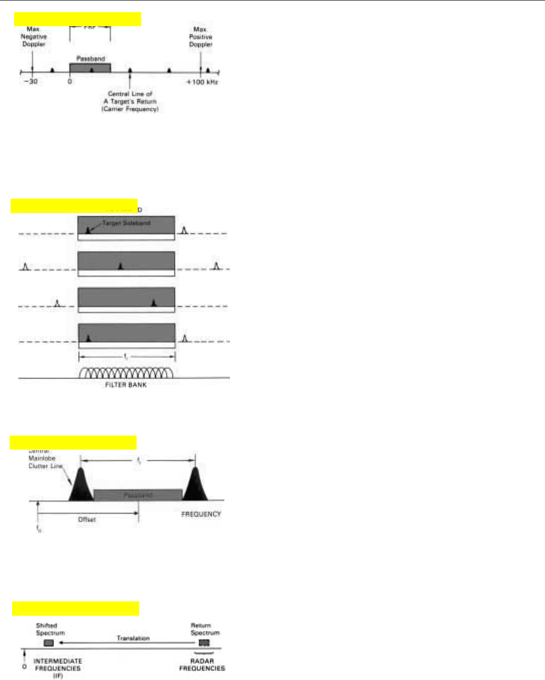
10. For analog filtering, the doppler spectrum is shifted to a low
intermediate frequency.
PART IV Pulse Doppler Radar
238
appear at only one point in the filter bank’s passband.
Depending on the target’s doppler frequency, the spectral
line falling within the passband in this case may not be the
target’s central one (carrier frequency). It may be one of the
lines (sideband frequencies) above or below it (Fig. 7). But
since the lines are harmonically related, which one it is
doesn’t matter. What is important is that for each target one
and only one line falls within the passband.
That this requirement is satisfied when the width of the
passband equals f
r
is illustrated in Fig. 8. It shows a portion
of the spectrum of a target’s echoes for each of several pro-
gressively higher doppler frequencies. These frequencies all
happen to be such that the target’s central line (carrier fre-
quency) lies outside the figure. Superimposed over the
spectrum is a mask with a window in it, representing the
passband of a filter bank, f
r
hertz wide.
In the first plot of Fig. 8, one of the target’s spectral lines
falls in the lower end of the passband. With the progressive
increase in doppler frequency, in subsequent plots this
same line appears progressively farther up in the band. In
the last plot, the doppler frequency is sufficiently high that
the line we have been observing is actually above the pass-
band; the next lower frequency line now appears in the
lower end of the passband.
It can similarly be shown that the target will always
appear somewhere within the passband regardless of where
we position it. Without causing any problems, therefore, we
can shift the passband up or down relative to the transmit-
ter frequency, f
0
. It is, in fact, often advantageous to do so.
In low and medium PRF radars, for example, the passband
is generally made somewhat less than f
r
hertz wide and
shifted up in frequency so it conveniently lies between the
central and next higher lines of the ground return that is
received through the antenna’s mainlobe (Fig. 9). (Actually,
to simplify mechanization, the frequencies of the doppler
filters are not changed. Instead the spectrum of the radar
return is shifted relative to the filter bank. The net result,
however, is the same.)
The doppler filters making up the bank may be either
analog or digital. While both types perform essentially the
same function, they differ radically in implementation.
Analog Filters
These are essentially tuned electrical circuits. Since with
them it is easier to obtain the desired selectivity at compara-
tively low radio frequencies, the spectrum of the radar
return is generally translated to an intermediate frequency
on the order of 50 megahertz or less (Fig. 10). In the
7. If the PRF is less than the spread of doppler frequencies, the
passband should be made no wider than the PRF so that a tar-
get will appear at only one point within the band.
8. If the width of the filter bank’s passband equals f
r
or less, only
one line of the target’s spectrum will fall within it, regardless
of the target’s doppler frequency.
9. Passband may be offset from f
o
to avoid mainlobe clutter.
Click for high-quality image
Click for high-quality image
Click for high-quality image
Click for high-quality image
1. The resonant frequency is
1/2 π
LC, where L is the
inductance and C is the
capacitance.
process, track is kept of the position of the doppler spec-
trum relative to the transmitter (or in some cases mainlobe
clutter) frequency.
Filters’ Basic Function. What the filters actually are sen-
sitive to is not frequency, per se, but phase shift—a doppler
frequency being, in fact, a continuous phase shift. To see
how an analog filter would detect this shift, it is necessary
to know a little more about the filter.
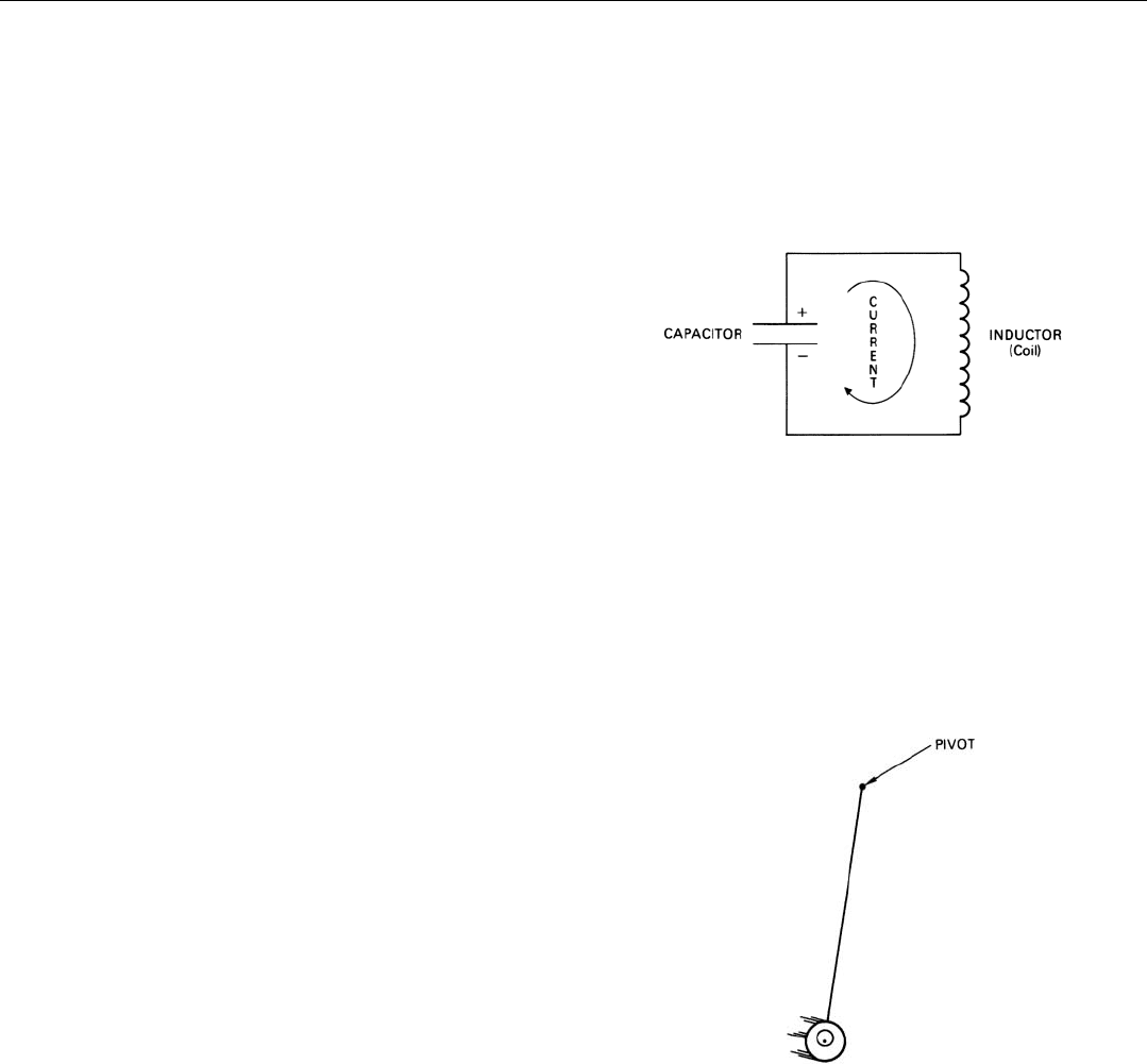
In its simplest form, a tuned electrical circuit consists of
a capacitor and an inductor (Fig. 11). If a charge is placed
on the capacitor, a current surges back and forth between
the plates of the capacitor through the inductor, alternately
discharging the capacitor and charging it back up again
with the opposite polarity. The number of these cycles com-
pleted per second depends upon the capacitance of the
capacitor and the inductance of the inductor and is called
the resonant frequency of the circuit.
1
The inductor and
capacitor naturally have some losses (resistance). Con-
sequently, the passband is invariably wider than 1/t
int
. The
lower the losses, the closer the passband approaches this
limit.
Analogy to a Pendulum. As with the lossless narrowband
filter of the previous chapter, the response of a tuned elec-
trical circuit to an alternating current signal is analogous to
the more readily visualized response of a pendulum to a
series of impulses (Fig. 12). The first impulse starts the
pendulum swinging. Subsequent impulses increase the
swing. If the pendulum is allowed to swing freely for a time
and another series of impulses is applied, they will do one
of three things. If they are in phase with the swing, they
will increase it. It they are not quite in phase with it, they
will not increase it as much. And if they are out of phase
with it, they will tend to damp it out. When the process is
repeated many times, the amplitude of the swing builds up
to a large value if, and only if, there is a continuity of phase
from one series of impulses to the next (i.e., the impulses
are coherent) and the frequency of the impulses is the same
as the pendulum’s natural frequency. Because of friction
with the air and in the pivot, some of the energy imparted
to the pendulum is lost, so the oscillation builds up some-
what more slowly than might otherwise be expected and
dies out after the impulses stop.
The impulses, of course, correspond to the individual
cycles of the signal applied to the electrical circuit. Each
series of impulses corresponds to a received pulse. The
amplitude to which the swing builds up corresponds to the
amplitude of the filter’s output.
2
CHAPTER 18 Sensing Doppler Frequencies
239
11. An analog filter is a tuned electrical circuit—in simplest form,
a capacitor and an inductor.
12. Response of a tuned electrical circuit to an alternating current
signal is analogous to the response of a pendulum to a series
of impulses applied by an eccentric flywheel driven by an
electric motor.
2. The pendulum’s motion cor-
responds to the current; the
restoring force on the pen-
dulum, to the charge on the
capacitor; the mass, to the
inductance of the inductor;
and the friction, to the resis-
tance of the tuned circuit.
PART IV Pulse Doppler Radar
240
Why is the tuned circuit called an analog filter in the first
place? Because the electrical characteristics of the circuit
elements are analogous to the mathematical operation nec-
essary to isolate a given band of frequencies—integration of
the current by the capacitor, differentiation of the current
by the inductor, and weighting by the resistance.
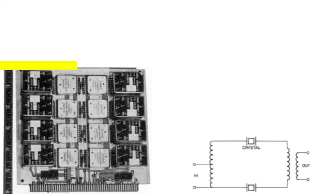
Practical Filters. To achieve the desired sharpness of
tuning, a quartz crystal, which has the same electrical char-
acteristics as an exceptionally sharply tuned combination of
capacitance and inductance, is substituted for the capacitor
and inductor (Fig. 13). When wider bandwidths are
required, two or more crystals having slightly different reso-
nant frequencies may be used (Fig. 14).
13. Portion of a bank of analog doppler filters used in a represen-
tative airborne radar. (The black units are filters; the smaller
units, threshold detectors.)
14. Circuit of an analog filter in which two crystals tuned to slightly dif-
ferent frequencies are used to provide a slightly broader passband
than that of a single crystal.
To detect the presence of a target, the filter output may
be applied to a threshold detector.
Digital Filtering
As we just saw, an analog filter is implemented with cir-
cuit elements whose electrical characteristics are analogous
to mathematical operations. By contrast, a digital filter is
implemented with the logic of a digital computer, which
performs these same operations numerically—a process
called “forming” the filter digitally. Why do the filtering this
way?
There are several reasons. Perhaps the most compelling is
accuracy. Once the radar return has been accurately con-
verted to digital numbers, all subsequent signal processing
is essentially error-free. (There are, of course, quantization
and round-off errors, but these can be kept within accept-
able bounds through proper system design.) All results are
repeatable, no adjustments are required, and performance
doesn’t degrade with the passage of time.
Also, where a great many doppler filters are required and
a variety of operating modes is desired, the size and weight
of the equipment needed to implement the radar can be
substantially reduced through digital filtering. In fact, it is
Click for high-quality image
only through digital filtering that many of today’s advanced
multimode airborne radars are even feasible.
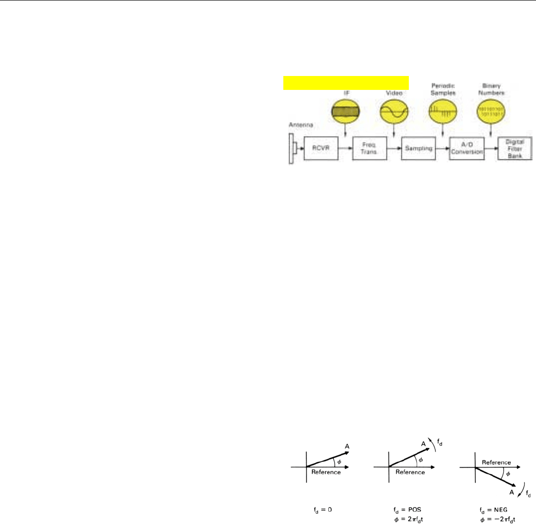
Converting the radar return into digital form for input to
the computer requires some additional operations.
Generally, a radar receiver’s intermediate frequency is too
high to make analog-to-digital conversion convenient, so at
the outset (Fig. 15) the receiver output is translated down-
ward to the video frequency range—zero (dc) to several
megahertz. The resulting video signal, it might be noted, is
similar to the signal which controls the intensity of the
cathode ray beam that “paints” the pictures on a TV screen.
Since this signal is continuously varying and the numbers
into which it will be converted are discrete,
3
the signal
must be sampled at short intervals. Finally, each sample
must be converted to an equivalent binary digital number.
The numbers are applied as inputs to the computer that
forms the filters. In the following paragraphs, each of these
steps will be explained briefly.
Translation to Video Frequencies. The radar receiver’s IF
output signal is translated to video frequencies by compar-
ing it with a reference signal whose frequency corresponds
to the transmitter frequency, f
0
, translated to the receiver’s
IF. (In some cases, an offset is added to the reference fre-
quency, but we will assume no offset here.)
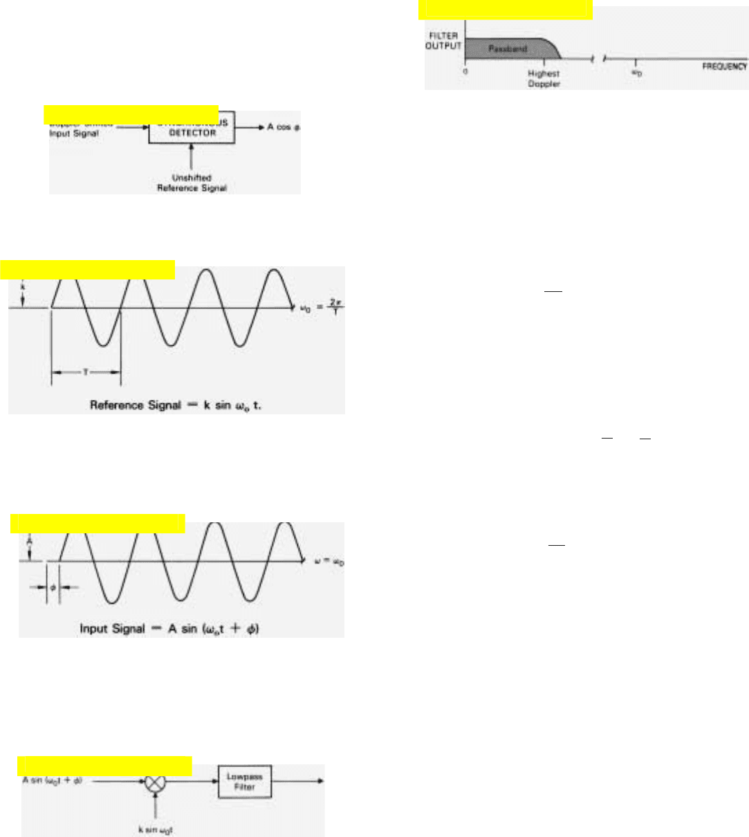
Before considering how the comparison is made, it will
help to have a clear picture in mind of the relationship
between the reference signal and the IF output produced by
a target. This relationship is illustrated for three representa-
tive situations by the phasor diagrams of Fig. 16. In each
diagram, the imaginary strobe light that illuminates the
phasors is synchronized with the reference signal, so the
phasor representing it remains fixed.
In the first diagram, the frequency of the target signal
equals f
0
—no doppler shift. Consequently, the phasor rep-
resenting the target return also remains fixed. The angle, φ,
corresponds to the phase of the target signal relative to the
reference signal.
In the second diagram, the target has a positive doppler
frequency. The target phasor, therefore, rotates counter-
clockwise, with φ increasing at a rate proportional to the
doppler frequency, f
d
.
φ
⋅
= 2π f
d
radians per second
In the third diagram, the target’s doppler frequency is
negative; so the target’s phasor rotates clockwise. Again, the
phase angle φ changes at a rate proportional to the doppler
frequency.
CHAPTER 18 Sensing Doppler Frequencies
241
15. For digital filtering, the IF output of the receiver must be trans-
lated to video frequencies, sampled, and converted to binary
numbers.
16. Three possible relationships between the reference signal sup-
plied to the synchronous detector and the IF output (A) pro-
duced by the return from a target.
3. Discontinuous in time—i.e.,
the value of each number is
separate and distinct from
that of the preceding number.
Click for high-quality image
PRODUCTS OF THE MULTIPLICATION. By means of a simple
trigonometric identity, the input signal can be shown to consist
of two components:
(1) (2)
A sin (
ω
0
t
) A (sin
) (cos
ω
0
t) A (cos
) (sin
ω
0
t)
When term 1 is multiplied by the expression for the reference signal
(k sin
ω
0
t), the product
Because of its high frequency (2
ω
0
), the signal represented by this
product is rejected by the lowpass filter.
However, when term 2 is multiplied by k sin
ω
0
t, the product expands
mathematically into two terms.
kA (cos
) (sin
2
ω
0
t)
kA (cos
)
[
1
1
cos 2
ω
0
t
]
2 2
Because of its high frequency (2
ω
0
), the signal represented by the
second of these terms is also rejected by the lowpass filter. The sole
output of the filter, then
kA
(cos
)
2
If k is taken as being equal to two
V
output
A cos
where A is proportional to the amplitude of the input signal and is the
signal’s phase relative to the reference signal. Since this is a cosine
function, it is called the
in-phase
or
I output
.
REFERENCE SHIFTED 90°. lf we shift the phase of the reference signal,
i.e., insert a delay which makes the signal applied to the detector equal
k sin (
ω
0
t 90°), the same input signal will produce an output equal to
A cos (
90°). Since the cosine of any angle minus 90° equals the sine
of the angle, the output voltage is proportional to the
sine
of
.
V
output
A cos
Again, “A” is proportional to the amplitude of the input signal and
is the
signal’s phase relative to the unshifted reference. Since this is a cosine
function,
is called the
quadrature
or
Q output
.
PART IV Pulse Doppler Radar
242
kA (sin
) (cos
ω
0
t) (sin
ω
0
t)
kA
(sin
) (sin 2
ω
0
t)
2
HOW THE SYNCHRONOUS DETECTOR WORKS
BASIC FUNCTION. The synchronous detector discussed in the text
compares a doppler-shifted input signal with an unshifted reference signal
and produces an output whose amplitude is proportional to the amplitude
(A) of the input signal times the cosine of the phase (
) of the input signal
relative to the reference signal.
For purposes of explanation, we’ll assume here that the reference signal
has an amplitude k and a frequency of ω
0
radians per second.
Since a doppler frequency shift is actually a continuous phase shift, at any
one instant of time the doppler-shifted input signal can be thought of as
having a frequency equal to the reference frequency (ω
0
) but being shifted
in phase relative to the reference signal by
radians.
WHAT THE DETECTOR DOES. In essence, the detector does two things:
(1) multiplies the instantaneous value of the input signal by the instanta-
neous value of the reference signal and (2) applies the resulting signal to a
lowpass filter.
The filter s passband is wide enough to pass the highest doppler frequency
that may be encountered but narrow enough to reject completely any signal
whose frequency is as high as or higher than ω
0
.
Click for high-quality image
Click for high-quality image
Click for high-quality image
Click for high-quality image
Click for high-quality image
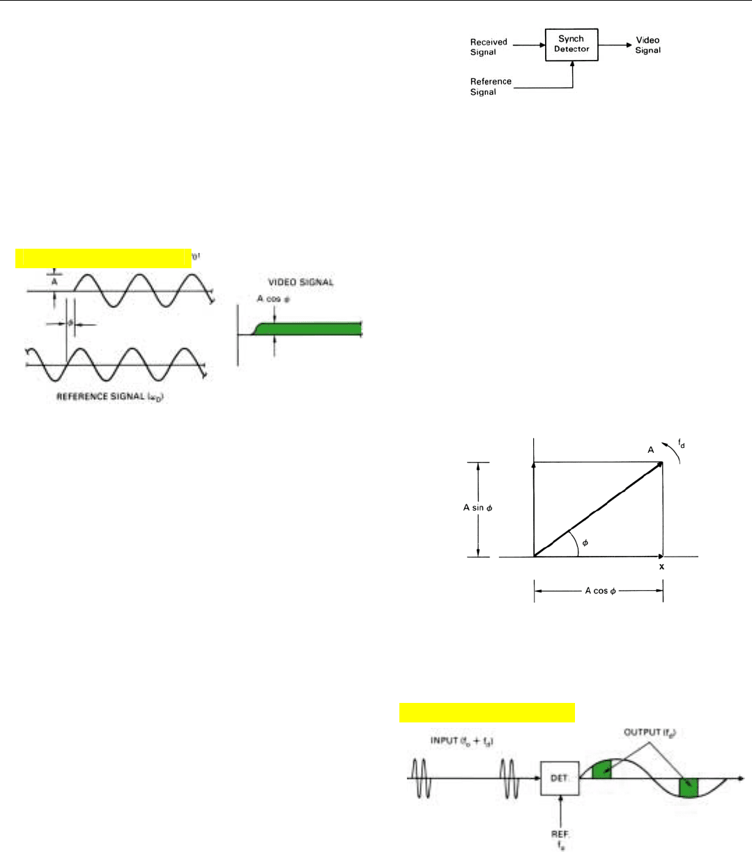
Now, the IF output signal is compared to the reference
signal by a circuit called a synchronous detector (Fig. 17). As
explained in detail on the facing page, it produces an out-
put voltage proportional to the amplitude of the received
signal times the cosine of the phase angle, φ, relative to the
reference signal.
V
output
= A cos φ
where A is proportional to the amplitude of the received
signal and φ is its phase (Fig. 18).
CHAPTER 18 Sensing Doppler Frequencies
243
17. For digital filtering, a synchronous detector translates the
received signal to the video frequency range.
18. Amplitude of output pulse is proportional to cosine of received
pulse’s phase relative to the reference signal.
19. The output which a received signal produces from a single
synchronous detector may be visualized as the projection of
the phasor representation of the received signal on the x axis.
We can conveniently visualize the detector’s output,
therefore, as the projection of the phasor representation of
the received signal on the x axis, Fig. 19. If the target’s
doppler frequency is zero, the output voltage (x) will be
constant.
Its exact value may lie anywhere between zero and A,
depending upon the signal’s phase. If the target’s doppler
frequency is not zero, the output (x) will be a cosine wave
having an amplitude, A, and a frequency equal to the tar-
get’s apparent doppler frequency.
If the radar is pulsed, unless the duty factor is very high,
the output pulse produced by each target echo will repre-
sent only a fraction of a cycle of the target’s apparent
doppler frequency. Nevertheless, by observing successive
pulses, we can get an idea of the amplitude of the target
return and tell its doppler frequency (Fig. 20).
But we won’t be getting everything out of the echoes that
we might. Since x varies cyclically as the phasor rotates, we
will on average throw away half the received energy—the
component A sin φ in Fig. 19. Also, in certain applications
where the time-on-target is short compared to the period of
the doppler frequency, the echoes may all be received when
cos φ is so small that they cannot be detected.
More importantly, we will not be able to tell in which
direction the phasor is rotating. For a given rate of rotation,
the projections of the phasor on the x axis are the same,
20. Output of the synchronous detector for a pulsed input signal
having a duty factor of 25 percent and an apparent doppler
frequency equal to half the PRF.
Click for high-quality image
Click for high-quality image