George W. Stimson introduction to Airborne Radar (Se)
Подождите немного. Документ загружается.

PART IV Pulse Doppler Radar
244
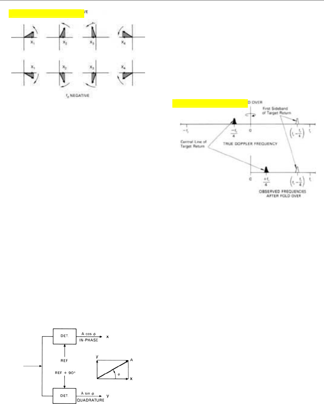
whether the phasor rotates clockwise or counterclockwise
(Fig. 21). On the basis of these projections alone, we have
no way of telling whether the target’s doppler frequency is
positive or negative. Indeed, in simple MTI radars, which
process only one component of the return, all doppler fre-
quencies are indicated as positive. The negative half of the
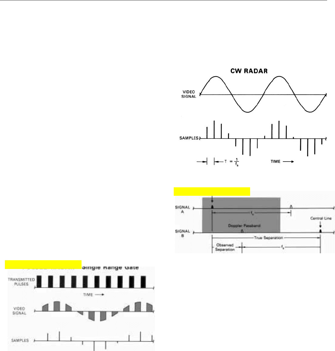
doppler spectrum is said to be “folded over” onto the posi-
tive half. Thus, a target whose doppler frequency is, say,
–
1
/4f
r
will also appear to have a doppler frequency of +
1
/4
f
r
(Fig. 22).
The above limitations can be eliminated by simultane-
ously applying the IF output to a second synchronous
detector to which the same reference signal is applied, but
with a 90° phase lag.
4
Since the cosine of (φ – 90°) equals
the sine of φ, the output voltage of this detector is propor-
tional to the amplitude of the target return times the sine of
the phase angle, φ, relative to the unshifted reference.
V
output 2
= A sin φ
We can conveniently visualize this second output as the
projection of the phasor representation of the target return
onto the y axis, as in Fig. 23. Now, if the second detector’s
output (y) lags behind the first detector’s output (x), we
know that the phasor is rotating counterclockwise: the tar-
get’s doppler frequency is positive. On the other hand, if y
leads x, we know that the phasor is rotating clockwise: the
target’s doppler frequency is negative.
The x projection is called the in-phase or I component; the
y projection, the quadrature or Q component. Together, the
two projections describe the phasor completely. Their vec-
tor sum equals the length of the phasor (A).
22. If only one component of the return is processed, the negative
portion of the doppler spectrum will be folded over onto the
positive portion.
23. Two channel detector system. Reference frequency for quadra-
ture channel has 90
° phase lag.
4. To avoid imbalances, a single
detector and A/D converter
may instead be alternately
used for I and Q channels.
The sampling rate must then
be doubled.
21. Detector output for successive echoes. In-phase or quadrature
component alone is the same for both positive and negative
doppler frequencies.
Click for high-quality image
Click for high-quality image
Their ratio,
5
together with their algebraic signs, unam-
biguously indicate the phase angle, φ; hence, both the rate
and the direction of the phasor’s rotation.
Sampling the Video Signals. So that the continuously
varying outputs of the I and Q detectors can be converted
to digital numbers, they must be sampled at short intervals
of time. Because the outputs may be rapidly varying, the
sampling rate must be precisely controlled to avoid intro-
ducing errors. Depending upon the design of the radar, the
rate may range anywhere from a few hundred thousand to
hundreds of millions of samples per second.
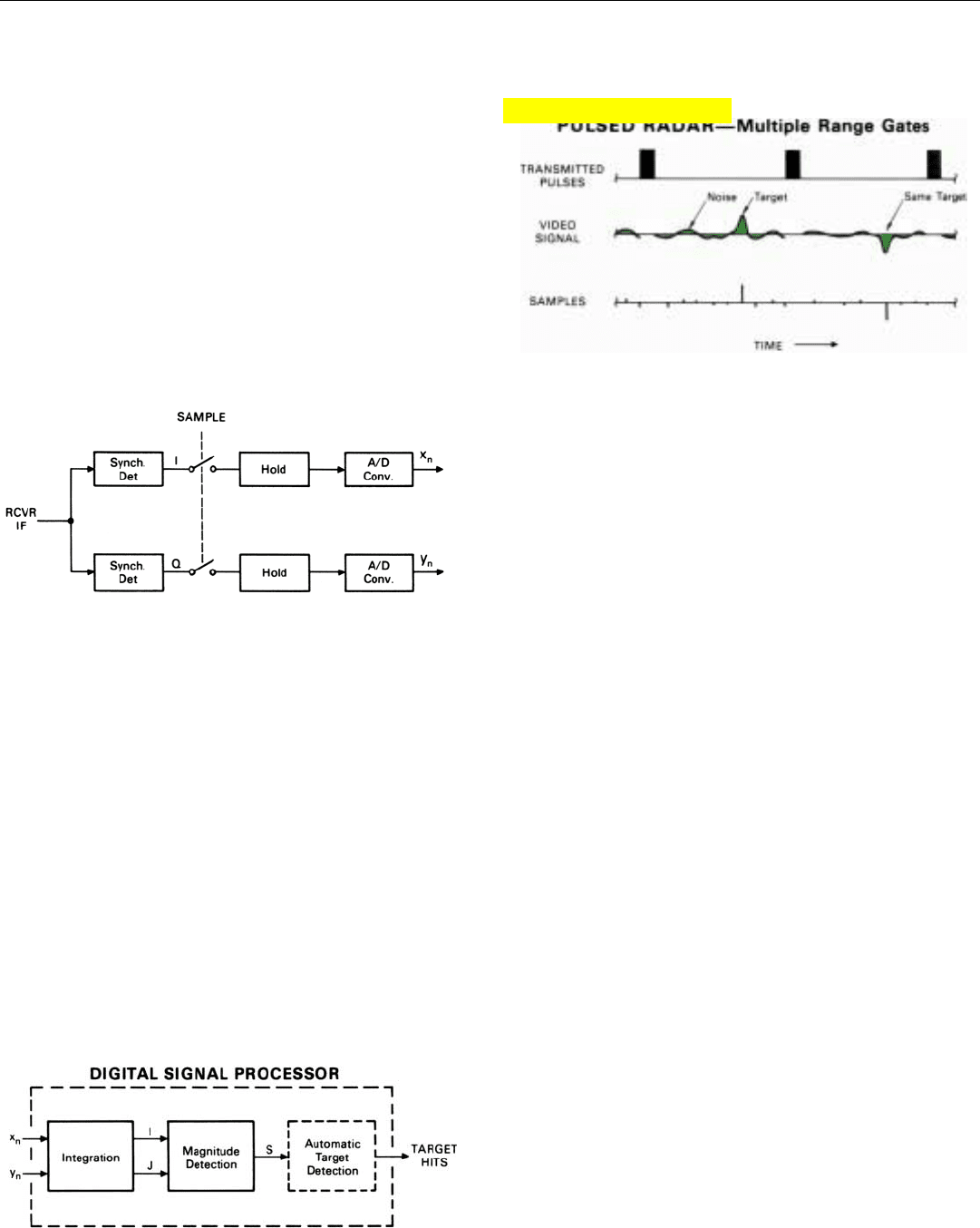
In a CW radar, the rate must at least equal the width of
the band of frequencies to be passed by the doppler filter
bank. If the rate is less than this, the sampling will intro-
duce frequency ambiguities. The reason is that sampling
converts the CW signal into a pulsed signal whose repeti-
tion frequency is the sampling rate (Fig. 24). The spectral
lines of a pulsed signal, of course, recur at intervals equal
to the repetition rate. Consequently, if two signals are
received whose true doppler frequencies differ by more
than the sampling rate, the observed difference in their fre-
quencies will be the true difference minus the sampling rate
(Fig. 25).
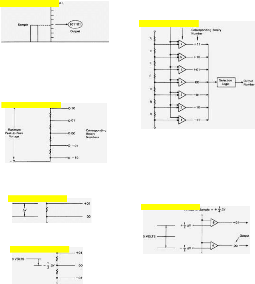
In a pulsed radar, sampling corresponds to the range gat-
ing performed in analog mechanizations. If only one sample
is taken during each interpulse period—as might be done if
the PRF were high and the duty factor close to 50 percent—
the radar is said to have a single range gate (Fig. 26).
CHAPTER 18 Sensing Doppler Frequencies
245
24. When a CW video signal is sampled, it is converted to a pulsed
signal whose PRF is the sampling rate, f
s
.
25. Doppler spectra of two CW signals after sampling when sampling
rate f
s
is less than signals’ true frequency separation.
5. Actually, the ratio is the tan-
gent of the phase angle; the
arctangent of the ratio is the
phase angle.
Obviously, the sampling rate in this case would be the PRF.
Where the equivalent of more than one range gate is
required, the sampling rate must equal the PRF times the
number of range gates. Each sample then represents the
return of a single pulse from a given range increment—or,
26. If only one sample is taken between transmitted pulses, the
radar has the equivalent of a single range gate. Note that the
samples are taken at the end of the sampling intervals.
Click for high-quality image
Click for high-quality image
29. Functions performed by a digital filter during each successive
integration time, t
int
.
PART IV Pulse Doppler Radar
246
if range is ambiguous, from a number of range increments
separated by the unambiguous range, R
u
(Fig. 27).
27. If more than one sample is taken between transmitted pulses, suc-
cessive samples represent returns from different ranges (or sets of
ranges if range is ambiguous).
28.
At regular intervals, I and Q video signals are momentarily sam-
pled. Samples are held long enough to be converted to numbers.
In either case, the sampling is generally performed with
“sample-and-hold” circuits. Separate circuits are provided
for the outputs of both the I and the Q detector (Fig. 28).
At precisely the required intervals, these circuits sense the
instantaneous values of the output voltages. They hold the
samples long enough for them to be converted to digital
numbers, then dump them, and the process repeats.
Analog-to-Digital Conversion. Exactly how this conver-
sion is done depends upon the length of time between sam-
ples, the maximum rate at which the voltage being sampled
may change, the required conversion accuracy, cost consid-
erations, and so on.
In essence, though, most mechanizations are much the
same. The A/D converter compares the voltage of each sam-
ple it receives with a succession of progressively higher
voltages of precisely known value. When the closest of
these is found, the converter outputs a binary number equal
to the known voltage. The panel on the facing page illus-
trates in general how this process might be performed.
Separate converters (or converter channels) are provided
for the I and Q samples. The continuous stream of binary
numbers emerging from the converter(s) is supplied to the
computer which forms the doppler filters.
Forming the Filters. During each successive integration
time, t
int
, the computer mathematically forms a separate
bank of doppler filters for every range gate.
Each filter in the bank for a given range gate receives as
inputs the same set of numbers (x
n
, y
n
) from the A/D con-
verter (Fig. 29). If return is being received from a target,
each pair of numbers constitutes the x and y components of
one sample of a signal whose amplitude corresponds to the
Click for high-quality image
CHAPTER 18 Sensing Doppler Frequencies
247
HOW AN A/D CONVERTER WORKS
WHAT IT DOES. In essence, an analog-to-digital converter compares each
sample of the signal that is to be digitized with a known scale of incrementally
increasing voltage.
It then outputs a binary number corresponding to the voltage step the sample
comes closest to equaling. To give an idea of how these functions might be
performed, the operation of a rudimentary two-digit-plus-sign converter is
outlined below.
THE VOLTAGE SCALE. This may be obtained by applying an extremely
stable voltage equal to the maximum possible peak-to-peak excursion of the
samples across a chain of precision resistors (voltage divider).
The voltage at each tap of this divider corresponds to one of the succession
of binary numbers to which the samples may be converted. The difference in
voltage from tap to tap, ∆V, corresponds to the value of the least significant
digit of these numbers—in this example, binary 1.
So, the numbers output by the converter will be correctly rounded off, the
taps are offset toward the negative end of the divider by half the intertap volt-
age, ∆V.
As a result, the voltages of all of the taps are half an increment less
positive than the positions of the taps would imply. The voltage of the
central tap, for instance, is not O but
1
/2∆V.
COMPARING THE VOLTAGES. A bank of comparator circuits compares
the voltage of the sample that is to be digitized with the voltage of each tap.
Any one comparator produces an output only if the sample is more
positive than the tap to which the comparator is connected. For example,
if the voltage of the sample were
1
/4∆V, an output would be produced
by Comparator 4 but not by Comparator 5.
SELECTION LOGIC. Each time a voltage sample is applied to the
converter, a logic circuit identifies the highest numbered comparator from
which an output is produced and outputs the binary number corresponding
to this tap. For instance, in the above example where the sample produced
an output from Comparator 4
but not from Comparator 5, the sample would be assumed to lie
somewhere in the range from
1
/2∆V to
1
/2∆V, and a zero would
be output.
Click for high-quality image
Click for high-quality image
Click for high-quality image
Click for high-quality image
Click for high-quality image
Click for high-quality image

PART IV Pulse Doppler Radar
248
power of the target return and whose frequency is the tar-
get’s doppler frequency. The job of the filter is to integrate
these numbers in such a way that if the doppler frequency
is the same as the filter’s frequency, the sum will be large,
but otherwise it will not.
As will be explained in detail in the next chapter, filter
projects successive x and y components onto a coordinate
system (i, j) that rotates at the frequency the filter is tuned
to and sums the i and j projections separately. At the end of
the integration period, the magnitude of the integrated sig-
nal is computed by vectorially adding the two sums. To
detect targets automatically, the vector sum may be applied
to a threshold detector.
The series of computations (algorithm) which must be
performed to accomplish the integration and compute the
magnitude of the vector sum is called the discrete Fourier
transform (DFT).
6
Although the arithmetic is simple, the
required volume of computing can be enormous. Moreover,
to keep up with the flood of incoming data, the computing
must be done at exceptionally high speeds. By suitably
organizing the computations, however, the volume can be
slashed. The procedure commonly employed is called the
fast Fourier transform.
Providing Adequate Dynamic Range
As noted in earlier chapters, the relative amplitudes of
the returns received from different sources and different
ranges may vary enormously. Echoes from large short-range
targets may be as much as a billion times stronger than the
echoes of small distant targets, and ground return may be
many times stronger than the strongest target echoes. While
the problem may be alleviated by suitably varying the sys-
tem’s gain with time, it cannot be avoided because often
both strong and weak returns are received simultaneously.
The system must not only be able to handle signals of max-
imum strength, but provide a wide enough range of output
levels at any one time so that small differences in output
due to simultaneously received echoes from small distant
targets can be detected. The solution, of course, is to pro-
vide adequate dynamic range.
By dynamic range is meant the spread between (1) the
minimum incremental change in the amplitude of the input
to a circuit or system which will produce a discernible
change in output and (2) the maximum peak-to-peak
amplitude which the input can have without saturating the
output. That is, without reaching a point where the output
no longer responds to a further increase in input. Beyond
6. It’s called “discrete” because
it applies to samples of a
continuous function taken at
discrete intervals of time.
this point, the output becomes a distorted representation of
the input.
Providing adequate dynamic range is an important con-
sideration in the design of the receiving and signal process-
ing system of any radar. But in the case of a radar which
must sense doppler frequencies it is crucial. For if the
dynamic range is inadequate, not only may weak signals be
masked by strong signals, but spurious signals will be creat-
ed. These signals, whose frequencies may be quite different
from those of the received signals, may appear falsely as
echoes from other targets or interfere with the detection of
true targets.
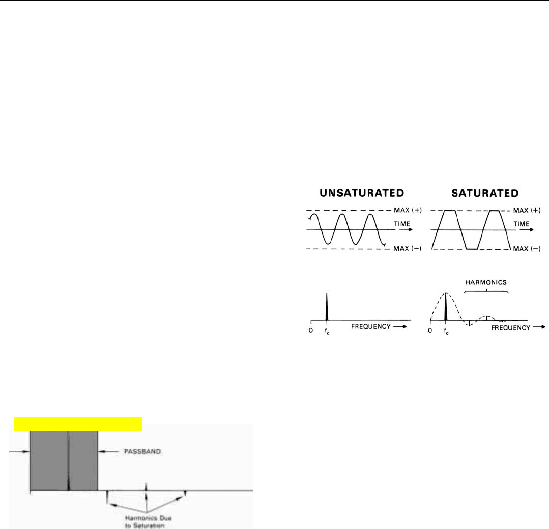
Source of the Spurious Signals. The spurious signals are
of two types: harmonics and cross modulation products.
Harmonics are signals whose frequencies are multiples of
another signal’s frequency. That harmonics are created when
a system’s output is limited by saturation can be demon-
strated simply by lopping off the top and bottom of a sine
wave (Fig. 30).
The result is a nearly square wave. As we saw in Chap.
17, such a wave is made up of a series of sine waves whose
frequencies are multiples of the frequency of the square
wave.
If a system’s passband is narrow enough, the harmonics
may lie outside the passband and so be rejected (Fig. 31).
Otherwise, they may cause problems.
Cross modulation is the modulation of one signal by
another. It is produced if the sum of two or more signals of
different frequency is limited by saturation. The products
of cross modulation are sidebands. They, of course, occur
both above and below the frequencies of the modulated
signals.
Consequently, if the frequencies of the saturating signals
are closely spaced, a great many cross modulation products
will be passed by a system regardless of the width of its
passband.
CHAPTER 18 Sensing Doppler Frequencies
249
30. Harmonics are created when a signal’s peak amplitude is lim-
ited by saturation.
31. If passband is narrow enough, harmonics due to saturation
may be eliminated.
Click for high-quality image
7. For a triangular wave shape,
the rms value is approximate-
ly (1 +
12
) x LSD.
33.
Ideally, you would like the quantization noise to be one-tenth or
less of the system noise, and the saturation limit to be sufficiently
far above the system noise to accommodate the strong signals.
PART IV Pulse Doppler Radar
250
Avoiding Saturation. The creation of harmonics and
cross modulation products may be avoided simply by
avoiding saturation.
Toward this end, in designing a signal processing system,
the average signal level is usually kept as low as possible
without risking the loss of weak signals in the locally gener-
ated noise. Enough dynamic range is then provided to pre-
vent strong signals from saturating the system. Generally,
this approach leads to a tradeoff between saturation, on the
one hand, and low-level noise on the other.
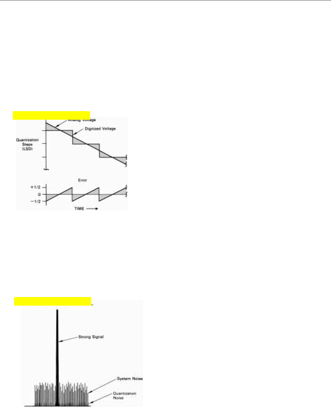
Dealing with Quantization Noise. If the signal processor
is digital, the problem of low-level noise is exacerbated by
the presence of so-called quantization noise. It is the
inevitable result of representing signal amplitudes which
are continuously variable, with digital numbers which are
graduated in finite steps—quanta.
The effect is illustrated for a linearly changing signal in
Fig. 32. After being digitized, the signal actually consists of
the sum of two signals: (1) a quantized replica of the origi-
nal analog signal and (2) a triangular error wave having a
peak amplitude equal to half the value of the least signifi-
cant digit (LSD).
If the original signal is comprised of periodic samples of
the return from a given range, a simple triangular error
wave is generally not produced. For successive samples are
about as likely to fall at one point as another between the
steps of the A/D converter’s reference voltage. Consequently,
this undesirable byproduct of digitization is more or less
random and so is customarily categorized as noise.
Quantization noise in both the A/D converter and the
processor puts a lower limit on the signal levels that can be
handled by a system. A common figure of merit for an A/D’s
dynamic range is the ratio of (1) the maximum peak signal
voltage the A/D can handle to (2) the rms value of the
quantization error voltage.
7
To avoid degrading signal-to-noise ratios, you would like
the quantization noise to contribute only negligibly to the
overall system noise. For that, the level of the incoming sig-
nals must be set high enough that the level of the noise
accompanying the signals is substantially higher than the
quantization noise—ideally, on the order of 10 times higher
(Fig. 33).
To prevent saturation by strong signals, then, the dynam-
ic range must be correspondingly increased. This may
require increasing the number of digits in the numbers
used to represent the signals or handling the processing in a
more clever way or both.
32. If a gradually changing voltage is represented by digital num-
bers, the error due to quantization has a triangular shape and
a peak amplitude equal to half the value of the least signifi-
cant digit (LSD).
Click for high-quality image
Click for high-quality image

Summary
To sort out the radar return from various objects accord-
ing to doppler frequency, the receiver output is applied to a
bank of narrowband filters. If sorting by range is also
desired, a separate bank is provided for each range incre-
ment. The width of the passband of a narrowband filter is
primarily determined by the filter’s integration time but is
increased by losses. So that return will not be lost when a
target straddles two filters, the passbands are made to over-
lap. So that only one line of a target’s spectrum will fall
within the band of frequencies bracketed by the bank, the
passband of the bank is made no greater than the PRF.
The filters may be either analog or digital. For analog fil-
tering, the radar return is translated to a relatively low
intermediate radio frequency. Each filter typically uses one
or more quartz crystals. Its response to an incoming signal
is analogous to that of a pendulum’s response to a succes-
sion of impulses.
For digital filtering, the IF output of the receiver is trans-
lated to video frequencies by applying it to a pair of syn-
chronous detectors, along with a reference signal whose fre-
quency corresponds to that of the transmitter. The outputs
of the detectors represent the in-phase (I) and quadrature
(Q) components of the return. Quadrature components are
needed to preserve the sense of the doppler frequencies.
The outputs of the synchronous detectors are sampled at
a precisely controlled rate. In a pulsed radar, sampling cor-
responds to the range gating of an analog processor. The
sampling rate equals the PRF times the number of range
gates desired.
Each sample is converted to a binary number by com-
paring its voltage with a succession of progressively higher
voltages of precisely known value. The numbers are then
supplied to a special purpose computer, which implements
the filters.
In the case of both analog and digital filters, targets may
be detected automatically by applying the filter outputs to
threshold detectors.
CHAPTER 18 Sensing Doppler Frequencies
251

253
How Digital Filters Work
I
n the preceding chapter we saw how, for digital filtering,
the radar returns are translated to video frequencies by a
pair of synchronous detectors and sampled at precisely
timed intervals. And we learned how the samples are
converted to digital numbers. We were told that the numbers
are then supplied to a computer (signal processor), which
“forms” a separate bank of doppler filters for each sampling
interval (range gate).
1
But little was said about the way in
which the filters are formed.
In this chapter, we will learn how that is done. After briefly
reviewing what the stream of numbers supplied to the com-
puter represents, we will derive the simple set of equations
(algorithm) which the filter must repeatedly compute to form
a filter—the discrete Fourier transform—and see how the
required mathematical operations may be organized. Finally,
we will briefly consider what can be done to reduce the side-
lobes which invariably occur on either side of a filter’s pass-
band.
The organization of a complete filter bank and the inge-
nious approach taken to minimizing the otherwise staggering
computing load (the fast Fourier transform) are covered in the
next chapter.
Inputs to the Filter
Before delving into the details of the digital filter’s opera-
tion, it will be well to have a good physical picture of what the
digitized samples that are the inputs to the filter actually rep-
resent. We can gain a picture of this sort quite easily by view-
ing the output of one of a pulsed radar’s two synchronous
detectors on a range trace.
1. Depending on the radar’s
PRF, the returns passed by
any one range gate may all
come from the same range
increment or they may come
from many ambiguous range
increments separated by R
u
.
PART IV Pulse Doppler Radar
254
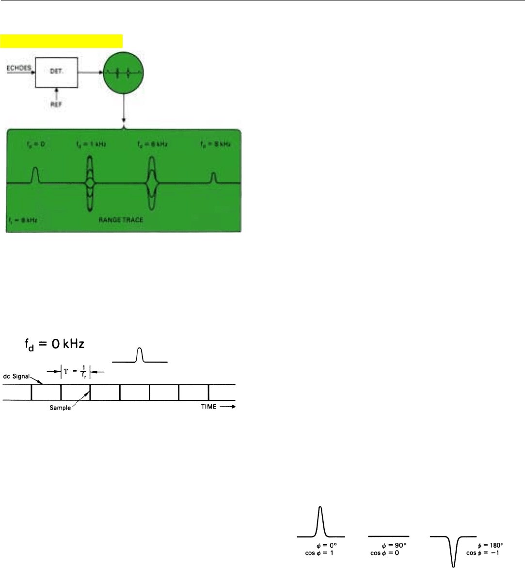
Detector Output Displayed on a Range Trace. Let us
suppose that the output of the in-phase (I) detector is sup-
plied to the vertical deflection circuit of an oscilloscope on
which is displayed a horizontal range trace. The I output,
you’ll recall, equals A cos φ, where A is the amplitude and φ
is the radio-frequency phase of the target return relative to
the reference signal supplied to the detector. The radar’s
PRF, we’ll say, is 8 kilohertz. Echoes are being received from
four targets. Their doppler frequencies are 0, 1, 6, and 8
kilohertz. So that we can isolate the echoes of each target
on the range trace, the targets have been positioned at pro-
gressively greater ranges (Fig. 1). To isolate the effects of the
frequency differences, we will assume that the amplitudes
of the received echoes are all the same.
Despite this similarity, the “pips” which the four targets
produce are all quite different. Not only do they vary in
height, but some fluctuate and others do not. To appreciate
why this is so, you must bear in mind that the height of a
target pip drawn on the oscilloscope during any one range
sweep (interpulse period) corresponds to the detector out-
put produced by a single target echo. Since in this case the
period of even the highest doppler frequency is a great deal
longer than the width of a radar pulse, each pip is essential-
ly a sample taken at a single point in a cycle of the target’s
doppler frequency.
For the target having zero doppler frequency, the height
of successive pips is constant (Fig. 2). The reason is fairly
obvious. Since the target echoes have the same frequency as
the reference signal, their phase, relative to it, does not
change from one echo to the next. The detector output for
the range increment in which this target resides is a pulsed
dc voltage. As was explained in the last chapter, the ampli-
tude of this voltage may lie anywhere between zero and
plus or minus A, depending upon the phase (φ) of the tar-
get echoes (Fig. 3).
1. Output of a single-channel synchronous detector displayed on
a range trace. Echoes of equal amplitude are being received
from four targets having different doppler frequencies.
2. Detector output for target with zero doppler frequency has
constant amplitude.
3. Depending on the echo’s radio frequency phase, the amplitude of
detector output for zero doppler frequency may be anywhere
between +1 and –1 times echo’s amplitude.
One of the reasons for providing both I and Q channels,
of course, is to eliminate this variability. Since the output of
the I detector equals A cos φ and the output of the Q detec-
tor equals A sin φ, the magnitude of the vector sum of the
two outputs for all values of φ equals A.
Click for high-quality image