George W. Stimson introduction to Airborne Radar (Se)
Подождите немного. Документ загружается.

12. If PRF is less than spread of maximum closing rates, radar has
no direct way of telling which repetition of carrier frequency it
is observing.
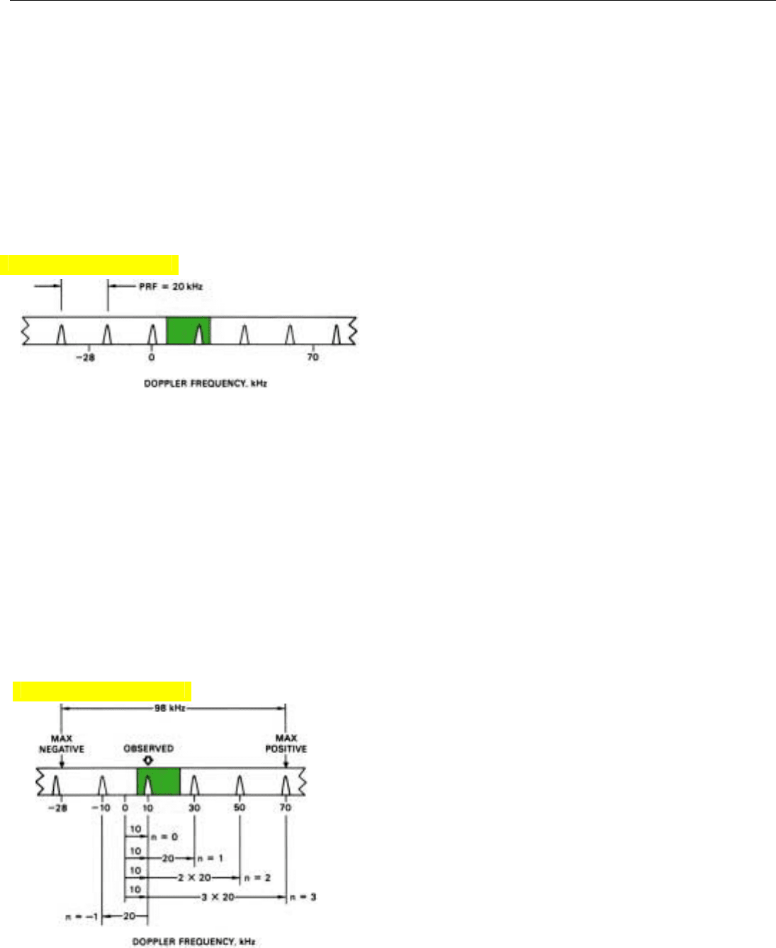
13. If PRF is 20 kilohertz and observed doppler frequency is 10
kilohertz, true doppler could have any of these values: –10,
10, 30, 50, and 70 kilohertz.
PART IV Pulse Doppler Radar
286
Thus, if the PRF is greater than the spread between the
maximum anticipated positive and negative doppler fre-
quencies, the only spectral line of the target echoes produc-
ing an output from the filter bank will be the central line—
the carrier. The difference between its frequency and the
transmitter’s carrier frequency is the target’s true doppler
frequency. Hence, no significant ambiguities will exist.
This would not be so, however, if the PRF were less than
the spread between the maximum positive and negative
doppler frequencies—as it often must be to satisfy other
operational requirements.
PRF Less Than Spread of Doppler Frequencies. Suppose
that in this same hypothetical situation—difference
between maximum anticipated positive and negative
doppler frequencies equals 98 kilohertz—we reduce the
PRF to only 20 kilohertz (Fig. 12). The separation between
a target echoes’ carrier frequency and first pair of side-
bands, as well as between successive sidebands above and
below them, is now only one-sixth of what is was before.
So that the return from any one target will appear at only
one point within the passband, we must make it somewhat
less than 20 kilohertz wide. But if the sidebands are only 20
kilohertz apart, no matter where we position the passband,
there is no direct way of telling whether the target return
that appears in the bank is the echoes’ carrier or a sideband,
or, which sideband it might be. To determine the target’s
true doppler frequency—hence its range rate—we must
resolve the ambiguity.
Resolving Doppler Ambiguities
To resolve doppler ambiguities, we must have some way
of telling what whole multiple of the PRF, if any, separates
the observed frequency of the target echoes from the carrier
frequency. If not too great, this multiple—n—may readily
be determined. There are two common ways: range differ-
entiation and PRF switching.
Range Differentiation. Generally, the simplest way to
determine the value of n is to make an approximate initial
measurement of the range rate by the differentiation
method. From this rate, we compute the approximate value
of the true doppler frequency. Subtracting the observed fre-
quency from the computed value of the true frequency and
dividing by the PRF yields the factor n.
Suppose, for example, that the PRF is 20 kilohertz and
the observed doppler frequency is 10 kilohertz (Fig. 13).
The true doppler frequency then could be –10 kilohertz
plus any whole multiple of 20 kilohertz up to 70 kilohertz.
The approximate value of the true doppler frequency com-
puted from the initial range rate measurement, let’s say,
Click for high-quality image
Click for high-quality image
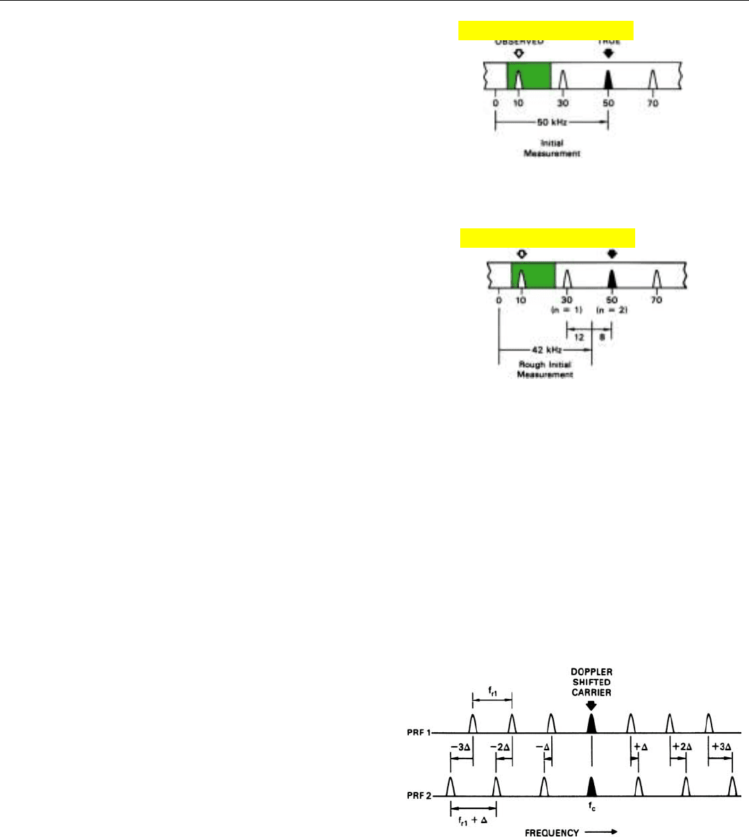
turns out to be 50 kilohertz. The difference between this
frequency and the observed doppler frequency is 50 – 10 =
40 kHz. Dividing the difference by the PRF, we get n = 40 ÷
20 = 2 (Fig. 14). The echoes’ carrier is separated from the
observed doppler frequency by two times the PRF.
Although in this simple example we assumed that the
initial range-rate measurement was fairly precise, it need
not be particularly accurate. As long as any error in the
doppler frequency computed from the initial rate measure-
ment is less than half the PRF, we can still tell in which PRF
interval the carrier lies and so tell what n is. The initially
computed “true” doppler frequency, for example, might
have been only 42 kilohertz, almost half way between the
two nearest possible exact values (30 and 50 kilohertz)
(Fig. 15).
Nevertheless, this rough initially computed value (42
kilohertz) would still be accurate enough to enable us to
find the correct value of n. The difference between the ini-
tially computed value of the doppler frequency and the
observed value is 42 – 10 = 32 kHz. Dividing the difference
by the PRF, we get 32 ÷ 20 = 1.6. Rounding off to the near-
est whole number, we still come up with n = 2.
After having determined the value of n just this once, we
can, by tracking the target continuously, determine the true
doppler frequency, hence compute R
⋅
with considerable pre-
cision, solely on the basis of the observed frequency.
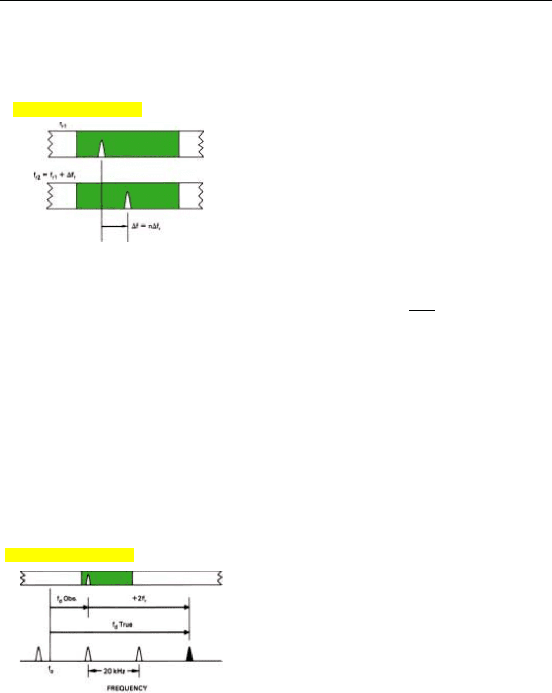
PRF Switching. The value of n can also be determined
with a PRF switching technique similar to that used to
resolve range ambiguities (see Chap. 12). In essence, this
technique involves alternately switching the PRF between
two relatively closely spaced values and noting the change,
if any, in the target’s observed frequency.
Naturally, switching the PRF will have no effect on the
target echoes’ carrier frequency f
c
. It, of course, equals the
carrier frequency of the transmitted pulses plus the target’s
doppler frequency and is completely independent of the
PRF. But not the sideband frequencies above and below f
c
.
Because these frequencies are separated from f
c
by multiples
of the PRF, when we change the PRF, the sideband frequen-
cies correspondingly change (Fig. 16).
Which direction a particular sideband frequency
moves—up or down—depends upon two things: (1)
whether the sideband frequency is above or below f
c
and
(2) whether the PRF has been increased or decreased. An
upper sideband will move up if the PRF is increased and
down if it is decreased. A lower sideband, on the other
hand, will move down if the PRF is increased and up if it is
decreased.
CHAPTER 21 Measuring Range Rate
287
14. By making initial measurement of R
⋅
with differentiation
method, true doppler frequency, hence value of n, can be
immediately determined.
15. Initial measurement of true doppler frequency need not be par-
ticularly accurate. If error is less than half the PRF, value of n
can still be found.
16. If PRF is changed, each sideband frequency shifts by amount,
n∆, proportional to multiple of f
r
separating it from carrier.
Click for high-quality image
Click for high-quality image
17. By noting the change in observed frequency when PRF is
switched, multiple (n) of f
r
contained in true frequency can be
determined.
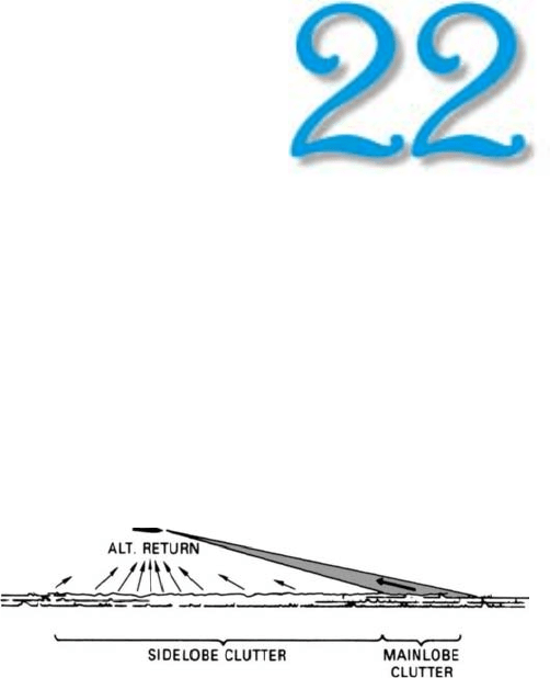
18. True doppler frequency is computed by adding n times f
r
to
observed doppler frequencies. (Here n = 2.)
PART IV Pulse Doppler Radar
288
How much the observed doppler frequency moves also
depends upon two things: (1) how much the PRF has been
changed and (2) what multiple of the PRF separates the
observed frequency from f
c
. If the PRF is changed by 1 kilo-
hertz, the first set of sidebands on either side of f
c
will move
1 kilohertz; the second, 2 kilohertz; the third, 3 kilohertz,
and so on. If the PRF is changed by 2 kilohertz, each set of
sidebands will move twice as far, and so on.
By noting the change, if any, in the target’s observed
doppler frequency, we can immediately tell where f
c
is rela-
tive to the observed frequency (Fig. 17). If the observed fre-
quency does not change, we know that it is f
c
. If it does
change, we can tell from the direction of the change
whether f
c
is above or below the observed frequency. And
we can tell from the amount of the change by what multiple
of the PRF f
c
is removed from the observed frequency.
Thus, the factor n by which the PRF must be multiplied
to obtain the difference between the echoes’ carrier fre-
quency f
c
and the observed frequency is
n =
∆f
obs
∆f
r
where
∆f
obs
= change in target’s observed frequency
when PRF is switched
∆f
r
= amount PRF is changed
If, for example, an increase in PRF (∆f
r
) of 2 kilohertz
caused a target’s observed doppler frequency to increase by
4 kilohertz, the value of n would be 4 ÷ 2 = 2.
In order to avoid the possibility of “ghosts” when returns
are simultaneously received from more than one target, the
PRF must generally be switched from one to another of
three values, instead of two, just as when resolving range
ambiguities. As explained in Chap. 12, switching the PRF
has the disadvantage of reducing the maximum detection
range.
Calculating the Doppler Frequency. Having determined
the value of n by either of the methods just outlined, we
can compute the target’s true doppler frequency, f
d
, simply
by multiplying the PRF by n and adding the product to the
observed frequency (Fig. 18)
f
d
= n f
r
+ f
obs
where
f
r
= PRF before the switch
f
obs
= target’s observed doppler frequency
Click for high-quality image
Click for high-quality image

Summary
A target’s range rate may be determined either by contin-
uously measuring its range and calculating the rate at
which the range changes—a process that approximates dif-
ferentiation—or by measuring the target’s doppler frequen-
cy. Because of inevitable random errors in the measured
range, the differentiation method tends to be less accurate
and provides poorer dynamic response.
The doppler method not only can be extremely precise,
but can be nearly instantaneous. The observed doppler fre-
quencies, however, are inherently ambiguous. Unless the
spread between the maximum anticipated positive and neg-
ative doppler frequencies is less than the PRF—and the
consequence of occasionally mistaking a very high-speed
target for a lower speed one is negligible—the ambiguities
must be resolved.
To resolve them, the number of times, n, that the PRF is
contained in the difference between the observed frequency
and the true frequency must be determined. If n is not too
large, it can readily be found either by measuring the range
rate initially with the differentiation method or by switch-
ing the PRF and observing the direction and amount that
the observed doppler frequency changes.
CHAPTER 21 Measuring Range Rate
289
293
Sources and Spectra
of Ground Return
G
round return falls into three categories: main-
lobe return, sidelobe return, and altitude
return, which is sidelobe return received from
directly beneath the radar. Mainlobe return is
signal for many applications—ground mapping, altimetry,
doppler navigation, etc. But both mainlobe and sidelobe
return are clutter for radars which must detect airborne
targets or moving targets on the ground (Fig. 1).
The principal means of discerning target echoes from
ground clutter is doppler resolution. In ground based
applications, separating targets from clutter is straightfor-
ward. Since the radar is stationary, all of the clutter has
essentially one doppler frequency—zero. In airborne
applications, however, this is far from true. Consequently,
the way in which the clutter is distributed over the band of
possible frequencies—its doppler spectrum—and the rela-
tionship of this spectrum to the doppler frequencies of
anticipated targets critically influence a radar’s design.
In this chapter, we’ll consider what determines the
amplitude of the ground return. We will then examine the
doppler spectrum of each of the three categories of ground
return, and the relationship of the composite spectrum to
the doppler frequencies of target aircraft in representative
situations. Finally, we’ll consider the problem of exception-
ally strong sidelobe return reflected by certain objects on
the ground.
For simplicity, we will assume that the radar is transmit-
ting at a sufficiently high PRF that doppler ambiguities are
avoided. Their effect—which can make ground clutter
much more difficult to deal with—will be covered in the
next chapter.
1. The three categories of ground clutter.
PART V Return from the Ground
294
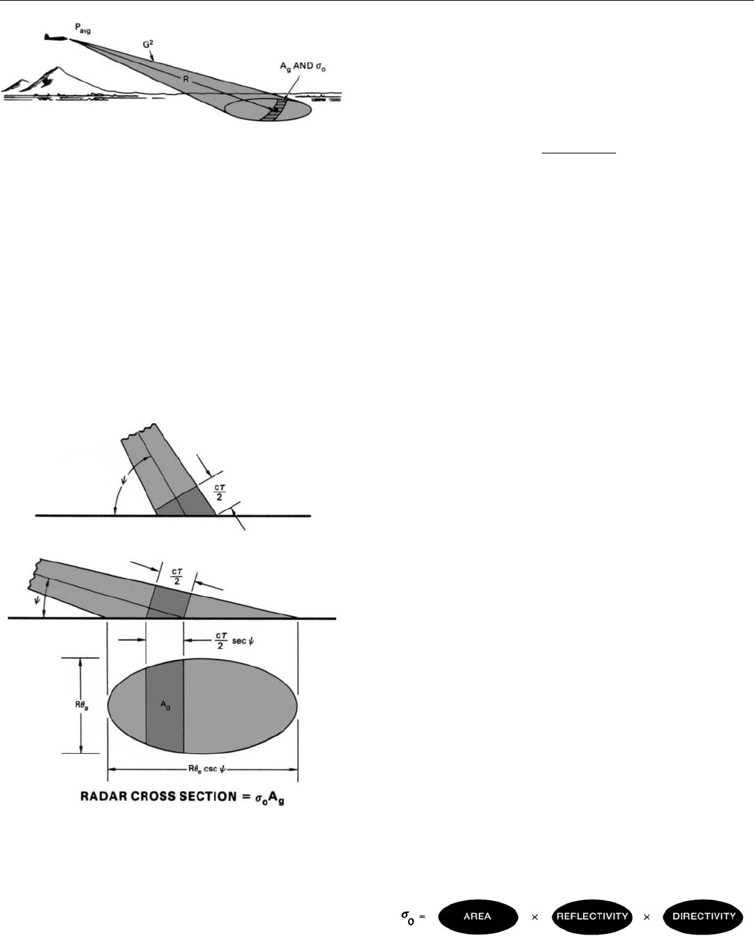
What Determines the Amplitude of the Ground Return
In general, ground return is governed by the same basic
factors as return from an aircraft. For a given transmitter
frequency, the power of the return received from a small
patch of ground (Fig. 2) is
P
r
∝
P
avg
G
2
σ
o
A
g
R
4
where
P
avg
= average transmitted power
G = gain of radar antenna in the direction of
the patch (G
2
= two-way gain)
σ
o
= factor called the incremental backscattering
coefficient
A
g
= resolvable area of ground (ground patch)
R = range of ground patch
The backscattering coefficient,
σ
o
, is the radar cross section
of a small increment of ground area, ∆A.
There are three reasons for using an incremental coeffi-
cient. First, the ground viewed by a radar is more or less
continuous. Second, the extent to which a given radar iso-
lates the return from any one portion of the total ground
area depends upon the radar’s design—antenna beamwidth,
etc. (In contrast, the radar cross section of a discrete target,
such as an aircraft, is independent of the radar’s design.)
Third, the backscattering coefficient may vary considerably
from one increment of ground to the next. As a rule,
though, statistical averages of the coefficient are used for
different types of terrain.
When the appropriate values of
σ
o
is multiplied by the
area of a particular patch of ground—say the area at a spe-
cific azimuth and elevation that is delineated by a radar’s
range, angle, and doppler resolution—the product is the
radar cross section (
σ
) of the patch (Fig. 3).
Like the radar cross section of a discrete target,
σ
o
is the
product of three factors:
• Geometric area
• Reflectivity
• Directivity
2. Factors which determine the power of the return from a patch
of ground: two-way gain of the radar antenna, range to the
patch, area of the patch, and backscattering coefficient,
σ
o
.
3. Radar cross section of a patch of ground equals backscattering
coefficient,
σ
o
, times resolvable ground area, A
g
. Depending
on pulse width,
τ
, at steep grazing angles (
ψ
), A
g
may be
determined solely by a radar’s doppler and angular resolution
and
ψ
. Generally, at shallow angles A
g
also is limited by
τ
.
4. Factors of which the incremental backscattering coefficient,
σ
,
is a product.
Reflectivity is the ratio of scattered energy to intercepted
energy. It varies widely with the conductivity and dielectric
constant of the ground, as well as with the nature of the
objects on it.
The directivity of an incremental ground area, like the
directivity of a discrete target, is the ratio of (a) the energy
scattered back toward the radar to (b) the energy that would
have been backscattered if the scattering had been isotropic.
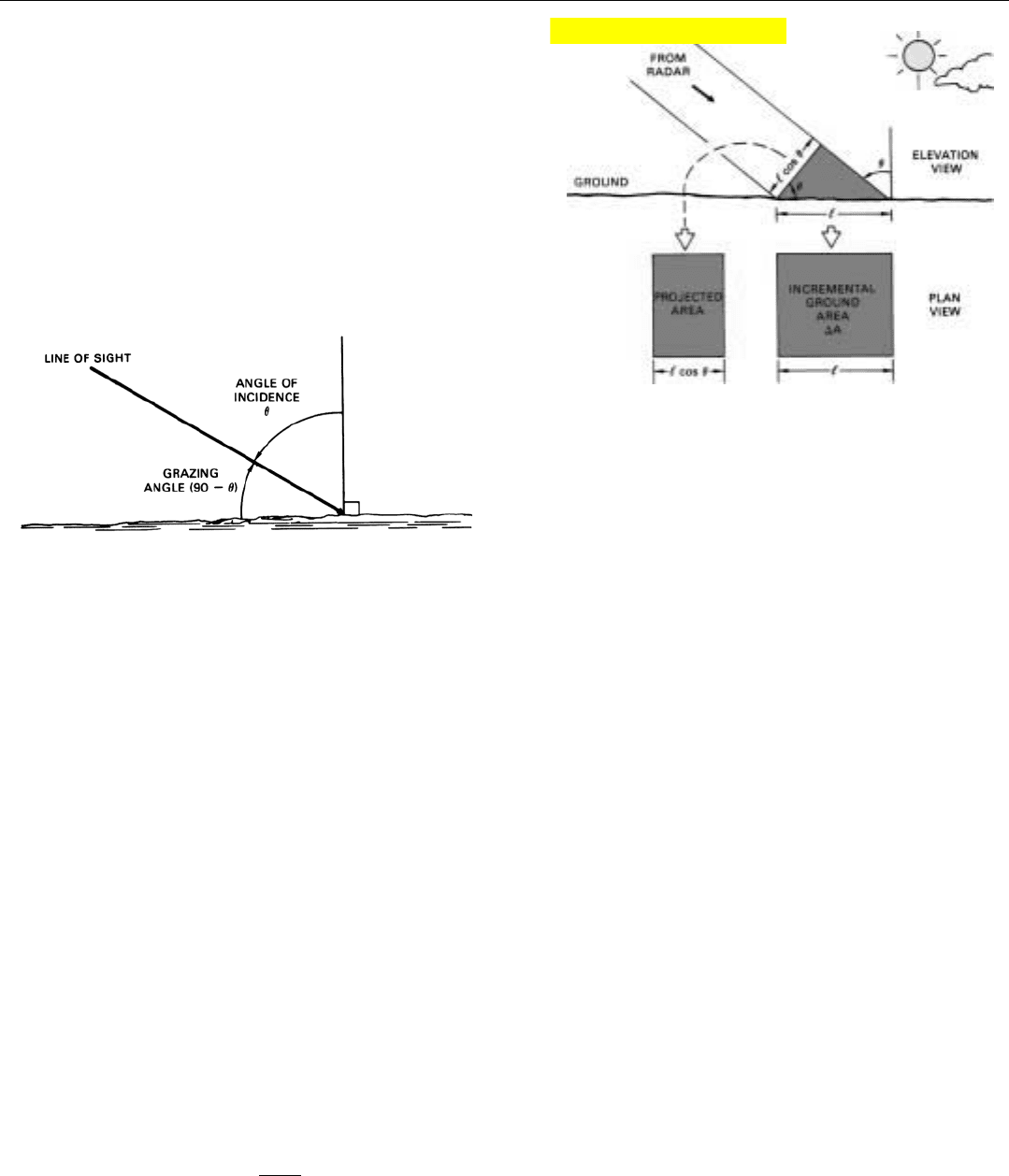
This ratio depends in a complex way upon the angle of inci-
dence (
θ
, in Fig. 5), the roughness of the surface relative to
the wavelength of the incident radio waves, the polarization
of the waves, the presence of man-made objects, etc.
Since the purely geometrical relationship between angle
of incidence and
σ
o
has nothing to do with the nature of the
ground, analysis may sometimes be simplified by math-
ematically cancelling it out. To do so, one merely divides
σ
o
by cos
θ
. The resulting coefficient, called the normalized
backscattering coefficient, is represented by the Greek letter,
gamma, γ.
1
γ =
σ
o
cos
θ
Any variation in the value of γ with the angle of incidence is
due solely to variations in reflectivity and directivity. Over
most angles of incidence, though, γ is more or less constant,
and that is why it is used.
Geometric area is the projection of the incremental area,
∆A, onto a plane perpendicular to the line of sight from the
radar (Fig. 5). This projection determines how much trans-
mitted energy will be intercepted by ∆A. (The power of the
intercepted radiation equals the power density of the inci-
dent waves times the projected area.) The depth (vertical
dimension) of the projected area is foreshortened in pro-
portion to the cosine of the angle of incidence,
θ
. Con-
sequently,
σ
o
decreases as the angle of incidence increases.
Put another way, as the grazing angle (Fig. 6) approaches
zero, so does the value of
σ
o
.
CHAPTER 22 Sources and Spectra of Ground Return
295
5. The term for area included in the backscattering coefficient
σ
o
, is the projection of the incremental area, ∆A, onto a plane
perpendicular to the line of sight to the radar.
6. As the angle of incidence,
θ
, approaches 90° (the grazing
angle approaches 0
°), the projection of ∆A onto a plane
normal to the line of sight to radar goes to zero.
1. The normalized coefficient
is also represented by the
Greek letter eta (η).
Click for high-quality image
PART V Return from the Ground
296
Backscattering coefficients are normally expressed in dB.
The greater the fraction of the incident energy scattered
back in the direction of the radar is, the greater (less nega-
tive) the coefficient. Where the gain due to directivity is
high—as, for example, at small angles of incidence over
water—the decibel value of
σ
o
becomes positive.
Table 1 lists the values of both
σ
o
and γ for common
types of terrain at comparatively shallow grazing angles
(large angles of incidence). When operating over smooth
water, little or no energy is reflected back to the radar from
such angles. Over desert, the return is substantially greater.
Over wooded areas with a liberal sprinkling of man-made
structures, it is greater still. Over cities, it is even greater.
Mainlobe Return
Mainlobe return—or mainlobe clutter (MLC) as it is called
when it is not desired—is produced whenever the mainlobe
intercepts the ground, as when looking down or flying at
low altitudes and not looking up. It may be received from
long ranges, even when flying at high altitudes and looking
straight ahead.
Because the ground area intercepted by the mainlobe can
be extensive and the gain of the mainlobe is high, mainlobe
return is generally quite strong—far stronger than the
return from any aircraft.
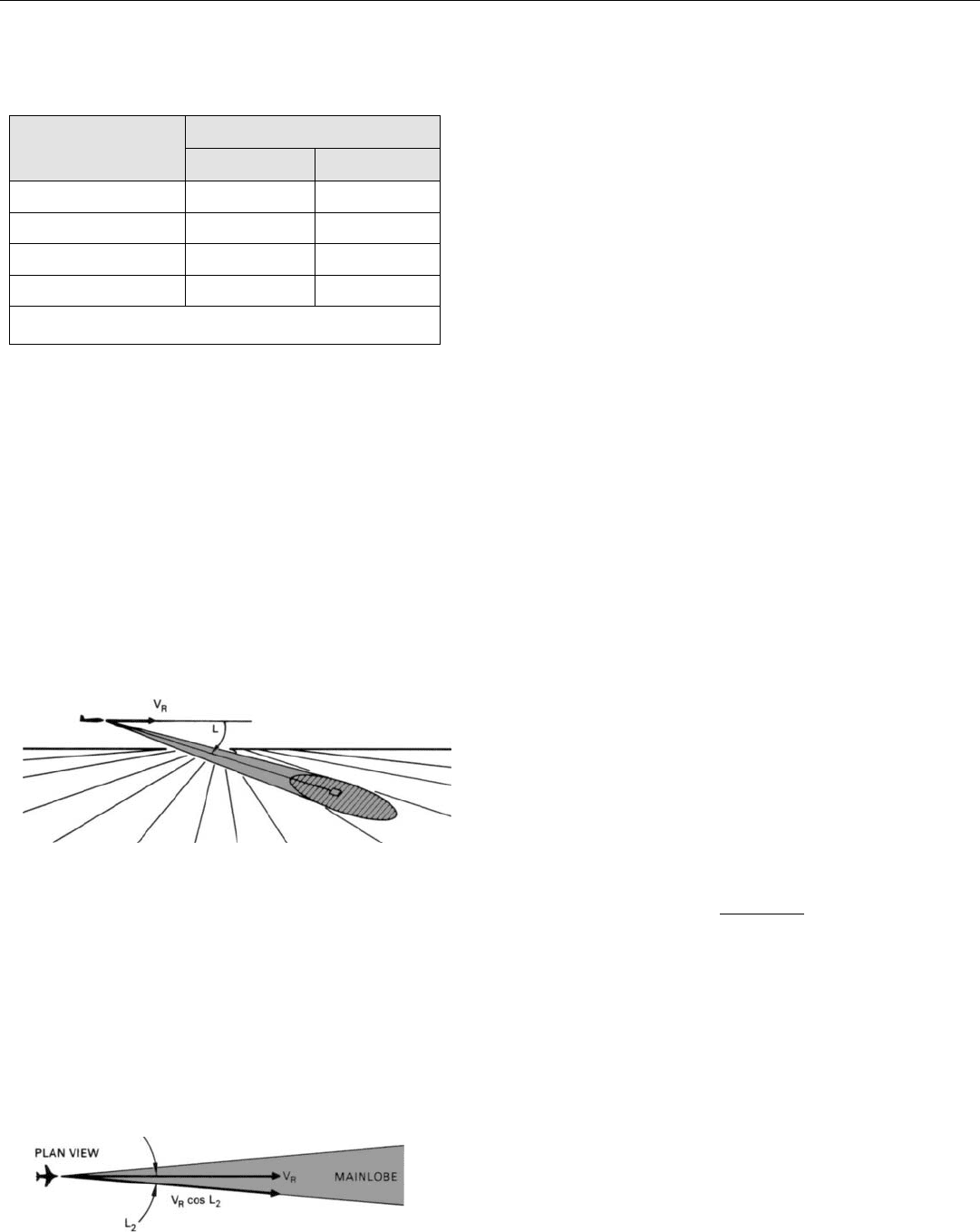
Frequency Versus Angle. The spectral characteristics of
mainlobe return are best understood by visualizing the
ground area illuminated by the mainlobe as consisting of a
large number of small, individual patches (Fig. 7). The
doppler frequency of each patch is proportional to the
cosine of the angle, L, between the radar velocity and the
line of sight to the patch.
f
d
=
2 V
R
cos L
λ
where
V
R
= velocity of radar
L = angle between V
R
and line of sight to
ground patch
λ = wavelength
The angle L is not the same for every patch. As a result, the
collective return occupies a band of frequencies.
When the antenna is looking straight ahead (Fig. 8), the
doppler frequency of the return from patches near the cen-
ter of the illuminated area (L ≈ 0) very nearly equals its
maximum possible value: f
d
max
= 2 V
R
/λ.
7. Area illuminated by mainlobe may be thought of consisting of
many small ground patches, each at a different look angle.
8. When looking straight ahead, closing rate for all look angles
within the beam is about the same, and f
d
≈ 2V
R
/λ.
TYPICAL BACKSCATTERING COEFFICIENTS
Coefficients (dB)*
o
Smooth Water – 53 – 45.4
Desert – 20 – 12.4
Wooded Area – 15 – 7.4
Cities – 7 0.6
*Values for a 10° grazing angle and 10 GHz frequency.
σ
γ
Terrain
The frequencies of those patches farther from the center
are somewhat lower. But, since the angles to these patches
are small and the cosine of a small angle is very nearly one,
the band of frequencies covered by the mainlobe return
when looking straight ahead is quite narrow.
As the azimuth and depression angles of the antenna
increase, the cosine of L for patches at the center of the illu-
minated ground area decreases (Fig. 9). Consequently, the
frequency of these patches decreases. At the same time, the
spread between the values of cos L for patches at the two
edges of the area increases, causing the band of frequencies
covered by the mainlobe clutter to become wider.
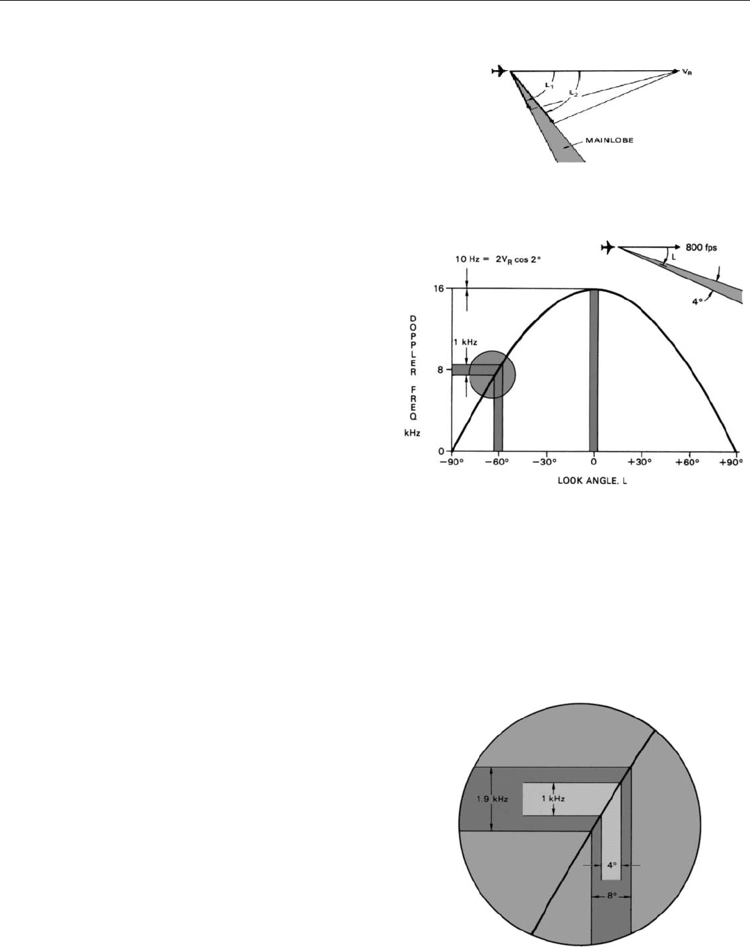
To give you a quantitative feel for these relationships, the
cosine of the angle L off the center of the illuminated area is
plotted in Fig. 10 for values of L between ± 90°. The verti-
cal scale gives the corresponding doppler frequencies for a
radar velocity of 800 feet per second (approximately 480
knots) and a wavelength of 0.1 foot (3 centimeters).
Superimposed over the graph are two vertical bands.
Each brackets those angles encompassed by a mainlobe
having a beamwidth of 4°. The band in the center is for an
antenna azimuth angle of zero. The other band is for an
antenna azimuth angle of 60°. (In both cases, the antenna
depression angle is zero, and the aircraft is assumed to be at
very low altitude.)
When the azimuth is 0°, the central doppler frequency
of the return is 16 kilohertz. Yet, when the azimuth has
increased to 60°, this frequency is only 8 kilohertz—a
decrease of 50 percent (cos 60° = 0.5).
The width of the band of frequencies spanned by the
return, on the other hand, is vastly greater at the larger
antenna angle. When the azimuth is 0°, the doppler fre-
quency of a patch at the edge of the illuminated ground
area (f
d
max
cos 2°) is so close to that of a patch at the center
(f
d
max
) that the difference cannot be read from the graph.
Actually, it is about 10 hertz. Yet (since the cosine changes
much more rapidly with angle at large angles), when the
azimuth is 60°, the return spans a band of frequencies near-
ly 1 kilohertz wide—f
d
max
(cos 58° – cos 62°) = 16 (0.53
– 0.47) = 0.96 kilohertz.
Influence of Beamwidth, Speed, and Wavelength. For
any one antenna azimuth (and/or depression) angle, the
wider the mainlobe, the wider the band of mainlobe fre-
quencies will be (Fig. 11). If the beamwidth were
increased from 4° to 8°, the width of the band for an
antenna angle of 60° would be 1.9 kilohertz—nearly
twice that for the 4° beam.
Both the center frequency and the width of the band
vary directly with the speed of the radar (f
d
max
∝ V
R
). If it
CHAPTER 22 Sources and Spectra of Ground Return
297
9. As angle L increases, value of cos L for patches at center of
beam decreases, and spread between values for patches at
edges of beam increases.
10. Variation in doppler frequency of mainlobe clutter with look
angle. Vertical bands represent width of lobe (λ = 0.1 foot).
11. The wider the mainlobe, the wider the band of mainlobe clutter
frequencies.
PART V Return from the Ground
298
decreases, they decrease; if it increases, they increase.
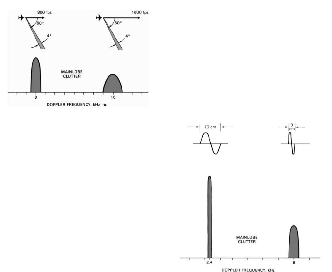
Suppose the center frequency is, say, 8 kilohertz. If the
speed were doubled, this frequency as well as the frequen-
cies at the edges of the band would double. Not only would
the entire band shift up by 8 kilohertz, but its width would
double (Fig. 12).
The width and center frequency vary inversely with
wavelength (f
d
max
∝ 1/λ). The longer the wavelength, the
narrower the band will be, and vice versa. Other conditions
being the same, at S-band wavelengths (10 centimeters),
the band is only three-tenths as wide as at X-band wave-
lengths (3 centimeters) (Fig. 13).
13. If the wavelength of the radar transmitter is decreased, both
the center frequency and the spectral width of the mainlobe
clutter will increase proportionately.
12. If the speed of the radar is doubled, both the center frequency
and the width of the spectrum will double.
Effect of Antenna Scan. During search, the antenna scans
back and forth through an azimuth angle which may be
±70 or more degrees. As it sweeps from one extreme to
straight ahead (Fig. 14, top of next page), the mainlobe
clutter band moves up in frequency and simultaneously
squeezes into a narrow line. As the sweep continues to the
other extreme, the clutter moves down in frequency and
spreads to its original width. Thus the band appears to
“breathe.”
Significance. Because of its strength, spectral width, and
variability, mainlobe return can be difficult to contend with
when searching for aircraft. On the other hand, the strength
and spectral width are advantageous when ground map-
ping. Then, the stronger the mainlobe return, the better;