Halderman J.D., Linder J. Automotive Fuel and Emissions Control Systems
Подождите немного. Документ загружается.

ENGINE CONDITION DIAGNOSIS 141
STEP 2 Block open the throttle. This permits the maximum
amount of air to be drawn into the engine. This step
also ensures consistent compression test results.
CAUTION: Disable the ignition system by dis-
connecting the primary leads from the ignition
coil or module or by grounding the coil wire after
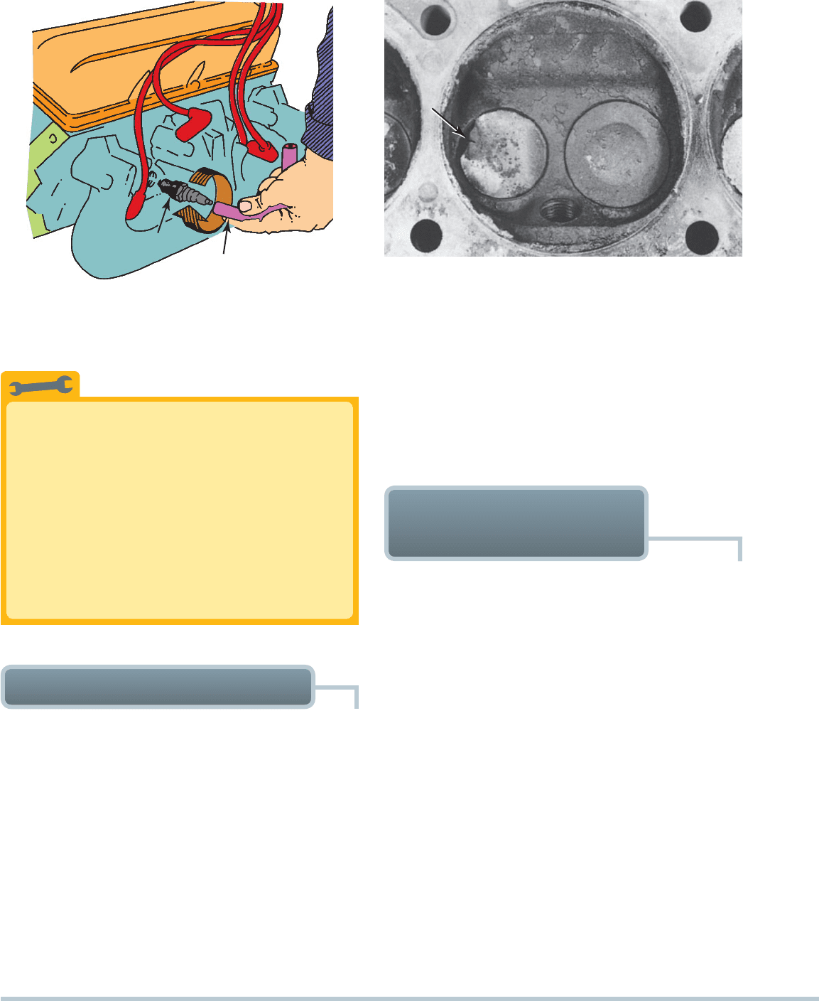
FIGURE 10–10 A two-piece compression gauge set. The
threaded hose is screwed into the spark plug hole after re-
moving the spark plug. The gauge part is then snapped onto
the end of the hose.
TAIL PIPE
PAPER
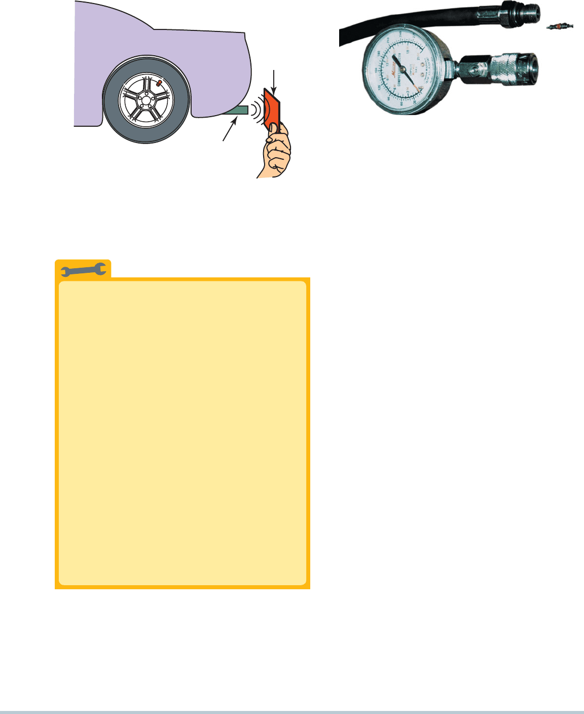
FIGURE 10–9 The paper test involves holding a piece of
paper near the tailpipe of an idling engine. A good engine
should produce even, outward puffs of exhaust. If the paper is
sucked in toward the tailpipe, a burned valve is a possibility.
TECH TIP
The Paper Test
A soundly running engine should produce even and
steady exhaust at the tailpipe. You can test this with
the paper test. Hold a piece of paper or a 3 5
index card (even a dollar bill works) within 1 inch
(25mm) of the tailpipe with the engine running at
idle.
SEE FIGURE 10–9 .
The paper should blow out evenly without
“puffing.” If the paper is drawn toward the tailpipe
attimes, the exhaust valves in one or more cylinders
could be burned. Other reasons why the paper might
be sucked toward the tailpipe include the following:
1. The engine could be misfiring because of a lean
condition that could occur normally when the
engine is cold.
2. Pulsing of the paper toward the tailpipe could
also be caused by a hole in the exhaust system.
If exhaust escapes through a hole in the exhaust
system, air could be drawn in during the intervals
between the exhaust puffs from the tailpipe to
the hole in the exhaust, causing the paper to be
drawn toward the tailpipe.
3. Ignition fault causing misfire.
removing it from the center of the distributor
cap. Also disable the fuel-injection system to
prevent the squirting of fuel into the cylinder.
STEP 3 Thread a compression gauge into one spark plug hole
and crank the engine.
SEE FIGURE 10–10 .
Continue cranking the engine through four com-
pression strokes. Each compression stroke makes a
puffing sound.
NOTE: Note the reading on the compression
gauge after the first puff. This reading should be
at least one-half the final reading. For example,
if the final, highest reading is 150 PSI, then the
reading after the first puff should be higher than
75 PSI. A low first-puff reading indicates pos-
sible weak piston rings. Release the pressure
on the gauge and repeat for the other cylinders.
STEP 4 Record the highest readings and compare the results.
Most vehicle manufacturers specify the minimum
compression reading and the maximum allowable var-
iation among cylinders. Most manufacturers specify
a maximum difference of 20% between the highest
reading and the lowest reading. An example follows:
If the high reading is 150 PSI
Subtract 20% ⫺30 PSI
Lowest allowable compression is 120 PSI
NOTE: To make the math quick and easy, think
of 10% of 150, which is 15 (move the decimal
point to the left one place). Now double it: 15 ⫻
2 ⫽ 30. This represents 20%.
NOTE: During cranking, the oil pump cannot main-
tain normal oil pressure. Extended engine cranking,
such as that which occurs during a compression
test, can cause hydraulic lifters to collapse. When
the engine starts, loud valve clicking noises may
be heard. This should be considered normal af-
ter performing a compression test, and the noise
should stop after the vehicle has been driven a
short distance.
142 CHAPTER 10
SPARK
PLUG
RUBBER
HOSE
FIGURE 10–11 Use a vacuum or fuel line hose over the
spark plug to install it without danger of cross-threading the
cylinder head.
FIGURE 10–12 Badly burned exhaust valve. A compression
test could have detected a problem, and a cylinder leakage
test (leak-down test) could have been used to determine the
exact problem.
The Hose Trick
Installing spark plugs can be made easier by using a
rubber hose on the end of the spark plug. The hose
can be a vacuum hose, fuel line, or even an old spark
plug wire end.
SEE FIGURE 10–11 .
The hose makes it easy to start the threads of
the spark plug into the cylinder head. After starting
thethreads, continue to thread the spark plug for
several turns. Using the hose eliminates the chance of
cross-threading the plug. This is especially important
when installing spark plugs in aluminum cylinder heads.
TECH TIP
If the compression test reading indicates low compression on
one or more cylinders, add three squirts of oil to the cylinder and
retest. This is called a wet compression test when oil is used
to help seal around the piston rings.
CAUTION: Do not use more oil than three squirts from a
hand-operated oil squirt can. Too much oil can cause a
hydrostatic lock, which can damage or break pistons or
connecting rods or even crack a cylinder head.
Perform the compression test again and observe the re-
sults. If the first-puff readings greatly improve and the readings
are much higher than without the oil, the cause of the low com-
pression is worn or defective piston rings. If the compression
WET COMPRESSION TEST
readings increase only slightly (or not at all), then the cause
of the low compression is usually defective valves.
SEE
FIGURE 10–12 .
NOTE: During both the dry and wet compression tests,
be sure that the battery and starting system are capable
of cranking the engine at normal cranking speed.
RUNNING (DYNAMIC)
COMPRESSION TEST
A compression test is commonly used to help determine engine
condition and is usually performed with the engine cranking.
What is the RPM of a cranking engine? An engine idles
at about 600 to 900 RPM, and the starter motor obviously
cannot crank the engine as fast as the engine idles. Most manu-
facturers’ specifications require the engine to crank at 80 to
250 cranking RPM. Therefore, a check of the engine’s compres-
sion at cranking speed determines the condition of an engine
that does not run at such low speeds.
But what should be the compression of a running engine?
Some would think that the compression would be substantially
higher because the valve overlap of the cam is more effective
at higher engine speeds, which would tend to increase the
compression.
A running compression test, also called a dynamic com-
pression test, is a compression test done with the engine run-
ning rather than during engine cranking as is done in a regular
compression test.
Actually, the compression pressure of a running engine is
much lower than cranking compression pressure. This results
from the volumetric efficiency. The engine is revolving faster,
and therefore there is less time for air to enter the combustion
ENGINE CONDITION DIAGNOSIS 143
chamber. With less air to compress, the compression pressure
is lower. Typically, the higher the engine RPM, the lower the
running compression. For most engines, the value ranges are
as follows:
Compression during cranking: 125 to 160 PSI
Compression at idle: 60 to 90 PSI
Compression at 2,000 RPM: 30 to 60 PSI
As with cranking compression, the running compression of
all cylinders should be equal. Therefore, a problem is likely to be
detected not by single compression values but by variations in
running compression values among the cylinders. Broken valve
springs, worn valve guides, bent pushrods, and worn cam lobes
are some items that would be indicated by a low running com-
pression test reading on one or more cylinders.
PERFORMING A RUNNING COMPRESSION TEST To
perform a running compression test, remove just one spark
plug at a time. With one spark plug removed from the engine,
use a jumper wire to ground the spark plug wire to a good
engine ground. This prevents possible ignition coil damage. Start
theengine, push the pressure release on the gauge, and read the
compression. Increase the engine speed to about 2,000 RPM
and push the pressure release on the gauge again. Read the
gauge. Stop the engine, reinstall the spark plug, reattach the
spark plug wire, and repeat the test for each of the remaining
cylinders. Just like the cranking compression test, the running
compression test can inform a technician of the relative com-
pression of all the cylinders.
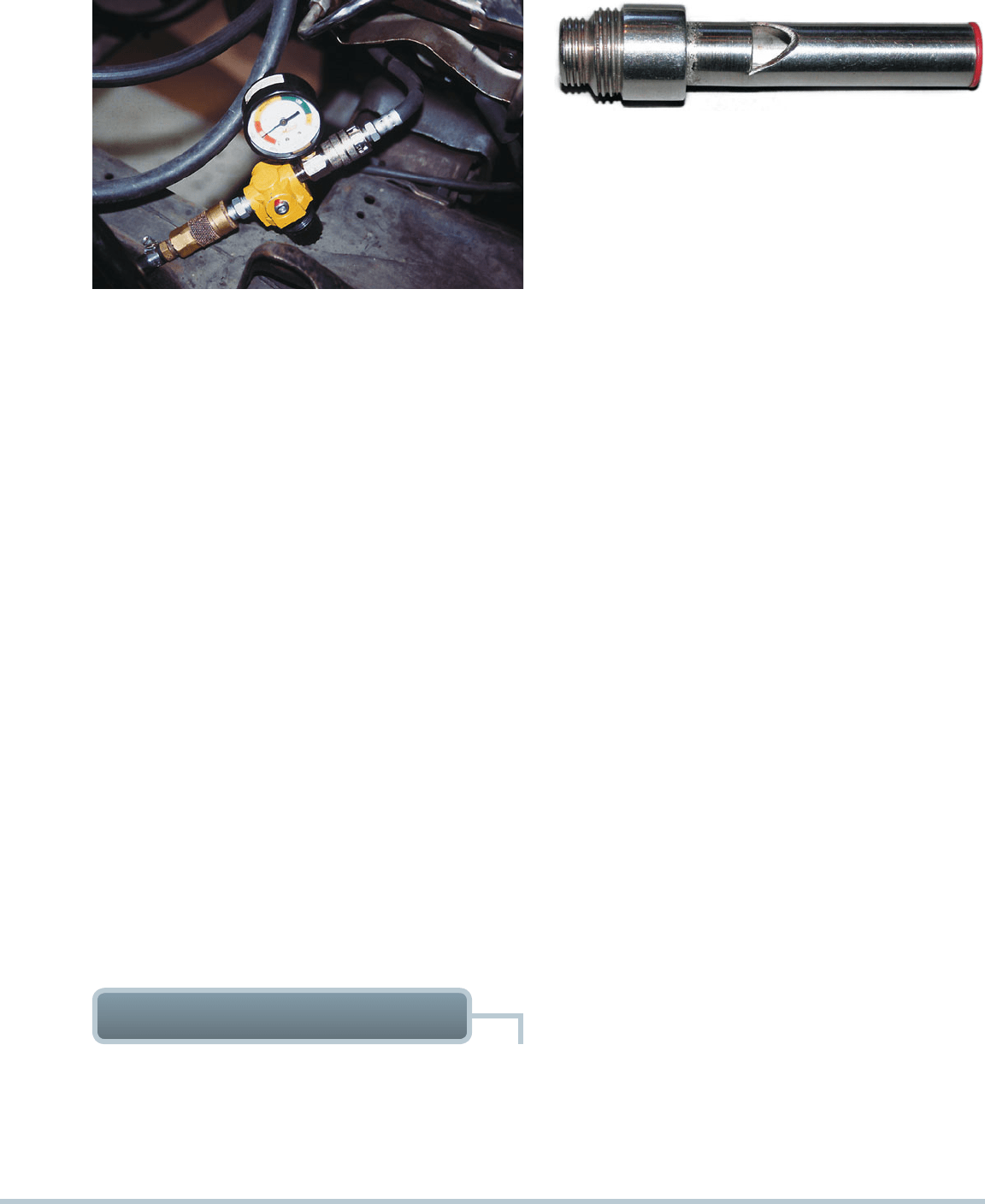
FIGURE 10–14 A whistle stop used to find top dead center.
Remove the spark plug and install the whistle stop, then rotate
the engine by hand. When the whistle stops making a sound,
the piston is at the top.
FIGURE 10–13 A typical handheld cylinder leakage tester.
One of the best tests that can be used to determine engine con-
dition is the cylinder leakage test. This test involves injecting
air under pressure into the cylinders one at a time. The amount
and location of any escaping air helps the technician determine
CYLINDER LEAKAGE TEST
the condition of the engine. The air is injected into the cylin-
der through a cylinder leakage gauge into the spark plug hole.
SEE FIGURE 10–13 . To perform the cylinder leakage test, take
the following steps:
STEP 1 For best results, the engine should be at normal
operating temperature (upper radiator hose hot and
pressurized).
STEP 2 The cylinder being tested must be at top dead
center (TDC) of the compression stroke.
SEE
FIGURE 10–14 .
NOTE: The greatest amount of wear occurs at
the top of the cylinder because of the heat gen-
erated near the top of the cylinders. The piston
ring flex also adds to the wear at the top of the
cylinder.
STEP 3 Calibrate the cylinder leakage unit as per manufac-
turer’s instructions.
STEP 4 Inject air into the cylinders one at a time, rotating the
engine as necessitated by firing order to test each
cylinder at TDC on the compression stroke.
STEP 5 Evaluate the results:
Less than 10% leakage: good
Less than 20% leakage: acceptable
Less than 30% leakage: poor
More than 30% leakage: definite problem
NOTE: If leakage seems unacceptably high, re-
peat the test, being certain that it is being per-
formed correctly and that the cylinder being
tested is at TDC on the compression stroke.
STEP 6 Check the source of air leakage.
a. If air is heard escaping from the oil filler cap, the
piston rings are worn or broken.
b. If air is observed bubbling out of the radiator, there
is a possible blown head gasket or cracked cylinder
head.
c. If air is heard coming from the throttle body or air
inlet on fuel injection-equipped engines, there is a
defective intake valve(s).
d. If air is heard coming from the tailpipe, there is a
defective exhaust valve(s).
144 CHAPTER 10
Cylinder Number RPM Drop When Ignition Is Shorted
1 75
2 70
3 15
4 65
5 75
6 70
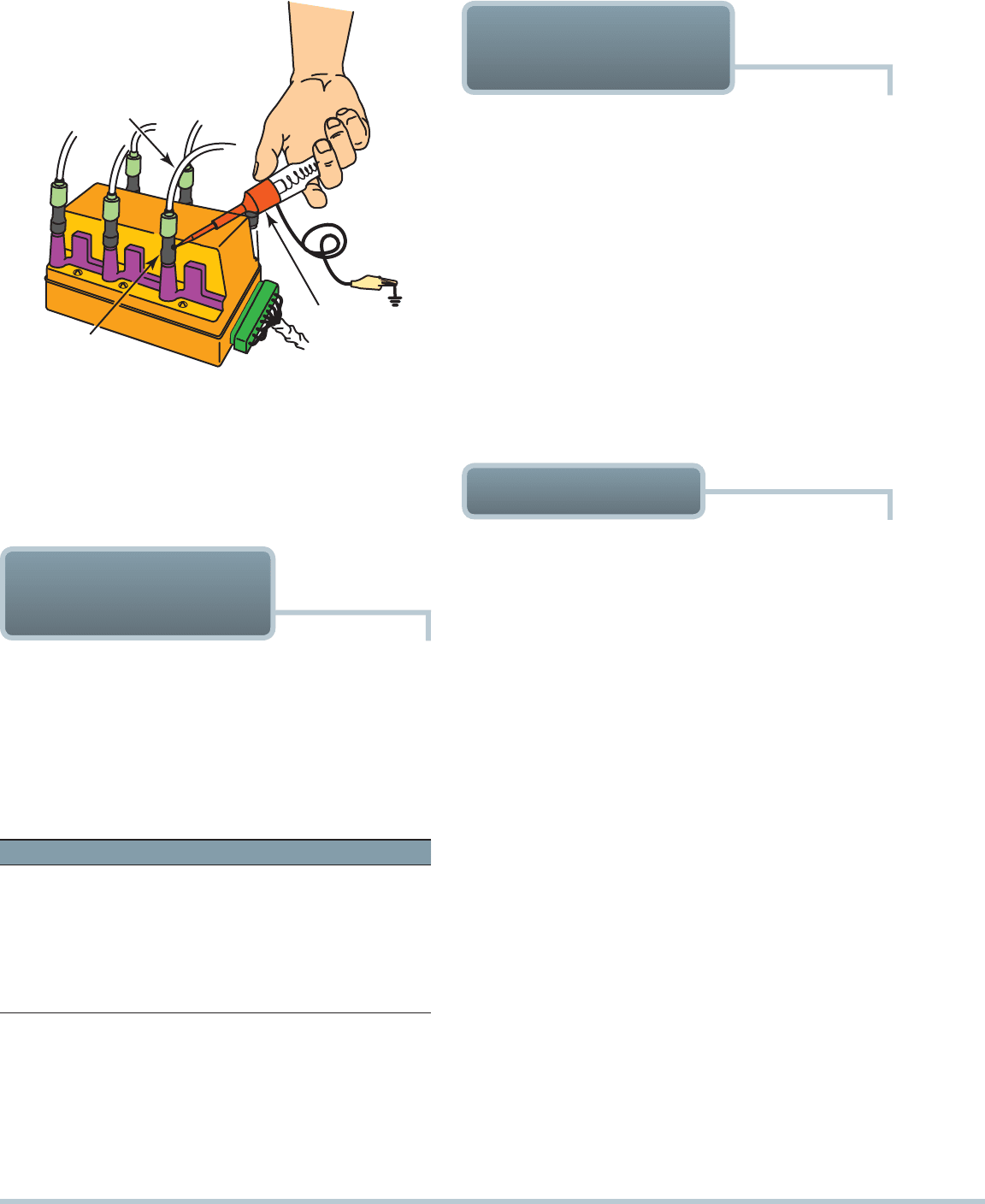
SPARK PLUG
WIRE
3" PIECE
OF HOSE
TEST
LIGHT
FIGURE 10–15 Using a vacuum hose and a test light to
ground one cylinder at a time on a distributorless ignition sys-
tem. This works on all types of ignition systems and provides
a method for grounding out one cylinder at a time without fear
of damaging any component. Do not short out a cylinder for
longer than 15 seconds to prevent possible damage to the
catalytic converter.
CYLINDER POWER
BALANCE TEST
Most large engine analyzers and scan tools have a cylinder
power balance feature. The purpose of a cylinder power bal-
ance test is to determine if all cylinders are contributing power
equally. It determines this by shorting out one cylinder at a
time. If the engine speed (RPM) does not drop as much for
one cylinder as for other cylinders of the same engine, then the
shorted cylinder must be weaker than the other cylinders. An
example follows:
Cylinder #3 is the weak cylinder.
NOTE: Most automotive test equipment uses automatic
means for testing cylinder balance. Be certain to cor-
rectly identify the offending cylinder. Cylinder #3 as
identified by the equipment may be the third cylinder in
the firing order instead of the actual cylinder #3.
POWER BALANCE
TEST PROCEDURE
When point-type ignition was used on all vehicles, the common
method for determining which, if any, cylinder was weak was to
remove a spark plug wire from one spark plug at a time while
watching a tachometer and a vacuum gauge. This method is
not recommended on any vehicle with any type of electronic
ignition. If any of the spark plug wires are removed from a spark
plug with the engine running, the ignition coil tries to supply
increasing levels of voltage attempting to jump the increasing
gap as the plug wires are removed. This high voltage could eas-
ily track the ignition coil, damage the ignition module, or both.
The acceptable method of canceling cylinders, which will
work on all types of ignition systems, including distributorless,
is to ground the secondary current for each cylinder.
SEE
FIGURE 10–15 . The cylinder with the least RPM drop is the
cylinder not producing its share of power.
Vacuum is pressure below atmospheric pressure and is mea-
sured in inches (or millimeters) of mercury (in. Hg). An engine in
good mechanical condition will run with high manifold vacuum.
Manifold vacuum is developed by the pistons as they move
down on the intake stroke to draw the charge from the throttle
body and intake manifold. Air to refill the manifold comes past
the throttle plate into the manifold. Vacuum will increase any-
time the engine turns faster or has better cylinder sealing while
the throttle plate remains in a fixed position. Manifold vacuum
will decrease when the engine turns more slowly or when the
cylinders no longer do an efficient job of pumping. Vacuum
tests include testing the engine for cranking vacuum, idle
vacuum, and vacuum at 2,500 RPM.
CRANKING VACUUM TEST Measuring the amount of
manifold vacuum during cranking is a quick and easy test
to determine if the piston rings and valves are properly seal-
ing. (For accurate results, the engine should be warm and the
throttle closed.) To perform the cranking vacuum test, take the
following steps:
STEP 1 Disable the ignition or fuel injection.
STEP 2 Connect the vacuum gauge to a manifold vacuum
source.
STEP 3 Crank the engine while observing the vacuum gauge.
Cranking vacuum should be higher than 2.5 in. Hg. (Normal
cranking vacuum is 3 to 6 in. Hg.) If it is lower than 2.5 in. Hg,
then the following could be the cause:
Too slow a cranking speed
Worn piston rings
VACUUM TESTS
ENGINE CONDITION DIAGNOSIS 145
Leaking valves
Excessive amounts of air bypassing the throttle plate
(This could give a false low vacuum reading. Common
sources include a throttle plate partially open or a high-
performance camshaft with excessive overlap.)
IDLE VACUUM TEST An engine in proper condition should
idle with a steady vacuum between 17 and 21 in. Hg.
SEE
FIGURE 10–16 .
NOTE: Engine vacuum readings vary with altitude. A
reduction of 1 in. Hg per 1,000 feet (300 m) of altitude
should be subtracted from the expected values if testing
a vehicle above 1,000 feet (300 m).
LOW AND STEADY VACUUM If the vacuum is lower
than normal yet the gauge reading is steady, the most common
causes include the following:
Retarded ignition timing
Retarded cam timing (check timing chain for exces-
siveslack or timing belt for proper installation)
SEE FIGURE 10–17 .
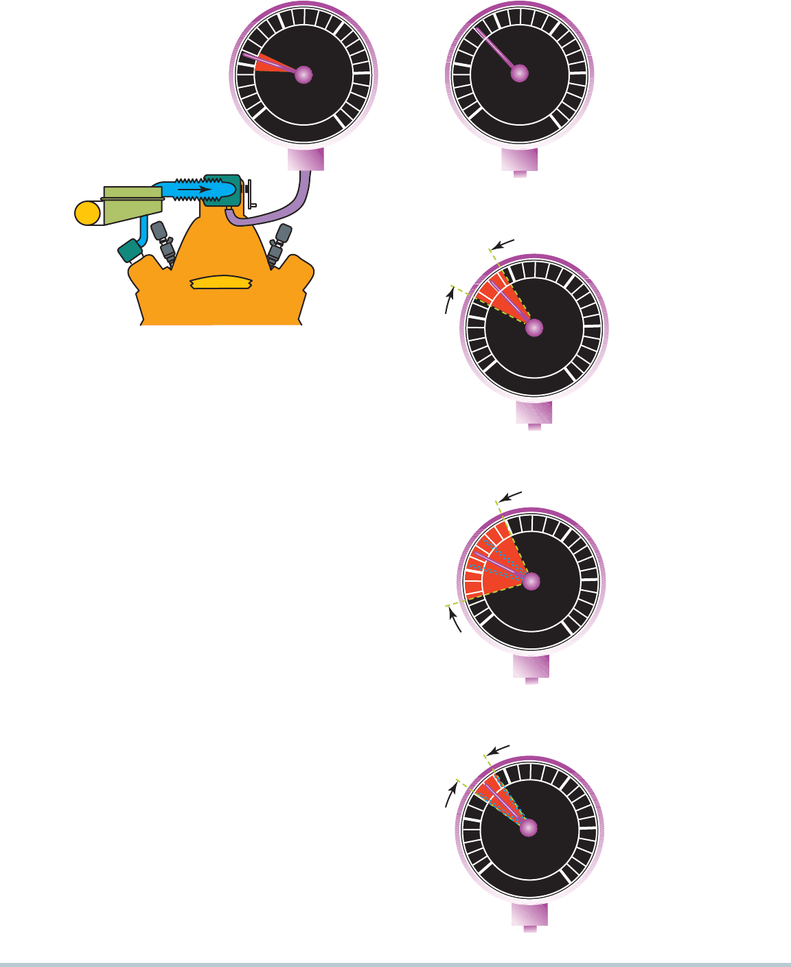
FLUCTUATING VACUUM If the needle drops, then returns
to a normal reading, then drops again, and again returns, this
indicates a sticking valve. A common cause of sticking valves is
lack of lubrication of the valve stems.
SEE FIGURES 10–18
THROUGH 10–26 . If the vacuum gauge fluctuates above and
below a center point, burned valves or weak valve springs may
be indicated. If the fluctuation is slow and steady, unequal fuel
mixture could be the cause.
Vacuum
in Hg
Pressure
P.S.I.
30
20
10
0
5
10
FIGURE 10–16 An engine in good mechanical condition
should produce 17 to 21 in. Hg of vacuum at idle at sea level.
Pressure
P.S.I.
30
20
10
0
5
10
Vacuum
in Hg
FIGURE 10–17 A steady but
low reading could indicate re-
tarded valve or ignition timing.
Pressure
P.S.I.
30
20
10
0
5
10
Vacuum
in Hg
FIGURE 10–18 A gauge
reading with the needle
fluctuating 3 to 9 in. Hg
below normal often indicates
a vacuum leak in the intake
system.
Pressure
P.S.I.
30
10
0
5
10
Vacuum
in Hg
20
FIGURE 10–19 A leaking
head gasket can cause the
needle to vibrate as it moves
through a range from below to
above normal.
Pressure
P.S.I.
30
20
10
0
5
10
Vacuum
in Hg
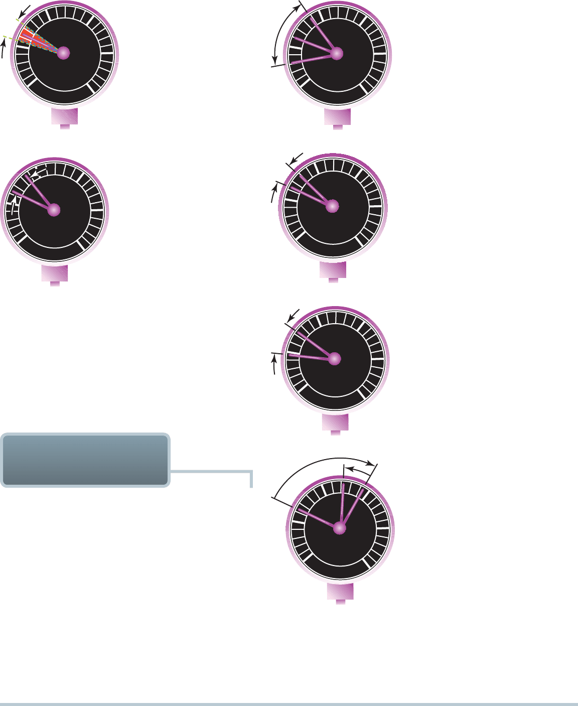
FIGURE 10–20 An oscillat-
ing needle 1 or 2 in. Hg below
normal could indicate an in-
correct air–fuel mixture (either
too rich or too lean).
146 CHAPTER 10
NOTE: A common trick that some technicians use is to
squirt some automatic transmission fluid (ATF) down
the throttle body or into the air inlet of a warm engine.
Often the idle quality improves, and normal vacuum
gauge readings are restored. The use of ATF does create
excessive exhaust smoke for a short time, but it should
not harm oxygen sensors or catalytic converters.
Pressure
P.S.I.
30
20
10
0
5
10
Vacuum
in Hg
FIGURE 10–22 If the needle
drops 1 or 2 in. Hg from the
normal reading, one of the
engine valves is burned or not
seating properly.
Pressure
P.S.I.
30
20
10
0
5
10
Vacuum
in Hg
FIGURE 10–23 Weak valve
springs will produce a normal
reading at idle, but as engine
speed increases, the needle
will fluctuate rapidly between
12 and 24 in. Hg.
Pressure
P.S.I.
30
20
10
0
5
10
Vacuum
in Hg
FIGURE 10–24 A steady
needle reading that drops
2or 3 in. Hg when the engine
speed is increased slightly
above idle indicates that the
ignition timing is retarded.
Pressure
P.S.I.
30
20
10
0
5
10
Vacuum
in Hg
FIGURE 10–25 A steady
needle reading that rises
2or 3 in. Hg when the engine
speed is increased slightly
above idle indicates that the
ignition timing is advanced.
Pressure
P.S.I.
30
20
10
0
5
10
Vacuum
in Hg
FIGURE 10–26 A needle
that drops to near zero
when the engine is acceler-
ated rapidly and then rises
slightly to a reading below
normal indicates an exhaust
restriction.
Pressure
P.S.I.
30
20
10
0
5
10
Vacuum
in Hg
FIGURE 10–21 A rapidly
vibrating needle at idle that
becomes steady as engine
speed is increased indicates
worn valve guides.
EXHAUST
RESTRICTION TEST
If the exhaust system is restricted, the engine will be low on
power yet smooth. Common causes of restricted exhaust
include the following:
Clogged catalytic converter. Always check the ignition
and fuel-injection systems for faults that could cause
excessive amounts of unburned fuel to be exhausted.
Excessive unburned fuel can overheat the catalytic con-
verter and cause the beads or structure of the converter
to fuse together, creating the restriction. A defective fuel
delivery system could also cause excessive unburned
fuel to be dumped into the converter.
Clogged or restricted muffler. This can cause low
power. Often a defective catalytic converter will shed par-
ticles that can clog a muffler. Broken internal baffles can
also restrict exhaust flow.
Damaged or defective piping. This can reduce the
power of any engine. Some exhaust pipe is constructed
with double walls, and the inside pipe can collapse and
form a restriction that is not visible on the outside of the
exhaust pipe.
ENGINE CONDITION DIAGNOSIS 147
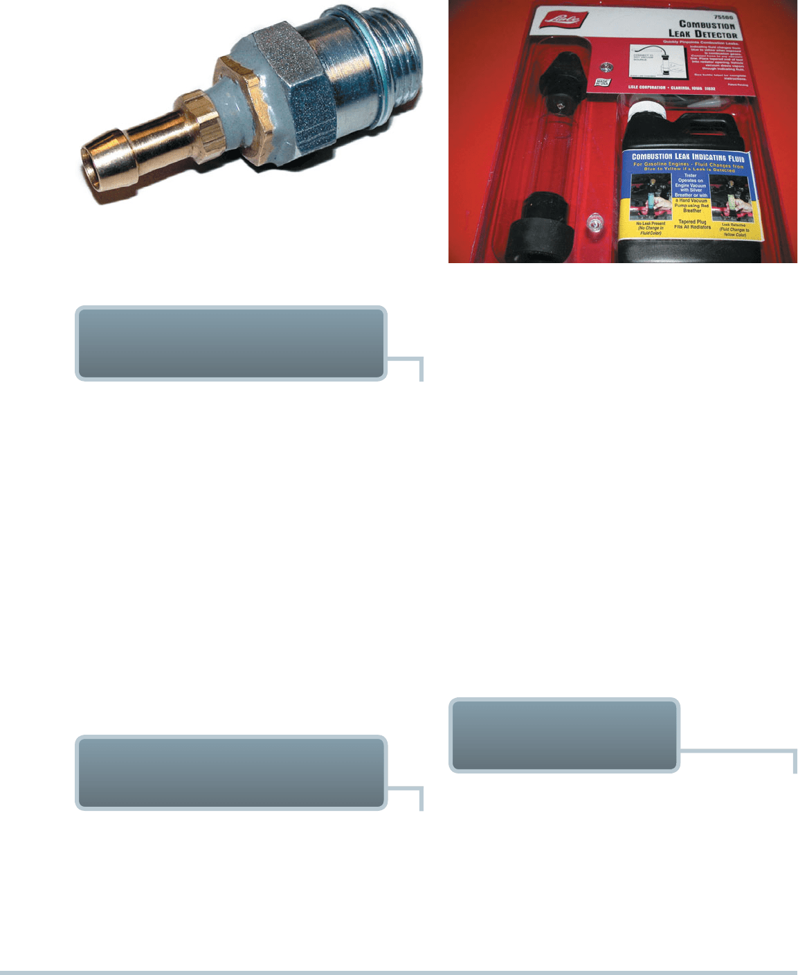
FIGURE 10–27 A technician-made adapter used to test ex-
haust system back pressure.
FIGURE 10–28 A tester that uses a blue liquid to check for
exhaust gases in the exhaust, which would indicate a head
gasket leak problem.
TESTING BACK PRESSURE
WITH A VACUUM GAUGE
A vacuum gauge can be used to measure manifold vacuum
at a high idle (2,000 to 2,500 RPM). If the exhaust system is
restricted, pressure increases in the exhaust system. This pres-
sure is called back pressure. Manifold vacuum will drop gradu-
ally if the engine is kept at a constant speed if the exhaust is
restricted.
The reason the vacuum will drop is that all exhaust leav-
ing the engine at the higher engine speed cannot get through
the restriction. After a short time (within 1 minute), the exhaust
tends to “pile up” above the restriction and eventually remains
in the cylinder of the engine at the end of the exhaust stroke.
Therefore, at the beginning of the intake stroke, when the piston
traveling downward should be lowering the pressure (raising the
vacuum) in the intake manifold, the extra exhaust in the cylinder
lowers the normal vacuum. If the exhaust restriction is severe
enough, the vehicle can become undriveable because cylinder
filling cannot occur except at idle.
TESTING BACK PRESSURE
WITH A PRESSURE GAUGE
Exhaust system back pressure can be measured directly by in-
stalling a pressure gauge into an exhaust opening. This can be
accomplished in one of the following ways:
With an oxygen sensor. Use a back pressure gauge and
adapter or remove the inside of an old, discarded oxygen
sensor and thread in an adapter to convert to a vacuum
or pressure gauge.
DIAGNOSING HEAD
GASKET FAILURE
Several items can be used to help diagnose a head gasket failure:
Exhaust gas analyzer. With the radiator cap removed,
place the probe from the exhaust analyzer above the ra-
diator filler neck. If the HC reading increases, the exhaust
(unburned hydrocarbons) is getting into the coolant from
the combustion chamber.
Chemical test. A chemical tester using blue liquid is also
available. The liquid turns yellow if combustion gases are
present in the coolant.
SEE FIGURE 10–28 .
With the exhaust gas recirculation (EGR) valve. Re-
move the EGR valve and fabricate a plate to connect to a
pressure gauge.
With the air-injection reaction (AIR) check valve. Re-
move the check valve from the exhaust tubes leading
down to the exhaust manifold. Use a rubber cone with a
tube inside to seal against the exhaust tube. Connect the
tube to a pressure gauge.
NOTE: An adapter can be easily made by inserting
a metal tube or pipe. A short section of brake line
works great. The pipe can be brazed to the oxygen
sensor housing or it can be glued in with epoxy. An
18-millimeter compression gauge adapter can also
be adapted to fit into the oxygen sensor opening.
SEE FIGURE 10–27 .
At idle, the maximum back pressure should be less than
1.5 PSI (10 kPa), and it should be less than 2.5 PSI (15 kPa) at
2,500 RPM.

148 CHAPTER 10
NOTE: Some automobile manufacturers combine the
dash warning lights for oil pressure and coolant temper-
ature into one light, usually labeled “engine.” Therefore,
when the engine light comes on, the technician should
check for possible coolant temperature and/or oil pres-
sure problems.
COOLANT TEMPERATURE LIGHT Most vehicles are
equipped with a coolant temperature gauge or dash warning
light. The warning light may be labeled “coolant,” “hot,” or
“temperature.” If the coolant temperature warning light comes
on during driving, this usually indicates that the coolant tem-
perature is above a safe level, or above about 250°F (120°C).
Normal coolant temperature should be about 200° to 220°F
(90° to 105°C).
If the coolant temperature light comes on during driving,
the following steps should be followed to prevent possible en-
gine damage:
1. Turn off the air conditioning and turn on the heater. The
heater will help get rid of some of the heat in the cooling
system.
2. Raise the engine speed in neutral or park to increase the
circulation of coolant through the radiator.
3. If possible, turn the engine off and allow it to cool (this may
take over an hour).
4. Do not continue driving with the coolant temperature light
on (or the gauge reading in the red warning section or
above 260°F), or serious engine damage may result.
NOTE: If the engine does not feel or smell hot, it is pos-
sible that the problem is a faulty coolant temperature
sensor or gauge.
Bubbles in the coolant. Remove the coolant pump belt
to prevent pump operation. Remove the radiator cap and
start the engine. If bubbles appear in the coolant before it
begins to boil, a defective head gasket or cracked cylin-
der head is indicated.
Excessive exhaust steam. If excessive water or steam
is observed coming from the tailpipe, this means that
coolant is getting into the combustion chamber from a
defective head gasket or a cracked head. If there is leak-
age between cylinders, the engine usually misfires and
a power balancer test and/or compression test can be
used to confirm the problem.
If any of the preceding indicators of head gasket failure oc-
cur, remove the cylinder head(s) and check all of the following:
1. Head gasket
2. Sealing surfaces—for warpage
3. Castings—for cracks
NOTE: A leaking thermal vacuum valve can cause symp-
toms similar to those of a defective head gasket. Most
thermal vacuum valves thread into a coolant passage,
and they often leak only after they get hot.
Misfire Diagnosis
If a misfire goes away with propane added to the air
inlet, suspect a lean injector.
TECH TIP
Most vehicles are equipped with several dash warning lights of-
ten called “telltale” or “idiot” lights. These lights are often the only
warning a driver receives that there may be engine problems. A
summary of typical dash warning lights and their meanings follows.
OIL (ENGINE) LIGHT The red oil light indicates that the
engine oil pressure is too low (usually lights when oil pressure
is 4 to 7 PSI [20 to 50 kPa]). Normal oil pressure should be 10 to
60 PSI (70 to 400 kPa) or 10 PSI per 1,000 engine RPM.
When this light comes on, the driver should shut off the en-
gine immediately and check the oil level and condition for possible
dilution with gasoline caused by a fuel system fault. If the oil level
is okay, then there is a possible serious engine problem or a pos-
sible defective oil pressure sending (sender) unit. The automotive
technician should always check the oil pressure using a reliable
mechanical oil pressure gauge if low oil pressure is suspected.
DASH WARNING LIGHTS
ENGINE CONDITION DIAGNOSIS 149
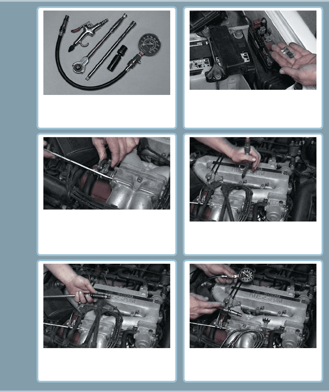
The tools and equipment needed to perform a compres-
sion test include a compression gauge, an air nozzle,
and the socket ratchets and extensions that may be
necessary to remove the spark plugs from the engine.
1
To prevent ignition and fuel-injection operation while
the engine is being cranked, remove both the fuel-
injection fuse and the ignition fuse. If the fuses cannot
be removed, disconnect the wiring connectors for the
injectors and the ignition system.
2
Before removing the spark plugs, use an air nozzle to
blow away any dirt that may be around the spark plug.
This step helps prevent debris from getting into the
engine when the spark plugs are removed.
4
3
Remove all of the spark plugs. Be sure to mark the
spark plug wires so that they can be reinstalled onto the
correct spark plugs after the compression test has been
performed.
5
Select the proper adapter for the compression gauge.
The threads on the adapter should match those on the
spark plug.
6
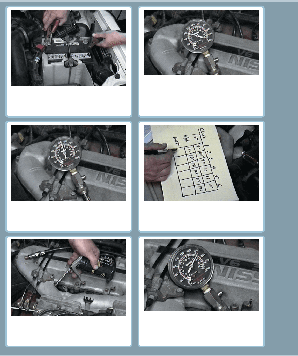
COMPRESSION TEST
CONTINUED
Block open the throttle (and choke if the engine is
equipped with a carburetor). Here a screwdriver is being
used to wedge the throttle linkage open. Keeping the
throttle open ensures that enough air will be drawn into
the engine so that the compression test results will be
accurate.
150 CHAPTER 10
COMPRESSION TEST (CONTINUED)
If necessary, connect a battery charger to the battery
before starting the compression test. It is important that
consistent cranking speed be available for each cylinder
being tested.
7
8
After the engine has been cranked for four “puffs,”
stop cranking the engine and observe the compression
gauge.
9
Record the first puff and this final reading for each
cylinder. The final readings should all be within
20% of each other.
10
If a cylinder(s) is lower than most of the others, use
an oil can and squirt two squirts of engine oil into
the cylinder and repeat the compression test. This is
called performing a wet compression test.
11
If the gauge reading is now much higher than the
first test results, then the cause of the low com-
pression is due to worn or defective piston rings.
The oil in the cylinder temporarily seals the rings
which causes the higher reading.
12
Make a note of the reading on the gauge after the first
“puff,” which indicates the first compression stroke
that occurred on that cylinder as the engine was being
rotated. If the first puff reading is low and the reading
gradually increases with each puff, weak or worn piston
rings may be indicated.