Halderman J.D., Linder J. Automotive Fuel and Emissions Control Systems
Подождите немного. Документ загружается.

ENGINE CONDITION DIAGNOSIS 151
5. A cylinder leakage test fills the cylinder with compressed
air, and the gauge indicates the percentage of leakage.
6. A cylinder balance test indicates whether all cylinders are
working equally.
7. Testing engine vacuum is another procedure that can help
the service technician determine engine condition.
1. The first step in diagnosing engine condition is to perform
a thorough visual inspection, including a check of oil and
coolant levels and condition.
2. Oil leaks can be found by using a white powder or a fluo-
rescent dye and a black light.
3. Many engine-related problems make a characteristic noise.
4. A compression test can be used to test the condition of
valves and piston rings.
SUMMARY
5. Describe the cylinder leakage test.
6. Describe how a vacuum gauge would indicate if the valves
were sticking in their guides.
7. Describe the test procedure for determining if the exhaust
system is restricted (clogged) using a vacuum gauge.
1. Describe the visual checks that should be performed on an
engine if a mechanical malfunction is suspected.
2. List three simple items that could cause excessive oil
consumption.
3. List three simple items that could cause engine noises.
4. Describe how to perform a compression test and how to
determine what is wrong with an engine based on a com-
pression test result.
REVIEW QUESTIONS
4. A good engine should produce how much compression
during a running (dynamic) compression test at idle?
a. 150–200 PSI
b. 100–150 PSI
c. 60–90 PSI
d. 30–60 PSI
5. A smoothly operating engine depends on ________ .
a. High compression on most cylinders
b. Equal compression between cylinders
c. Cylinder compression levels above 100 PSI (700 kPa)
and within 70 PSI (500 kPa) of each other
d. Compression levels below 100 PSI (700 kPa) on most
cylinders
6. A good reading for a cylinder leakage test would
be ________ .
a. Within 20% between cylinders
b. All cylinders below 20% leakage
c. All cylinders above 20% leakage
d. All cylinders above 70% leakage and within 7% of
each other
1. Technician A says that the paper test could detect a
burned valve. Technician B says that a grayish white stain
on the engine could be a coolant leak. Which technician is
correct?
a. Technician A only
b. Technician B only
c. Both Technicians A and B
d. Neither Technician A nor B
2. Two technicians are discussing oil leaks. Technician A
says that an oil leak can be found using a fluorescent dye
in the oil with a black light to check for leaks. Technician B
says that a white spray powder can be used to locate oil
leaks. Which technician is correct?
a. Technician A only
b.
Technician B only
c. Both Technicians A and B
d. Neither Technician A nor B
3. Which of the following is the least likely to cause an engine
noise?
a. Carbon on the pistons
b. Cracked exhaust manifold
c. Loose accessory drive belt
d. Vacuum leak
CHAPTER QUIZ

152 CHAPTER 10
9. Technician A says that a leaking head gasket can be tested
for using a chemical tester. Technician B says that leaking
head gasket can be found using an exhaust gas analyzer.
a. Technician A only
b. Technician B only
c. Both Technicians A and B
d. Neither Technician A nor B
10. The low oil pressure warning light usually comes
on ________ .
a. Whenever an oil change is required
b. Whenever oil pressure drops dangerously low
(4 to 7PSI)
c. Whenever the oil filter bypass valve opens
d. Whenever the oil filter antidrainback valve opens
7. Technician A says that during a power balance test, the
cylinder that causes the biggest RPM drop is the weak
cylinder. Technician B says that if one spark plug wire is
grounded out and the engine speed does not drop, a weak
or dead cylinder is indicated. Which technician is correct?
a. Technician A only
b. Technician B only
c. Both Technicians A and B
d. Neither Technician A nor B
8. Cranking vacuum should be ________ .
a. 2.5 in. Hg or higher
b. Over 25 in. Hg
c. 17 to 21 in. Hg
d. 6 to 16 in. Hg
ON-BOARD DIAGNOSIS 153
chapter
ON-BOARD DIAGNOSIS
11
OBJECTIVES: After studying Chapter 11 , the reader should be able to: • Prepare for ASE Engine Performance (A8)
certification test content area “D” (Emissions Control Systems Diagnosis and Repair (Including OBD-II)). • Explain the purpose and
function of onboard diagnosis. • List the various duties of the diagnostic executive (task master). • List five continuous monitors.
• List five noncontinuous monitors.
KEY TERMS: California Air Resources Board (CARB) 153 • Component identification (CID) 160 • Comprehensive component
monitor (CCM) 154 • Diagnostic executive 154 • Enable criteria 156 • Exponentially weighted moving average (EWMA)
monitor 156 • Federal Test Procedure (FTP) 154 • Freeze-frame 154 • Functionality 155 • Malfunction indicator
lamp (MIL) 153 • On-board diagnosis (OBD) 153 • Parameter identification (PID) 160 • Rationality 155 • Society
of Automotive Engineers (SAE) 157 • Test identification (TID) 160 • Task manager 154
PURPOSE AND FUNCTION OF OBD II During the
1980s, most manufacturers began equipping their vehicles with
full-function control systems capable of alerting the driver of a
malfunction and of allowing the technician to retrieve codes
that identify circuit faults. These early diagnostic systems were
meant to reduce emissions and speed up vehicle repair.
The automotive industry calls these systems On-board
Diagnostics (OBDs). The California Air Resources Board
(CARB) developed the first regulation requiring manufacturers
selling vehicles in that state to install OBD. OBD Generation I
(OBD I) applies to all vehicles sold in California beginning with
the 1988 model year. It specifies the following requirements:
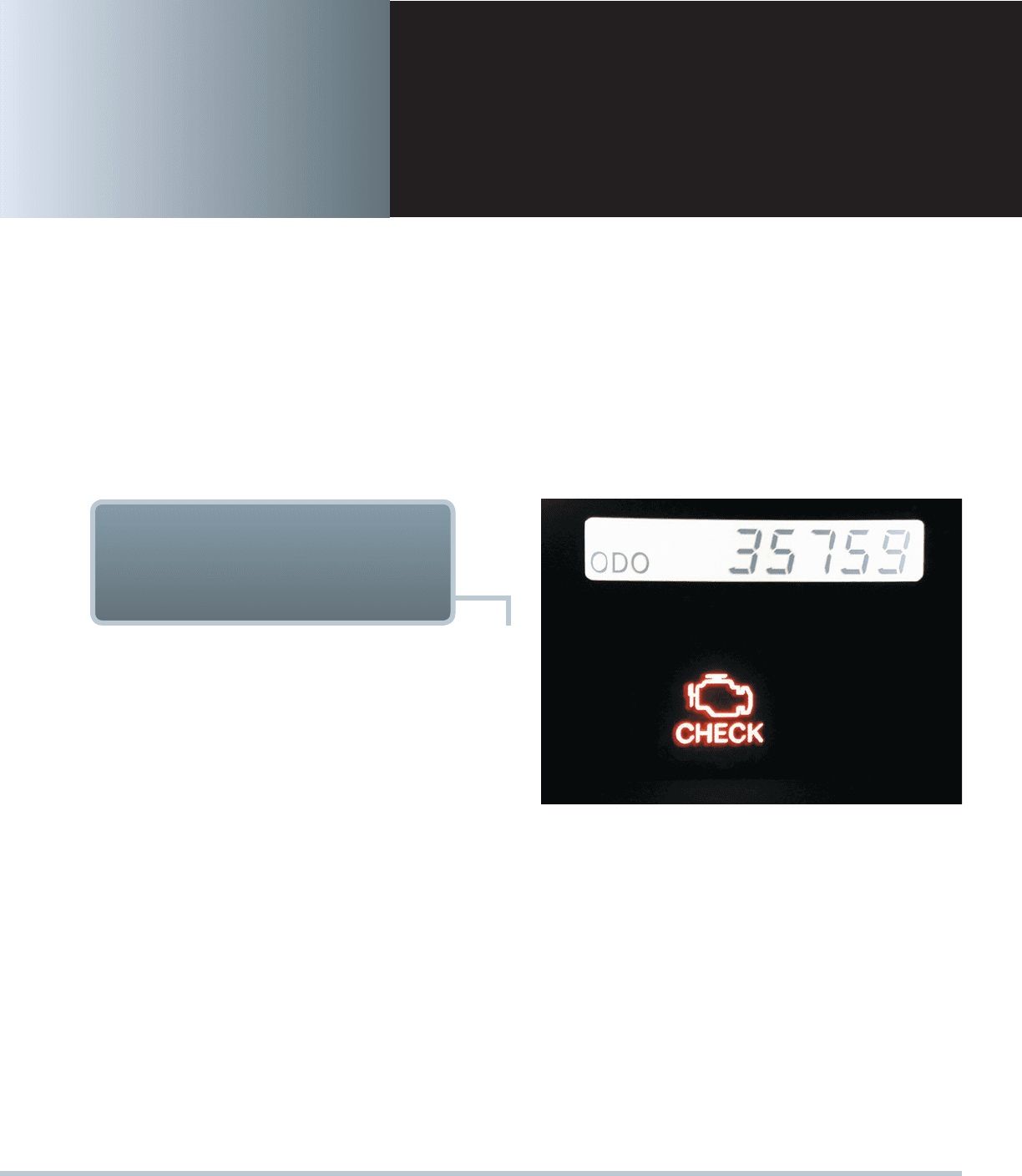
1. An instrument panel warning lamp able to alert the driver of
certain control system failures, now called a malfunction
indicator lamp (MIL).
SEE FIGURE 11–1.
2. The system’s ability to record and transmit diagnostic
trouble codes (DTCs) for emission-related failures.
3. Electronic system monitoring of the HO 2 S, EGR valve,
and evaporative purge solenoid. Although not U.S. EPA
required, during this time most manufacturers also
equipped vehicles sold outside of California with OBD I.
By failing to monitor the catalytic converter, the evapora-
tive system for leaks, and the presence of engine misfire, OBDI
ON-BOARD DIAGNOSTICS
GENERATION-II (OBD-II)
SYSTEMS
FIGURE 11–1 A typical malfunction indicator lamp (MIL)
often labeled “check engine” or “service engine soon” (SES).
did not do enough to lower automotive emissions. This led the
CARB and the EPA to develop OBD Generation II (OBD II).
OBD-II OBJECTIVES Generally, the CARB defines an
OBD-II-equipped vehicle by its ability to do the following:
1. Detect component degradation or a faulty emission- related
system that prevents compliance with federal emission
standards.
2. Alert the driver of needed emission-related repair or
maintenance.
3. Use standardized DTCs and accept a generic scan tool.

154 CHAPTER 11
be stored and the MIL illuminated during the second trip. The
two types of monitors are continuous and noncontinuous.
CONTINUOUS MONITORS As required conditions are
met, continuous monitors begin to run. These continuous moni-
tors will run for the remainder of the vehicle drive cycle. The
three continuous monitors are as follows:
Comprehensive component monitor (CCM). This
monitor watches the sensors and actuators in the
OBD-II system. Sensor values are constantly compared
with known-good values stored in the PCM’s memory.
The CCM is an internal program in the PCM designed
to monitor a failure in any electronic component or circuit
(including emission-related and non–emission-related cir-
cuits) that provide input or output signals to the PCM. The
PCM considers that an input or output signal is inoperative
when a failure exists because of an open circuit or out-of-
range value or if an onboard rationality check fails. If an
emission-related fault is detected, the PCM will set a code
and activate the MIL (requires two consecutive trips).
Many PCM sensors and output devices are tested
at key-on or immediately after engine start-up. However,
some devices are tested by the CCM only after the en-
gine meets certain engine conditions. The number of
times the CCM must detect a fault before it will activate
the MIL depends upon the manufacturer, but most re-
quire two consecutive trips to activate the MIL. The com-
ponents tested by the CCM include the following:
Four-wheel-drive low switch
Brake switch
Camshaft (CMP) and crankshaft (CKP) sensors
Clutch switch (manual transmissions/transaxles only)
Cruise servo switch
Engine coolant temperature (ECT) sensor
EVAP purge sensor or switch
Fuel composition sensor
Intake air temperature (IAT) sensor
Knock sensor (KS)
Manifold absolute pressure (MAP) sensor
Mass airflow (MAF) sensor
Throttle-position (TP) sensor
Transmission temperature sensor
Transmission turbine speed sensor
Vacuum sensor
Vehicle speed (VS) sensor
EVAP canister purge and EVAP purge vent solenoid
Idle air control (IAC)
Ignition control system
Transmission torque converter clutch solenoid
Transmission shift solenoids
Misfire monitor. This monitor looks at engine mis-
fire. The PCM uses the information received from the
crankshaft position sensor (CKP) to calculate the time
These requirements apply to all 1996 and later model
light-duty vehicles. The Clean Air Act of 1990 directed the
EPA to develop new regulations for OBD. The primary pur-
pose of OBDII is emission related, whereas the primary pur-
pose of OBDI (1988) was to detect faults in sensors or sensor
circuits. OBD-II regulations require that not only sensors be
tested but also all exhaust emission control devices and that
they be verified for proper operation.
All new vehicles must pass the Federal Test Procedure
(FTP) for exhaust emissions while being tested for 1874 seconds
on dynamometer rollers that simulate the urban drive cycle around
downtown Los Angeles.
NOTE: IM 240 is simply a shorter 240-second version of
the 1874-second federal test procedure.
The regulations for OBD-II vehicles state that the vehicle
computer must be capable of testing for, and determining, if
the exhaust emissions are within 1.5 times the FTP limits. To
achieve this goal, the computer must do the following:
1. Test all exhaust emission system components for correct
operation.
2. Actively operate the system and measure the results.
3. Continuously monitor all aspects of the engine operation
to be certain that the exhaust emissions do not exceed
1.5times the FTP limit.
4. Check engine operation for misfire.
5. Turn on the MIL (check engine) if the computer senses a
fault in a circuit or system.
6. Record a freeze-frame, which is a snapshot of all key
engine data at the time the DTC was set.
7. Flash the MIL if an engine misfire occurs that could dam-
age the catalytic converter.
On OBD-II systems, the powertrain control module (PCM) in-
corporates a special segment of software. On Ford and GM
systems, this software is called the diagnostic executive. On
Chrysler systems, it is called the task manager. This software
program is designed to manage the operation of all OBD-II
monitors by controlling the sequence of steps necessary to ex-
ecute the diagnostic tests and monitors.
DIAGNOSTIC EXECUTIVE
AND TASK MANAGER
MONITORS
A monitor is an organized method of testing a specific part of
the system. Monitors are simply tests that the computer per-
forms to evaluate components and systems. If a component or
system failure is detected while a monitor is running, a DTC will

ON-BOARD DIAGNOSIS 155
However, OBD-II also requires that inputs from powertrain
components to the PCM be tested for rationality and that out-
puts to powertrain components from the PCM be tested for
functionality. Both inputs and outputs are to be checked elec-
trically. Rationality checks refer to a PCM comparison of input
value to values from other sensors to determine if they make
sense and are normal (rational):
Example:
TPS 3 V
MAP 18 in. Hg
RPM 700 RPM
PRNDL Park
NOTE: Comprehensive component monitors are contin-
uous. Therefore, enabling conditions do not apply.
Monitor runs continuously.
Monitor includes sensors, switches, relays, solenoids,
and PCM hardware.
All are checked for opens, shorts-to-ground, and
shorts-to-voltage.
Inputs are checked for rationality.
Outputs are checked for functionality.
Most are one-trip DTCs.
Freeze-frame is priority 3.
Three consecutive good trips are used to extinguish
the MIL.
Forty warm-up cycles are required to self-erase DTC
and freeze-frame.
Two minutes run time without reoccurrence of the fault
constitutes a “good trip.”
CONTINUOUS RUNNING MONITORS Continuous mon-
itors run continuously and only stop if they fail and include:
Fuel system: rich/lean.
Misfire: catalyst damaging/FTP (emissions).
Two-trip faults (except early generation catalyst damag-
ing misfire).
MIL, DTC, freeze-frame after two consecutive faults.
Freeze-frame is priority 2 on first trip.
Freeze-frame is priority 4 on maturing trip.
Three consecutive good trips in a similar condition
window are used to extinguish the MIL.
Forty warm-up cycles are used to erase DTC and freeze-
frame (80 to erase one-trip failure if similar conditions
cannot be met).
ONCE PER TRIP MONITORS
Monitor runs once per trip, pass or fail.
O
2
response, O
2
heaters, EGR, purge flow EVAP leak,
secondary air, catalyst.
Two-trip DTCs.
between the edges of the reluctor as well as the rota-
tional speed and acceleration. By comparing the accel-
eration of each firing event, the PCM can determine if a
cylinder is not firing correctly.
Misfire type A. Upon detection of a misfire type A
(200revolutions), which would cause catalyst damage,
the MIL will blink once per second during the actual
misfire, and a DTC will be stored.
Misfire type B. Upon detection of a misfire type B
(1,000revolutions), which will exceed 1.5 times the EPA
federal test procedure (FTP) standard or cause a vehicle
to fail an inspection and maintenance tailpipe emissions
test, the MIL will illuminate, and a DTC will be stored.
The DTC associated with multiple cylinder misfire for a
type A or type B misfire is DTC P0300. The DTCs associated
with an individual cylinder misfire for a type A or type B misfire
are DTCs P0301, P0302, P0303, P0304, P0305, P0306, P0307,
P0308, P0309, and P0310.
Fuel trim monitor. The PCM continuously monitors short-
and long-term fuel trim. Constantly updated adaptive fuel
tables are stored in long-term memory (KAM) and used by
the PCM for compensation due to wear and aging of the
fuel system components. The MIL will illuminate when the
PCM determines the fuel trim values have reached and
stayed at their limits for too long a period of time.
NONCONTINUOUS MONITORS Noncontinuous moni-
tors run (at most) once per vehicle drive cycle. The noncontinu-
ous monitors are as follows:
O 2 S monitor
O 2 S heater monitor
Catalyst monitor
EGR monitor
EVAP monitor
Secondary AIR monitor
Transmission monitor
PCV system monitor
Thermostat monitor
Once a noncontinuous monitor has run to completion, it
will not be run again until the conditions are met during the next
vehicle drive cycle. Also, after a noncontinuous monitor has run
to completion, the readiness status on your scan tool will show
“complete” or “done” for that monitor. Monitors that have not
run to completion will show up on your scanner as “incomplete.”
COMPREHENSIVE COMPONENT MONITOR The cir-
cuits and components covered by the comprehensive compo-
nent monitor (CCM) do not include those directly monitored by
another monitor.
OBD-II MONITOR
INFORMATION
156 CHAPTER 11
MIL, DTC, freeze-frame after two consecutive faults.
Freeze-frame is priority 1 on first trip.
Freeze-frame is priority 3 on maturing trip.
Three consecutive good trips are used to extinguish
the MIL.
Forty warm-up cycles are used to erase DTC
and freeze-frame.
EXPONENTIALLY WEIGHTED MOVING AVERAGE (EWMA)
MONITORS The exponentially weighted moving average
(EWMA) monitor is a mathematical method used to determine
performance. This method smooths out any variables in the read-
ings over time and results in a running average. This method is
used by some vehicle manufacturers for two monitors.
1. Catalyst monitor.
2. EGR monitor.
ENABLING CRITERIA
With so many different tests (monitors) to run, the PCM needs an
internal director to keep track of when each monitor should run.
As mentioned, different manufacturers have different names for
this director, such as the diagnostic executive or the task man-
ager. Each monitor has enabling criteria. These criteria are a set
of conditions that must be met before the task manager will give
the go-ahead for each monitor to run. Most enabling criteria fol-
low simple logic, such as follows:
The task manager will not authorize the start of the O
2
S
monitor until the engine has reached operating tempera-
ture and the system has entered closed loop.
The task manager will not authorize the start of the EGR
monitor when the engine is at idle because the EGR is
always closed at this time.
Because each monitor is responsible for testing a differ-
ent part of the system, the enabling criteria can differ greatly
from one monitor to the next. The task manager must decide
when each monitor should run, and in what order, to avoid
confusion.
There may be a conflict if two monitors were to run at the
same time. The results of one monitor might also be tainted if
a second monitor were to run simultaneously. In such cases,
the task manager decides which monitor has a higher priority.
Some monitors also depend on the results of other monitors
before they can run.
A monitor may be classified as pending if a failed sensor
or other system fault is keeping it from running on schedule.
The task manager may suspend a monitor if the conditions
are not correct to continue. For example, if the catalyst monitor
is running during a road test and the PCM detects a misfire,
the catalyst monitor will be suspended for the duration of the
misfire.
What is a Drive Cycle?
A drive cycle is a vehicle being driven under speci-
fied speed and times that will allow all monitors to
run. In other words, the powertrain control module
(PCM) is looking at a series of data points represent-
ing speed and time and determines from these data
points when the conditions are right to perform a
monitor or a test of a component. These data points,
and therefore the drive cycle, are vehicle specific and
are not the same for each vehicle. Some common
conditions for a drive cycle to successfully run all of
the monitors include:
1. Cold start intake air temperature (IAT) and engine
coolant temperature (ECT) close to each other
indicating that the engine has cooled to the tem-
perature of the surrounding air temperature.
2. Fuel level within a certain range usually between
15% and 85%.
3. Vehicle speed within a certain speed range for an
certain amount of time usually 4 to 12 minutes.
4. Stop and idle for a certain time.
Each monitor requires its own set of parameters
needed to run the test and sometimes these condi-
tions cannot be met. For example, some evaporate
emissions control (EVAP) systems require a tem-
perature that may not be possible in winter months in
a cold climatic area.
A typical universal drive cycle that works for
many vehicles includes the following steps.
MIL must be off.
No DTCs present.
Fuel fill between 15% and 85%.
Cold start—Preferred 8-hour soak at 68°F to 86°F.
Alternative ECT below 86°F.
STEP 1 With the ignition off, connect scan tool.
STEP 2 Start engine and drive between 20 and
30mph for 22 minutes, allowing speed
to vary.
STEP 3 Stop and idle for 40 seconds, gradually
accelerate to 55mph.
STEP 4 Maintain 55 mph for 4 minutes using a
steady throttle input.
STEP 5 Stop and idle for 30 seconds, then acceler-
ate to 30 mph.
STEP 6 Maintain 30 mph for 12 minutes.
STEP 7 Repeat steps 4 and 5 four times.
Using scan tool, check readiness. Always check
service information for the exact drive cycle condi-
tions for the vehicle being serviced for best results.
?
FREQUENTLY ASKED QUESTION
ON-BOARD DIAGNOSIS 157
TRIP A trip is defined as a key-on condition that contains
the necessary conditions for a particular test to be performed
followed by a key-off. These conditions are called the enable
criteria. For example, for the EGR test to be performed, the
engine must be at normal operating temperature and decelerat-
ing for a minimum amount of time. Some tests are performed
when the engine is cold, whereas others require that the vehicle
be cruising at a steady highway speed.
WARM-UP CYCLE Once a MIL is deactivated, the original
code will remain in memory until 40 warm-up cycles are com-
pleted without the fault reappearing. A warm-up cycle is defined
as a trip with an engine temperature increase of at least 40°F
and where engine temperature reaches at least 160°F (71°C).
MIL CONDITION: OFF This condition indicates that the
PCM has not detected any faults in an emissions-related com-
ponent or system or that the MIL circuit is not working.
MIL CONDITION: ON STEADY This condition indicates
a fault in an emissions-related component or system that could
affect the vehicle emission levels.
MIL CONDITION: FLASHING This condition indicates
a misfire or fuel control system fault that could damage the
catalytic converter.
NOTE: In a misfire condition with the MIL on steady, if
the driver reaches a vehicle speed and load condition
with the engine misfiring at a level that could cause
catalyst damage, the MIL would start flashing. It would
continue to flash until engine speed and load conditions
caused the level of misfire to subside. Then the MIL
would go back to the on-steady condition. This situation
might result in a customer complaint of a MIL with an
intermittent flashing condition.
MIL: OFF The PCM will turn off the MIL if any of the follow-
ing actions or conditions occur:
The codes are cleared with a scan tool.
Power to the PCM is removed at the battery or with the
PCM power fuse for an extended period of time (may be
up to several hours or longer).
A vehicle is driven on three consecutive trips with a
warm-up cycle and meets all code set conditions without
the PCM detecting any faults.
The PCM will set a code if a fault is detected that could
cause tailpipe emissions to exceed 1.5 times the FTP standard;
however, the PCM will not deactivate the MIL until the vehicle
has been driven on three consecutive trips with vehicle condi-
tions similar to actual conditions present when the fault was
detected. This is not merely three vehicle start-ups and trips. It
means three trips during which certain engine operating condi-
tions are met so that the OBD-II monitor that found the fault can
run again and pass the diagnostic test.
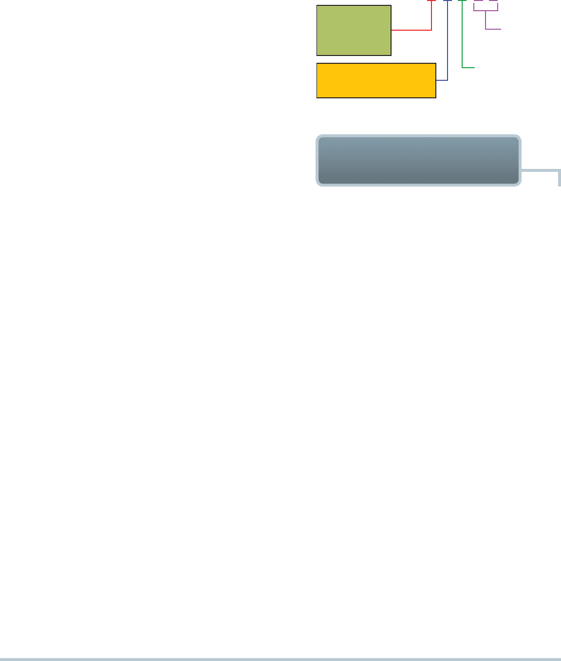
EXAMPLE: P0302 = CYLINDER #2 MISFIRE DETECTED
0 - GENERIC (SAE)
1 - MANUFACTURER SPECIFIC
SPECIFIC VEHICLE
SYSTEM
SPECIFIC FAUL
T
DESIGNATION
2030P
B - BODY
C - CHASSIS
P - POWERTRAIN
U - NETWORK
FIGURE 11–2 OBD-II DTC identification format.
A scan tool is required to retrieve DTCs from an OBD-II vehicle.
Every OBD-II scan tool will be able to read all generic Society
of Automotive Engineers (SAE) DTCs from any vehicle.
SEE
FIGURE 11–2 for definitions and explanations of OBD alphanu-
meric DTCs. The diagnostic trouble codes (DTCs) are grouped
into major categories, depending on the location of the fault on
the system involved:
Pxxx codes—powertrain DTCs (engine, transmission-
related faults)
Bxxx codes—body DTCs (accessories, interior-related
faults)
Cxxx codes—chassis DTCs (suspension and steering-
related faults)
Uxxx codes—network DTCs (module communication-
related faults)
DTC NUMBERING EXPLANATION The number in the
hundredth position indicates the specific vehicle system or sub-
group that failed. This position should be consistent for P0xxx
and P1xxx type codes. The following numbers and systems
were established by SAE:
P0100—Air metering and fuel system fault
P0200—Fuel system (fuel injector only) fault
P0300—Ignition system or misfire fault
P0400—Emission control system fault
P0500—Idle speed control, vehicle speed (VS) sensor fault
P0600—Computer output circuit (relay, solenoid, etc.) fault
P0700—Transaxle, transmission faults
NOTE: The tens and ones numbers indicate the part of
the system at fault.
TYPES OF DTCS Not all OBD-II DTCs are of the same
importance for exhaust emissions. Each type of DTC has differ-
ent requirements for it to set, and the computer will turn on the
MIL only for emissions-related DTCs.
OBD-II DTC NUMBERING
DESIGNATION
158 CHAPTER 11
Engine coolant temperature
Intake manifold pressure
Closed-open-loop status
Fault code that triggered the freeze-frame
If a misfire code is set, identify which cylinder is misfiring
A DTC should not be cleared from the vehicle computer mem-
ory unless the fault has been corrected and the technician is
so directed by the diagnostic procedure. If the problem that
caused the DTC to be set has been corrected, the computer will
automatically clear the DTC after 40 consecutive warm-up cy-
cles with no further faults detected (misfire and excessively rich
or lean condition codes require 80 warm-up cycles). The codes
can also be erased by using a scan tool.
SEE CHART 11–1 .
NOTE: Disconnecting the battery may not erase
OBD-II DTCs or freeze-frame data. Most vehicle manu-
facturers recommend using a scan tool to erase DTCs
rather than disconnecting the battery because the mem-
ory for the radio, seats, and learned engine operating
parameters is lost if the battery is disconnected.
TYPE A CODES A type A DTC is emission related and will cause
the MIL to be turned on the first trip if the computer has
detected a problem. Engine misfire or a very rich or lean air–fuel
ratio, for example, would cause a type A DTC. These codes alert
the driver to an emission problem that may cause damage to
the catalytic converter.
TYPE B CODES A type B code will be stored, and the MIL will be
turned on during the second consecutive trip, alerting the driver
to the fact that a diagnostic test was performed and failed.
NOTE: Type A and B codes are emission-related codes
that will cause the lighting of the malfunction indicator
lamp (MIL), usually labeled “check engine” or “service
engine soon.”
TYPE C AND D CODES Type C and D codes are for use with non–
emission-related diagnostic tests; they will cause the lighting of a
“service” lamp (if the vehicle is so equipped). Type C codes are also
called type C1 codes, and D codes are also called type C0 codes.
DIAGNOSTIC TROUBLE CODE PRIORITY CARB has
also mandated that all diagnostic trouble codes (DTCs) be
stored according to individual priority. DTCs with a higher
priority overwrite those with a lower priority. The OBD-II System
DTC Priority is listed here:
Priority 0—Non–emission-related codes
Priority 1—One-trip failure of two-trip fault for non fuel,
non misfire codes
Priority 2—One-trip failure of two-trip fault for fuel or
misfire codes
Priority 3—Two-trip failure or matured fault of non fuel,
non misfire codes
Priority 4—Two-trip failure or matured fault for fuel or
misfire codes
OBD-II FREEZE-FRAME
To assist the service technician, OBD II requires the computer to take
a “snapshot” or freeze-frame of all data at the instant an emission-
related DTC is set. A scan tool is required to retrieve this data.
NOTE: Although OBD-II requires that just one freeze-
frame of data be stored, the instant an emission-related
DTC is set, vehicle manufacturers usually provide ex-
panded data about the DTC beyond that required such
as General Motors’s failure recorders. However, retriev-
ing this enhanced data usually requires the use of the
vehicle-specific scan tool.
Freeze-frame items include the following:
Calculated load value
Engine speed (RPM)
Short-term and long-term fuel trim percent
Fuel system pressure (on some vehicles)
Vehicle speed (mph)
These are the exact engine operating conditions required for a
diagnostic monitor to run:
Example:
Specific RPM
Specific ECT, MAP, run time, etc.
PENDING Under some situations the PCM will not run a
monitor if the MIL is illuminated and a fault is stored from
another monitor. In these situations, the PCM postpones moni-
tors pending a resolution of the original fault. The PCM does not
run the test until the problem is remedied.
For example, when the MIL is illuminated for an oxygen
sensor fault, the PCM does not run the catalyst monitor until
the oxygen sensor fault is remedied. Since the catalyst monitor
is based on signals from the oxygen sensor, running the test
would produce inaccurate results.
ENABLING CONDITIONS
What Are Pending Codes?
Pending codes are set when operating conditions are
met and the component or circuit is not within the
normal range yet the conditions have not yet been met
to set a DTC. For example, a sensor may require two
consecutive faults before a DTC is set. If a scan tool
displays a pending code or a failure, a driveability con-
cern could also be present. The pending code can help
the technician to determine the root cause before the
customer complains of a check engine light indication.
?
FREQUENTLY ASKED QUESTION
ON-BOARD DIAGNOSIS 159
CHART 11–1
PCM Determination of Faults Chart
MONITOR
NAME
MONITOR TYPE
(HOW OFTEN IT
COMPLETES)
NUMBER OF
FAULTS ON
SEPARATE
TRIPS TO SET A
PENDING DTC
NUMBER OF
SEPARATE
CONSECUTIVE
TRIPS TO LIGHT
MIL, STORE A DTC
NUMBER OF
TRIPS WITH
NO FAULTS
TO ERASE A
MATURING DTC
NUMBER OF TRIPS
WITH NO FAULT TO
TURN THE MIL OFF
NUMBER OF
WARM-UP
CYCLES TO ERASE
DTC AFTER MIL IS
TURNED OFF
CCM Continuous (when
trip conditions
allow it)
1 2 1 3–Trips 40
Catalyst Once per drive
cycle
1 3 1 3–OBD-II drive cycle 40
Misfire type A Continuous 1 3–Similar conditions 80
Misfire type B Continuous 1 2 1 3–Similar conditions 80
Fuel system Continuous 1 2 1 3–Similar conditions 80
Oxygen sensor Once per trip 1 2 1 3–Trips 40
EGR Once per trip 1 2 1 3–Trips 40
EVAP Once per trip 1 1 1 3–Trips 40
AIR Once per trip 1 2 1 3–Trips 40
CONFLICT There are also situations when the PCM does
not run a monitor if another monitor is in progress. In these situ-
ations, the effects of another monitor running could result in an
erroneous failure. If this conflict is present, the monitor is not run
until the conflicting condition passes. Most likely, the monitor
will run later after the conflicting monitor has passed.
For example, if the fuel system monitor is in progress, the
PCM does not run the EGR monitor. Since both tests monitor
changes in air–fuel ratio and adaptive fuel compensation, the
monitors conflict with each other.
SUSPEND Occasionally, the PCM may not allow a two-trip fault
to mature. The PCM will suspend the maturing fault if a condition
exists that may induce erroneous failure. This prevents illuminating
the MIL for the wrong fault and allows more precise diagnosis.
For example, if the PCM is storing a one-trip fault for the oxy-
gen sensor and the EGR monitor, the PCM may still run the EGR
monitor but will suspend the results until the oxygen sensor moni-
tor either passes or fails. At that point, the PCM can determine if
the EGR system is actually failing or if an oxygen sensor is failing.
PCM TESTS
RATIONALITY TEST While input signals to the PCM are
constantly being monitored for electrical opens and shorts, they
are also tested for rationality. This means that the input signal
is compared against other inputs and information to see if it
makes sense under the current conditions.
PCM sensor inputs that are checked for rationality include
the following:
MAP sensor
O
2
sensor
ECT
Camshaft position sensor (CMP)
VS sensor
Crankshaft position sensor (CKP)
IAT sensor
TP sensor
Ambient air temperature sensor
Power steering switch
O
2
sensor heater
Engine controller
Brake switch
P/N switch (range switch)
Transmission controls
FUNCTIONALITY TEST A functionality test refers to PCM
inputs checking the operation of the outputs:
Example:
PCM commands IAC to increase engine speed
PCM monitors engine RPM
Functionality test fails if engine speed does not increase
PCM outputs that are checked for functionality include the
following:
EVAP canister purge solenoid
EVAP purge vent solenoid
Cooling fan
Idle air control solenoid
Ignition control system
Transmission torque converter clutch solenoid
Transmission shift solenoids (A, B, 1–2, etc.)

160 CHAPTER 11
Mode Four Clear and reset diagnostic trouble codes
(DTCs), freeze-frame data, and readiness sta-
tus monitors for noncontinuous monitors only
Mode Five Oxygen sensor monitor test results
Mode Six Onboard monitoring of test results for non-
continuously monitored systems
Mode Seven Onboard monitoring of test results for con-
tinuously monitored systems
Mode Eight Bidirectional control of onboard systems
Mode Nine Module identification
The global (generic) data is used by most state emission
programs. Global OBD-II displays often use hexadecimal num-
bers, which use 16 numbers instead of 10. The numbers 0 to 9
(zero counts as a number) make up the first 10 and then capital
letters A to F complete the 16 numbers. To help identify the
number as being in a hexadecimal format, a dollar sign ($) is
used in front of the number or letter. See the following conver-
sion chart:
Decimal Number Hexadecimal Code
0 $0
1 $1
2 $2
3 $3
4 $4
5 $5
6 $6
7 $7
8 $8
9 $9
10 $A
11 $B
12 $C
13 $D
14 $E
15 $F
Hexadecimal coding is also used to identify tests ( test
identification [TID] and component identification [CID] ).
ELECTRICAL TEST Refers to the PCM check of both input
and outputs for the following:
Open
Shorts
Ground
Example:
ECT
Shorted high (input to PCM) above capable voltage; that is,
5-volt sensor with 12-volt input to PCM would indicate a short
to voltage.
Monitor
Type
Conditions
to Set
DTC and
Illuminate
MIL
Extinguish
MIL
Clear DTC
Criteria
Applicable
DTC
Conti nuous
1-trip
monitor
(See note
below)
Input and
output
failure—
rationally,
functionally,
electrically
3 con-
secutive
pass trips
40 warm-
up cycles
P0123
NOTE: The number of times the comprehensive compo-
nent monitor must detect a fault depends on the vehicle
manufacturer. On some vehicles, the comprehensive
component monitor will activate the MIL as soon as it
detects a fault. On other vehicles, the comprehensive
component monitor must fail two times in a row.
Freeze-frame captured on first-trip failure.
Enabling conditions: Many PCM sensors and output
devices are tested at key-on or immediately after engine
start-up. However, some devices (ECT, idle speed control)
are tested by the CCM only after the engine meets par-
ticular engine conditions.
Pending: No pending condition
Conflict: No conflict conditions
Suspend: No suspend conditions
GLOBAL OBD-II
All OBD-II vehicles must be able to display data on a global (also
called generic ) scan tool under nine different modes of opera-
tion. These modes include the following:
Mode One Current power train data ( parameter identi-
fication display or PID )
Mode Two Freeze-frame data
Mode Three Diagnostic trouble codes
How Can You Tell Generic from Factory?
When using a scan tool on an OBD-II-equipped
vehicle, if the display asks for make, model, and
year, then the factory or enhanced part of the PCM
is being accessed. If the generic or global part of
the PCM is being scanned, then there is no need to
know the vehicle identification details.
?
FREQUENTLY ASKED QUESTION