Halderman J.D., Linder J. Automotive Fuel and Emissions Control Systems
Подождите немного. Документ загружается.

CAN AND NETWORK COMMUNICATIONS 171
CAN H
(3.5 V)
CAN L
(1.5 V)
VOLTAGE
3.5 V
2.5 V
1.5 V
INACTIVE
(RECESSIVE)
ACTIVE
(DOMINANT)
TIME
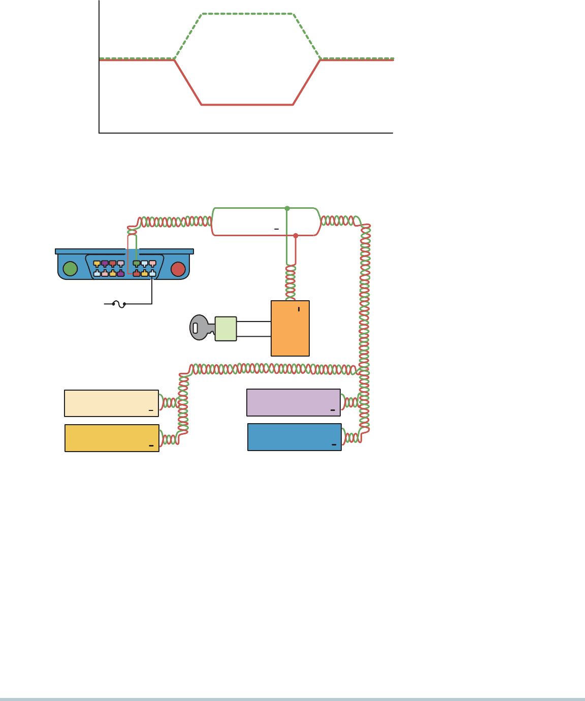
FIGURE 12–19 CAN uses a differential
type of module communication where
the voltage on one wire is the equal but
opposite voltage on the other wire. When
no communication is occurring, both wires
have 2.5 volts applied. When communica-
tion is occurring, CAN H (high) goes up
1 volt to 3.5 volts, and CAN L (low) goes
down 1 volt to 1.5 volts.
CAN BUS (+)
CAN BUS ( )
CCD ( )
CCD (+)
INSTRUMENT
CLUSTER
CCD ( )
CCD (+)
CCD ( )
CCD (+)
CCD ( )
CCD (+)
16
B+
14
6
CAN BUS (+)
CAN BUS ( )
IMMOBILIZER
MODULE
TRANSPONDER
KEY
NODE 3
NODE 4
NODE 5
FIGURE 12–20 A typical (generic) system
showing how the CAN BUS is connected
to various electrical accessories and systems
in thevehicle.
CAN A. This class operates on only one wire at slow
speeds and is therefore less expensive to build. CAN A
operates a data transfer rate of 33.33 Kbs in normal mode
and up to 83.33 Kbs during reprogramming mode. CAN A
uses the vehicle ground as the signal return circuit.
CAN B. This class operates on a two-wire network and
does not use the vehicle ground as the signal return
circuit. CAN B uses a data transfer rate of 95.2 Kbs. In-
stead, CAN B (and CAN C) uses two network wires for
differential signaling. This means that the two data signal
voltages are opposite to each other and used for error
detection by constantly being compared. In this case,
when the signal voltage at one of the CAN data wires
goes high (CAN H), the other one goes low (CAN L), hence
the name differential signaling . Differential signaling is
also used for redundancy in case one of the signal wires
shorts out.
CAN C. This class is the highest speed CAN protocol
with speeds up to 500 Kbs. Beginning with 2008 models,
all vehicles sold in the United States must use CAN BUS
for scan tool communications. Most vehicle manufactur-
ers started using CAN in older models, and it is easy to
determine if a vehicle is equipped with CAN. The CAN
BUS communicates to the scan tool through terminals 6
and 14 of the DLC, indicating that the vehicle is equipped
with CAN.
SEE FIGURE 12–20 .
The total voltage remains constant at all times, and the
electromagnetic field effects of the two data BUS lines cancel
each other out. The data BUS line is protected against received
radiation and is virtually neutral in sending radiation.
172 CHAPTER 12
4
10
14 16
5
7
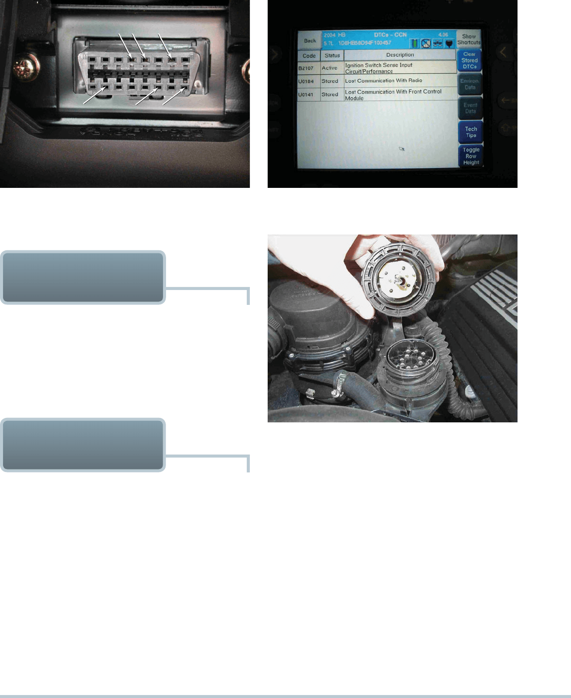
FIGURE 12–21 A DLC from a pre-CAN Acura. It shows
terminals in cavities 4, 5 (grounds), 7, 10, 14, and 16 (B).
FIGURE 12–22 A Honda scan display showing a B and two
U codes, all indicating a BUS-related problem(s).
HONDA/TOYOTA
COMMUNICATIONS
The primary BUS communications on pre-CAN-equipped ve-
hicles is ISO 9141-2 using terminals 7 and 15 at the OBD-II DLC.
SEE FIGURE 12–21 .
A factory scan tool or an aftermarket scan tool equipped
with enhanced original equipment (OE) software is needed to
access many of the BUS messages.
SEE FIGURE 12–22 .
EUROPEAN BUS
COMMUNICATIONS
UNIQUE DIAGNOSTIC CONNECTOR Many different types
of module communications protocols are used on European
vehicles such as Mercedes and BMW.
Most of these communication BUS messages cannot be
accessed through the data link connector (DLC). To check the
operation of the individual modules, a scan tool equipped with
factory-type software will be needed to communicate with the
module through the gateway module.
SEE FIGURE 12–23 for
an alternative access method to the modules.
MEDIA ORIENTED SYSTEM TRANSPORT BUS The
media-oriented system transport (MOST) BUS uses fiber optics
for module-to-module communications in a ring or star configu-
ration. This BUS system is currently being used for entertain-
ment equipment data communications for videos, CDs, and
other media systems in the vehicle.
FIGURE 12–23 A typical 38-cavity diagnostic connector as
found on many BMW and Mercedes vehicles under the hood.
The use of a breakout box (BOB) connected to this connector
can often be used to gain access to module BUS information.
MOTOROLA INTERCONNECT BUS Motorola intercon-
nect (MI) is a single-wire serial communications protocol, using
one master control module and many slave modules. Typical
application of the MI BUS protocol is with power and memory
mirrors, seats, windows, and headlight levelers.
DISTRIBUTED SYSTEM INTERFACE BUS Distributed
system interface (DSI) BUS protocol was developed by Motorola
and uses a two-wire serial BUS. This BUS protocol is currently
being used for safety-related sensors and components.
BOSCH-SIEMANS-TEMIC BUS The Bosch-Siemans-
Temic (BST) BUS is another system that is used for safety-related
components and sensors in a vehicle, such as airbags. The BST
BUS is a two-wire system and operates up to 250,000 bps.
CAN AND NETWORK COMMUNICATIONS 173
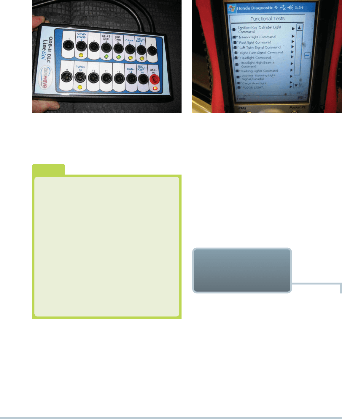
FIGURE 12–24 A breakout box (BOB) used to access the
BUS terminals while using a scan tool to activate the modules.
This breakout box is equipped with LEDs that light when
circuits are active.
BYTEFLIGHT BUS The byteflight BUS is used in safety
critical systems, such as airbags, and uses the time division
multiple access (TDMA) protocol, which operates at 10 million
bps using a plastic optical fiber (POF).
FLEXRAY BUS FlexRay BUS is a version of byteflight and
is a high-speed serial communication system for in-vehicle
networks. FlexRay is commonly used for steer-by-wire and
brake-by-wire systems.
How Do You Know What System Is Used?
Use service information to determine which network
communication protocol is used. However, because
of the various systems on some vehicles, it may be
easier to look at the data link connection to deter-
mine the system. All OBD-II vehicles have terminals
in the following cavities:
Terminal 4: chassis ground
Terminal 5: computer (signal) ground
Terminal 16: 12 V positive
The terminals in cavities 6 and 14 mean that
this vehicle is equipped with CAN as the only module
communication protocol available at the DLC. To
perform a test of the BUS, use a breakout box (BOB)
to gain access to the terminals while connecting to
the vehicle, using a scan tool.
SEE FIGURE 12–24
or a typical OBD-II connector breakout box.
?
FREQUENTLY ASKED QUESTION
STEPS TO FINDING A FAULT When a network commu-
nications fault is suspected, perform the following steps:
STEP 1 Check everything that does and does not work.
Often accessories that do not seem to be connected
can help identify which module or BUS circuit is atfault.
STEP 2 Perform module status test. Use a factory-level scan
tool or an aftermarket scan tool equipped with en-
hanced software that allows OE-like functions. Check
if the components or systems can be operated through
the scan tool.
SEE FIGURE 12–25 .
Ping modules. Start the Class 2 diagnosis by us-
ing a scan tool and select diagnostic circuit check .
If no diagnostic trouble codes (DTCs) are shown,
there could be a communication problem. Select
NETWORK
COMMUNICATIONS
DIAGNOSIS
FIGURE 12–25 This Honda scan tool allows the technician
to turn on individual lights and operate individual power
windows and other accessories that are connected to the
BUS system.
DOMESTIC DIGITAL BUS The domestic digital BUS,
commonly designated D2B, is an optical BUS system connect-
ing audio, video, computer, and telephone components in a
single-ring structure with a speed of up to 5,600,000 bps.
LOCAL INTERCONNECT NETWORK BUS Local inter-
connect network (LIN) is a BUS protocol used between intelligent
sensors and actuators and has a BUS speed of 19,200 bps.
174 CHAPTER 12
No Communication? Try Bypass Mode.
If a Tech 2 scan tool shows “no communication,” try
using the bypass mode to see what should be on the
data display. To enter bypass mode, perform the fol-
lowing steps:
STEP 1 Select tool option (F3).
STEP 2 Set communications to bypass (F5).
STEP 3 Select enable.
STEP 4 Input make/model and year of vehicle.
STEP 5 Note all parameters that should be included,
as shown. The values will not be shown.
TECH TIP
message monitor, which will display the status of
all of the modules on the Class 2 BUS circuit. The
modules that are awake will be shown as active
and the scan tool can be used to ping individual
modules or command all modules. The ping com-
mand should change the status from “active” to
“inactive.”
SEE FIGURE 12–26 .
NOTE: If an excessive parasitic draw is being diag-
nosed, use a scan tool to ping the modules in one way
to determine if one of the modules is not going to sleep
and causing the excessive battery drain.
Check state of health. All modules on the Class 2
BUS circuit have at least one other module responsible
for reporting state of health (SOH). If a module fails to
send a state of health message within five seconds, the
companion module will set a diagnostic trouble code
for the module that did not respond. The defective
module is not capable of sending this message.
Class 2 Message Monitor
Sleep
Mode
Ping
Module
Ping All
Modules
Modules
Status
BCM/BFC/DIM/SBM/TBC
PCM/VCM
ABS/TCS
IPC
SIR
Radio
ACM/HCM
00:00:03 1 / 9
BCM/BFC/DIM/SBM/TBC
Active
Active
Active
Active
Active
Active
Active
1
1
1
1
1
1
1
FIGURE 12–26 Modules used in a General Motors vehicle
can be “pinged” using a Tech 2 scan tool.
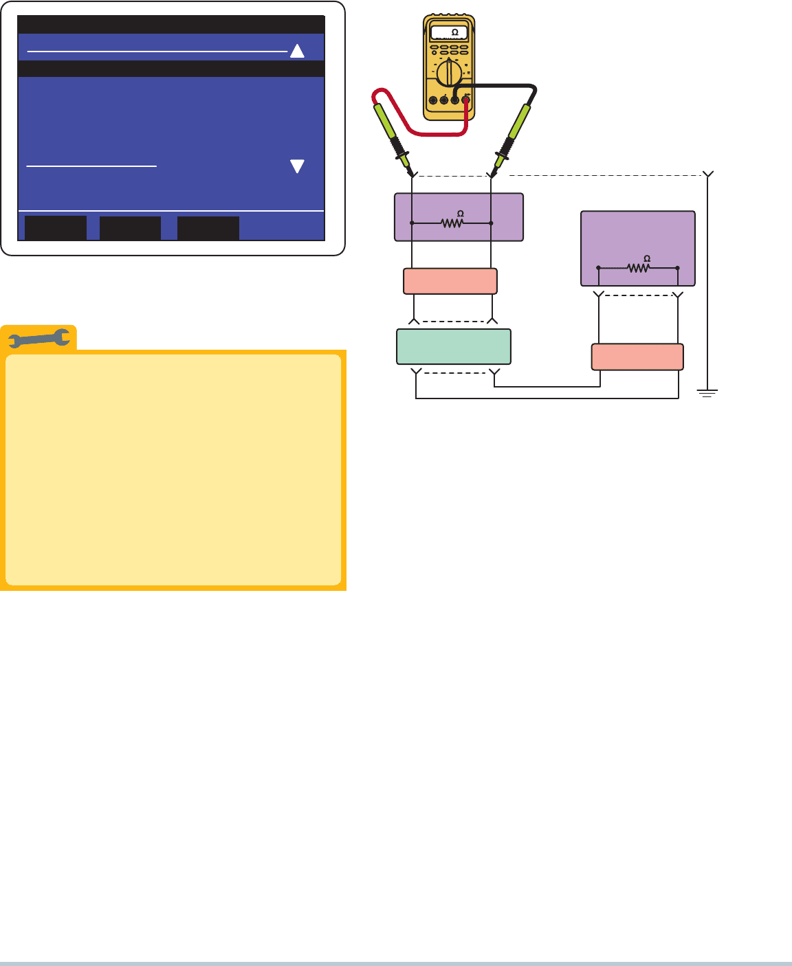
STEP 3 Check the resistance of the terminating resistors.
Most high-speed BUS systems use resistors at each
end, called terminating resistors. These resistors are
used to help reduce interference into other systems in
the vehicle. Usually two 120-ohm resistors are installed
at each end and are therefore connected electrically in
parallel. Two 120-ohm resistors connected in paral-
lel would measure 60 ohms if being tested using an
ohmmeter.
SEE FIGURE 12–27 .
STEP 4 Check data BUS for voltages. Use a digital multi-
meter set to DC volts to monitor communications and
check the BUS for proper operation. Some BUS condi-
tions and possible causes include the following:
Signal is zero volt all of the time. Check for short-
to-ground by unplugging modules one at a time to
check if one module is causing the problem.
Signal is high or 12 volts all of the time. The BUS
circuit could be shorted to 12 V. Check with the
customer to see if any service or body repair work
was done recently. Try unplugging each module one
at a time to pin down which module is causing the
communications problem.
A variable voltage usually indicates that messages
are being sent and received. CAN and Class 2 can be
identified by looking at the data link connector (DLC) for
a terminal in cavity number 2. Class 2 is active all of the
time the ignition is on, and therefore voltage variation
between 0 and 7 V can be measured using a DMM set
to read DC volts.
SEE FIGURE 12–28 .
COM
A
mA A
mV
V
V
mA
A
A
V
DIGITAL MULTIMETER
RECORD
MAX MIN
HZ
%
10
2
345
6
7
8
9
0
HZ
MAXMIN
120
TERMINATOR
VCIM
PSCM
14 6
VCIM
120
TERMINATOR
PCM
BCM
60
OHMMETER
FIGURE 12–27 Checking the terminating resistors using an
ohmmeter at the DLC.
CAN AND NETWORK COMMUNICATIONS 175
FIGURE 12–28 Use front-probe terminals to access the data
link connector. Always follow the specified back-probe and
front-probe procedures as found in service information.
STEP 5 Use a digital storage oscilloscope to monitor the
waveforms of the BUS circuit. Using a scope on the
data line terminals can show if communication is being
transmitted. Typical faults and their causes include the
following:
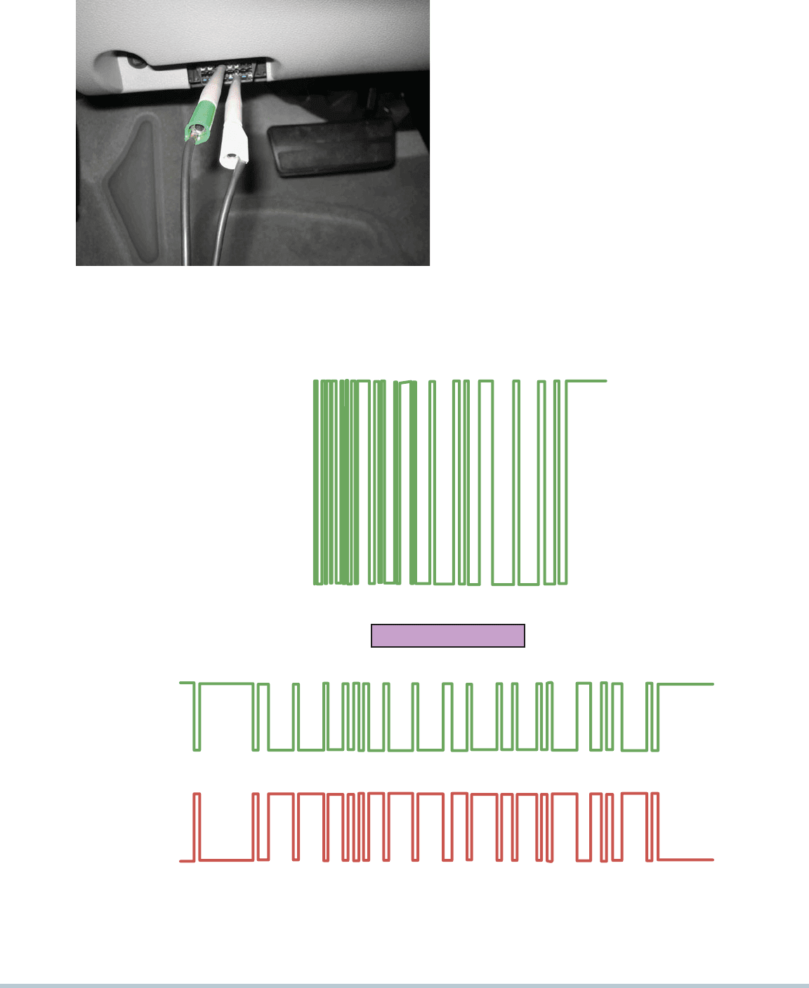
Normal operation. Normal operation shows vari-
able voltage signals on the data lines. It is impos-
sible to know what information is being transmitted,
but if there is activity with short sections of inactivity,
this indicates normal data line transmission activity.
SEE FIGURE 12–29 .
High voltage. If there is a constant high-voltage
signal without any change, this indicates that the
data line is shorted to voltage.
Zero or low voltage. If the data line voltage is zero
or almost zero and not showing any higher voltage
signals, then the data line is short-to-ground.
STEP 6 Follow factory service information instructions to
isolate the cause of the fault. This step often involves
disconnecting one module at a time to see if it is the
cause of a short-to-ground or an open in the BUS circuit.
FIGURE 12–29 (a) Data is sent in packets, so it is normal to see activity then a flat line between messages. (b) A CAN BUS
should show voltages that are opposite when there is normal communications. CAN H (high) circuit should go from 2.5 volts at
rest to 3.5 volts when active. The CAN L (low) circuit goes from 2.5volts at rest to 1.5 volts when active.
LOW
HIGH
(a)
CAN LOW
CAN HIGH
CAN BUS LOOKS GOOD
(b)

176 CHAPTER 12
The Radio Caused No-Start Story
A 2005 Chevrolet Cobalt did not start. A technician
checked with a subscription-based helpline service and
discovered that a fault with the Class 2 data circuit could
prevent the engine from starting. The advisor suggested
that a module should be disconnected one at a time to
see if one of them was taking the data line to ground.
The two most common components on the Class 2
serial data line that have been known to cause a lack of
communication and become shorted-to-ground are the
radio and electronic brake control module (EBCM). The
first one the technician disconnected was the radio. The
engine started and ran. Apparently the Class 2 serial
data line was shorted-to-ground inside the radio, which
took the entire BUS down. When BUS communication
is lost, the PCM is not able to energize the fuel pump,
ignition, or fuel injectors so the engine would not start.
The radio was replaced to solve the no-start condition.
REAL WORLD FIX
OBD-II DATA LINK
CONNECTOR
All OBD-II vehicles use a 16-pin connector that includes the
following:
Pin 4 chassis ground
Pin 5 signal ground
Pin 16 battery power (4 A max)
SEE FIGURE 12–30 .
GENERAL MOTORS VEHICLES
SAE J-1850 (VPW, Class 2, 10.4 Kbs) standard, which
uses pins 2, 4, 5, and 16 but not 10
1
9
10 11
12 13 14 15
16
8
76
5
43
2
OBD-II DLC
PIN
NO.
1.
2.
3.
4.
5.
6.
7.
8.
9.
10.
11.
12.
13.
14.
15.
16.
ASSIGNMENTS
MANUFACTURER'S DISCRETION
BUS + LINE, SAE J1850
MANUFACTURER'S DISCRETION
CHASSIS GROUND
SIGNAL GROUND
MANUFACTURER'S DISCRETION
K LINE, ISO 9141
MANUFACTURER'S DISCRETION
MANUFACTURER'S DISCRETION
BUS – LINE, SAE J1850
MANUFACTURER'S DISCRETION
MANUFACTURER'S DISCRETION
MANUFACTURER'S DISCRETION
MANUFACTURER'S DISCRETION
L LINE, ISO 9141
VEHICLE BATTERY POSITIVE
(4A MAX)
FIGURE 12–30 A 16-pin OBD-II DLC with terminals identi-
fied. Scan tools use the power pin (16) and ground pin (4) for
power so that a separate cigarette lighter plug is not neces-
sary on OBD-II vehicles.
Which Module Is the Gateway Module?
The gateway module is responsible for communicating
with other modules and acts as the main commu-
nications module for scan tool data. Most General
Motors vehicles use the body control module (BCM)
or the instrument panel control (IPC) module as the
gateway. To verify which module is the gateway,
check the schematic and look for one that has voltage
applied during all of the following conditions:
•
Key on, engine off
•
Engine cranking
•
Engine running
?
FREQUENTLY ASKED QUESTION
GM Domestic OBD-II
Pin 1 and 9: CCM (comprehensive component monitor)
slow baud rate, 8,192 UART
Pins 2 and 10: OEM enhanced, fast rate, 40,500 baud rate
Pins 7 and 15: generic OBD-II, ISO 9141, 10,400 baud rate
Pins 6 and 14: GMLAN
ASIAN, CHRYSLER, AND EUROPEAN VEHICLES
ISO 9141-2 standard, which uses pins 4, 5, 7, 15, and 16
Chrysler Domestic Group OBD-II
Pins 2 and 10: CCM
Pins 3 and 14: OEM enhanced, 60,500 baud rate
Pins 7 and 15: generic OBD-II, ISO 9141, 10,400 baud rate
FORD VEHICLES
SAE J-1850 (PWM, 41.6 Kbs) standard, which uses pins
2, 4, 5, 10, and 16
Ford Domestic OBD-II
Pins 2 and 10: CCM
Pins 6 and 14: OEM enhanced, Class C, 40,500 baud rate
Pins 7 and 15: generic OBD-II, ISO 9141, 10,400 baud rate
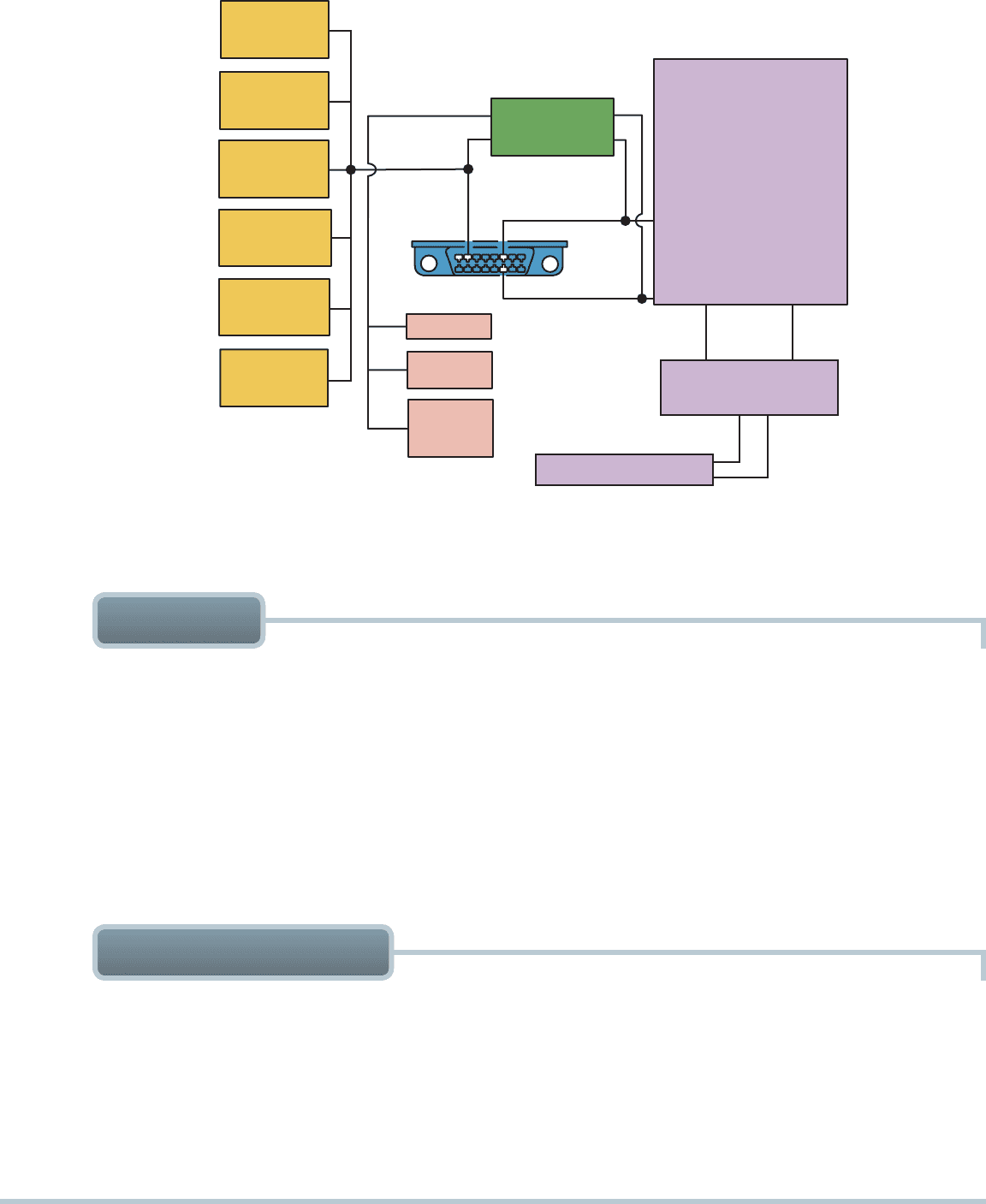
Check Computer Data Line Circuit Schematic
Many General Motors vehicles use more than one
type of BUS communications protocol. Check service
information (SI) and look at the schematic for com-
puter data line circuits, which should show all of the
data BUSes and their connectors to the diagnostic
link connector (DLC).
SEE FIGURE 12–31 .
TECH TIP
CAN AND NETWORK COMMUNICATIONS 177
SENSING
DIAGNOSTIC
MODULE (SDM)
ELECTRONIC BRAKE/
TRACTION CONTROL
(EBTCM)
CLASS 2
BODY CONTROL
MODULE (BCM)
GATEWAY
HVAC
CONTROL
MODULE
INSTRUMENT
PANEL
CLUSTER
(4) DOOR
MODULES
MEMORY
SEAT
MODULE
NAVIGATION
RADIO
RADIO
HEADS-UP
DISPLAY
(HUD)
VCI
MODULE
2
6
14
LOW SPEED
GMLAN
TRANSMISSION
CONTROL MODULE
(TCM)
POWERTRAIN CONTROL
MODULE (ECM)
HIGH SPEED
GMLAN
VEHICLE
COMMUNICATIONS
INTERFACE MODULE
(VCIM)
THROTTLE ACTUATOR
UART DATA 1UART DATA 2
FIGURE 12–31 This schematic of a Chevrolet Equinox shows that the vehicle uses a GMLAN BUS (DLC pins 6 and 14), plus a
Class 2 (pin 2) and UART.
5. Types of module communications used on Ford vehicles
include SCP, UBP, and CAN.
6. Chrysler brand vehicles use SCI, CCD, PCI, and CAN com-
munications protocols.
7. Many European vehicles use an underhood electrical con-
nector that can be used to access electrical components
and modules using a breakout box (BOB) or special tester.
8. Diagnosis of network communications includes checking
the terminating resistors and checking for changing voltage
signals at the DLC.
1. The use of a network for module communications reduces
the number of wires and connections needed.
2. Module communication configurations include ring link,
star link, and ring/star hybrid systems.
3. The SAE communication classifications for vehicle com-
munications systems include Class A (low speed), Class B
(medium speed), and Class C (high speed).
4. Various module communications used on General Motors
vehicles include UART, E & C, Class 2, keyword communi-
cations, and GMLAN (CAN).
SUMMARY
3. Why is a gateway module used?
4. What are U codes?
1. Why is a communication network used?
2. Why are the two wires twisted if used for network
communications?
REVIEW QUESTIONS

178 CHAPTER 12
7. GMLAN is the General Motors term for which type of
module communication?
a. UART c. High-speed CAN
b. Class 2 d. Keyword 2000
8. CAN H and CAN L operate how?
a. CAN H is at 2.5 volts when not transmitting.
b. CAN L is at 2.5 volts when not transmitting.
c. CAN H goes to 3.5 volts when transmitting.
d. All of the above
9. Which terminal of the OBD-II data link connector is the
signal ground for all vehicles?
a. 1 c. 4
b. 3 d. 5
10. Terminal 16 of the OBD-II data link connector is used for
what?
a. Chassis ground
b. 12 V positive
c. Module (signal ground)
d. Manufacturer’s discretion
1. Technician A says that module communications networks
are used to reduce the number of wires in a vehicle. Tech-
nician B says that a communications network is used to
share data from sensors, which can be used by many
different modules. Which technician is correct?
a. Technician A only
b. Technician B only
c. Both Technicians A and B
d.
Neither Technician A nor B
2. A module is also known as a ________ .
a. BUS c. Terminator
b. Node d. Resistor pack
3. A high-speed CAN BUS communicates with a scan tool
through which terminal(s)?
a. 6 and 14 c. 7 and 15
b. 2 d. 4 and 16
4. UART uses a(n) ________ signal that toggles 0 V.
a. 5-V c. 8-V
b. 7-V d. 12-V
5. GM Class 2 communication toggles between ________ .
a. 5 and 7 V c. 7 and 12 V
b. 0 and 12 V d. 0 and 7 V
6. Which terminal of the data link connector does General
Motors use for Class 2 communication?
a. 1 c. 3
b. 2 d. 4
CHAPTER QUIZ
TEMPERATURE SENSORS 179
chapter
TEMPERATURE
SENSORS
13
OBJECTIVES: After studying Chapter 13 , the reader should be able to: • Prepare for ASE Engine Performance (A8)
certification test content area “E” (Computerized Engine Controls Diagnosis and Repair). • Explain the purpose and function of
the ECT and IAT temperature sensors. • Describe how to test temperature sensors. • Discuss how automatic fluid temperature
sensor values can affect transmission operation.
KEY TERMS: Cylinder head temperature (CHT) 187 • Engine coolant temperature (ECT) 179 • Engine fuel temperature
(EFT) 187 • Negative temperature coefficient (NTC) 179 • Throttle-body temperature (TBT) 185 • Transmission fluid
temperature (TFT) 186
ENGINE COOLANT
TEMPERATURE
SENSOR
UPPER RADIATOR HOSE
THERMOSTAT
HOUSING
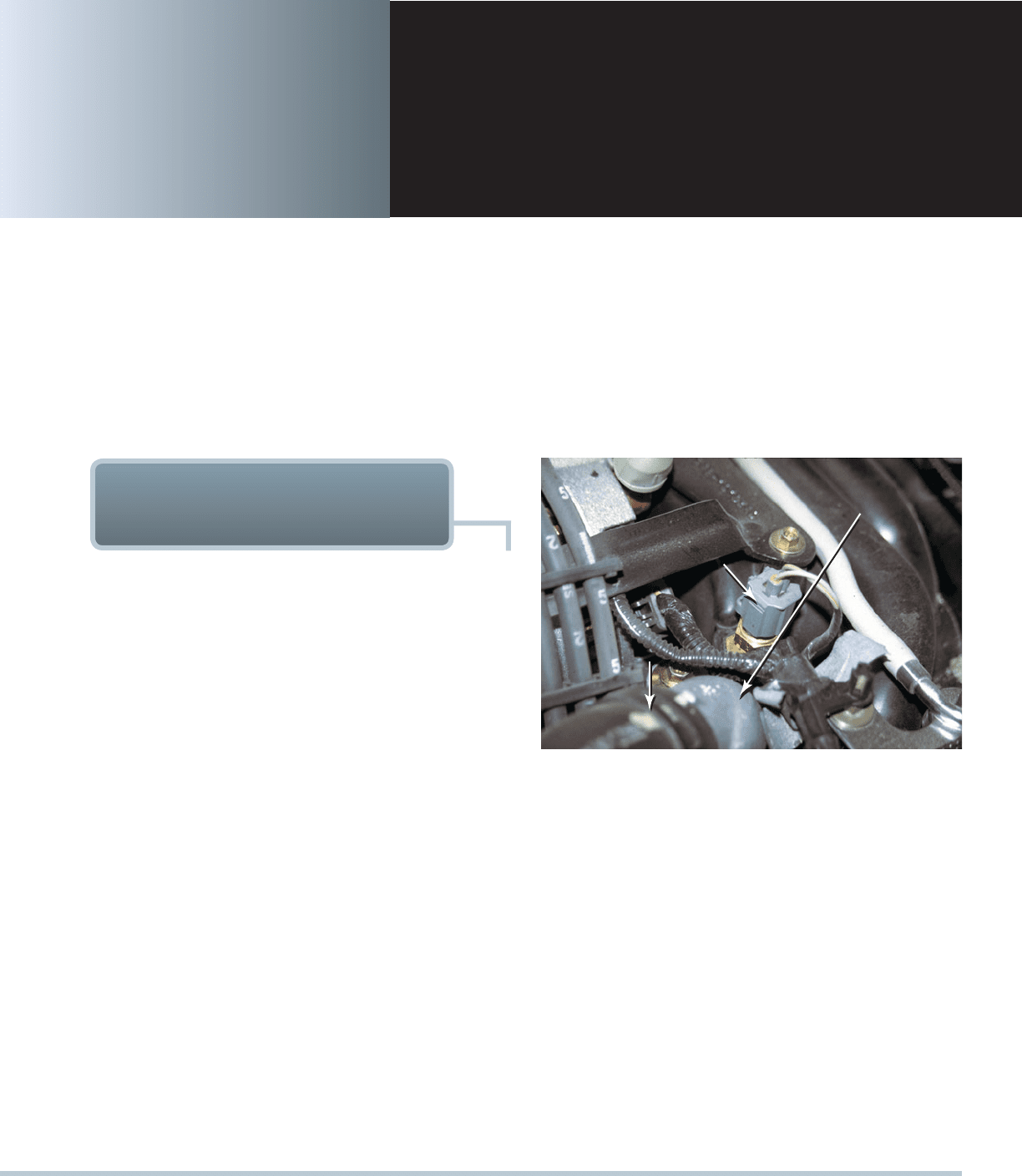
FIGURE 13–1 A typical engine coolant temperature (ECT)
sensor. ECT sensors are located near the thermostat housing
on most engines.
ENGINE COOLANT
TEMPERATURE SENSORS
PURPOSE AND FUNCTION Computer-equipped vehicles
use an engine coolant temperature (ECT) sensor. When the
engine is cold, the fuel mixture must be richer to prevent stalling
and engine stumble. When the engine is warm, the fuel mixture
can be leaner to provide maximum fuel economy with the lowest
possible exhaust emissions. Because the computer controls spark
timing and fuel mixture, it will need toknow the engine tempera-
ture. An engine coolant temperature (ECT) sensor screwed into
the engine coolant passage will provide the computer with this
information.
SEE FIGURE 13–1 . This will be the most important
(high-authority) sensor while the engine is cold. The ignition timing
can also be tailored to engine (coolant) temperature. A hot engine
cannot have the spark timing as far advanced as can a cold engine.
The ECT sensor is also used as an important input for the following:
Idle air control (IAC) position
Oxygen sensor closed-loop status
Canister purge on/off times
Idle speed
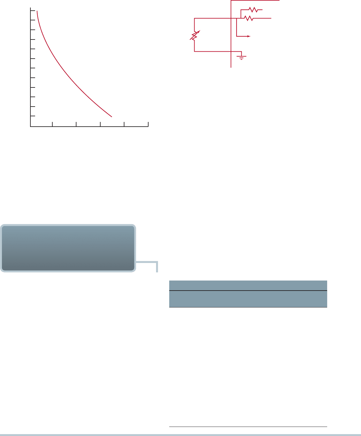
ECT SENSOR CONSTRUCTION Engine coolant tem-
perature sensors are constructed of a semiconductor material
that decreases in resistance as the temperature of the sensor
increases. Coolant sensors have very high resistance when the
coolant is cold and low resistance when the coolant is hot. This is
referred to as having a negative temperature coefficient (NTC),
which is opposite to the situation with most other electrical com-
ponents.
SEE FIGURE 13–2 . Therefore, if the coolant sensor
has a poor connection (high resistance) at the wiring connector,
the computer will supply a richer-than-normal fuel mixture based
on the resistance of the coolant sensor. Poor fuel economy and a
possible-rich code can be caused by a defective sensor or high
resistance in the sensor wiring. If the sensor was shorted or defec-
tive and had too low a resistance, a leaner-than-normal fuel mix-
ture would be supplied to the engine. A too-lean fuel mixture can
cause driveability problems and a possible-lean computer code.
STEPPED ECT CIRCUITS Some vehicle manufacturers
use a step-up resistor to effectively broaden the range of the
ECT sensor. Chrysler and General Motors vehicles use the same
sensor as a nonstepped ECT circuit but instead apply the sensor
voltage through two different resistors:
When the temperature is cold, usually below 120°F
(50°C), the ECT sensor voltage is applied through a
high-value resistor inside the PCM.
180 CHAPTER 13
PCM
300
3.5 K
ECT
SENSOR
5V (ABOVE 120°F [50°C])
5V (BELOW 120°F [50°C])
SENSOR INPUT
FIGURE 13–3 A typical two-step ECT circuit showing that
when the coolant temperature is low, the PCM applies a 5-volt
reference voltage to the ECT sensor through a higher resis-
tance compared to when the temperature is higher.
TEMPERATURE
°C
248°
0V 4V3V2V1V 5V
VOLTAGE READING (VOLTS)
°F
212°
176°
140°
104°
68°
32°
120°
100°
80°
60°
40°
20°
0°
FIGURE 13–2 A typical ECT sensor temperature versus
voltage curve.
When the temperature is warm, usually above 120°F (50°C),
the ECT sensor voltage is applied through a much lower
resistance value inside the PCM.
SEE FIGURE 13–3 .
The purpose of this extra circuit is to give the PCM a more
accurate reading of the engine coolant temperature compared
to the same sensor with only one circuit.
SEE FIGURE 13–4 .
TESTING THE ENGINE COOLANT TEMPERATURE
BY VISUAL INSPECTION The correct functioning of the
engine coolant temperature (ECT) sensor depends on the fol-
lowing items that should be checked or inspected:
Properly filled cooling system. Check that the radiator res-
ervoir bottle is full and that the radiator itself is filled to the top.
CAUTION: Be sure that the radiator is cool before
removing the radiator cap to avoid being scalded by
hot coolant.
The ECT sensor must be submerged in coolant to be able
to indicate the proper coolant temperature.
Proper pressure maintained by the radiator cap. If
the radiator cap is defective and cannot allow the cool-
ing system to become pressurized, air pockets could
develop. These air pockets could cause the engine to
operate at a hotter-than-normal temperature and prevent
proper temperature measurement, especially if the air
pockets occur around the sensor.
TESTING THE ENGINE
COOLANT TEMPERATURE
SENSOR
Proper antifreeze–water mixture. Most vehicle manu-
facturers recommend a 50/50 mixture of antifreeze and
water as the best compromise between freezing protec-
tion and heat transfer ability.
Proper operation of the cooling fan. If the cooling
fan does not operate correctly, the engine may
overheat.
TESTING THE ECT USING A MULTIMETER Both the
resistance (in ohms) and the voltage drop across the sensor
can be measured and compared with specifications.
SEE
FIGURE 13–5 . See the following charts showing examples
of typical engine coolant temperature sensor specifications.
Some vehicles use the PCM to attach another resistor in the
ECT circuit to provide a more accurate measure of the engine
temperature.
SEE FIGURE 13–6 .
If resistance values match the approximate coolant tem-
perature and there is still a coolant sensor trouble code, the
problem is generally in the wiring between the sensor and the
computer. Always consult the manufacturer’s recommended
procedures for checking this wiring. If the resistance values do
not match, the sensor may need to be replaced.
General Motors ECT Sensor with Pull-Up Resistor
°F
°C
Ohms
Voltage Drop
Across Sensor
40 40 100,000
4.95
18
8
14,628 4.68
32 0 9,420 4.52
50 10 5,670 4.25
68 20 3,520 3.89
86 30 2,238 3.46
104 40 1,459 2.97
122 50 973 2.47
140 60 667
2.00
158 70 467 1.59
176 80 332 1.25
194 90 241 0.97
212 100 177 0.75