Harris C.M., Piersol A.G. Harris Shock and vibration handbook
Подождите немного. Документ загружается.


with linear or hardening springs. This poorer performance for small shocks is
unavoidable if the isolator with the softening spring is designed to take advantage of
the large energy-storage capability under extreme shocks.
Linear Spring and Viscous Damping. The introduction of viscous damping in
combination with a linear spring [Eq. (31.7)] affords the possibility of large energy
dissipation capacity without deterioration of performance under small shocks. From
Fig. 31.15, the best performance is obtained at the fraction of critical damping ζ=0.40
where
¨
x
m
δ
m
/
˙
u
m
2
= 0.52. If the maximum isolator deflection is chosen as δ
m
= 0.47 in.
(67 percent of δ
a
), then
¨
x
m
= 0.52 = 5450 in./sec
2
= 14.1g
This acceleration is 67 percent of
¨
x
a
. From Fig. 31.14:
= 0.86 at ζ=0.40
Then
ω
n
==90 rad/sec [14.3 Hz]
The spring stiffness k from Eq. (31.16) is
k = (90)
2
= 840 lb/in.
The dashpot constant c is
c = 2ζmω
n
= 2 × 0.40 ××90 = 7.46 lb-sec/in.
RESPONSE OF RIGID BODY SYSTEM
TO ACCELERATION PULSE
The response of a spring-mounted rigid body to various acceleration pulses provides
useful information. For example, it establishes limitations upon the use of the veloc-
ity step in place of an acceleration pulse and is significant in determining the
response of an equipment component when the equipment support is subjected to a
velocity step. Additional useful information is afforded by comparing the responses
to acceleration pulses of different shapes.
For positive pulses (ü > 0) having a single maximum value and finite duration,
three basic characteristics of the pulse are of importance: maximum acceleration ü
m
,
duration τ, and velocity change
˙
u
c
.A typical pulse is shown in Fig. 31.16. The relation
among acceleration, duration, and velocity change is
˙
u
c
=
τ
0
ü dt (31.27)
40
386
40
386
5450
0.86 × 70
¨
x
m
˙
u
m
ω
n
˙
u
m
2
δ
m
31.16 CHAPTER THIRTY-ONE
8434_Harris_31_b.qxd 09/20/2001 12:33 PM Page 31.16
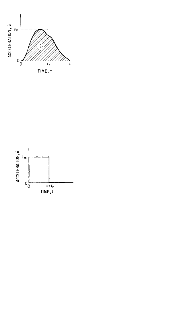
where the value of the integral corre-
sponds to the shaded area of the figure.
The equivalent rectangular pulse is charac-
terized by (a) the same maximum acceler-
ation ü
m
and (b) the same velocity change
˙
u
c
. In Fig. 31.16, the horizontal and vertical
dashed lines outline the equivalent rect-
angular pulse corresponding to the
shaded pulse. From condition (b) above
and Eq. (31.27), the effective duration τ
r
of
the equivalent rectangular pulse is
τ
r
=
τ
0
ü dt (31.28)
where τ
r
may be interpreted physically as the average width of the shaded pulse.
RESPONSE TO A RECTANGULAR PULSE
The rectangular pulse shown in Fig. 31.17 has a maximum acceleration ü
m
and dura-
tion τ; the velocity change is
˙
u
c
= ü
m
τ. The response of an undamped, linear, single
degree-of-freedom system (see Fig.
31.6) to this pulse is found from the dif-
ferential equation obtained by substitut-
ing in Eq. (31.8) F
s
(δ) = kδ from Eq.
(31.15) and ω
n
2
= k/m from Eq. (31.16):
¨
δ+ω
n
2
δ=−ü
m
[0 ≤ t ≤τ] (31.29)
¨
δ+ω
n
2
δ=0[t >τ] (31.30)
Using the initial conditions
˙
δ=0, δ=0
when t = 0, the solution of Eq. (31.29) is
δ= (cos ω
n
t − 1) [0 ≤ t ≤τ] (31.31)
For the solution of Eq. (31.30), it is necessary to find as initial conditions the values
of
˙
δ and δ given by Eq. (31.31) for t =τ. Using these values the solution of Eq.
(31.30) is
δ= [(cos ω
n
τ−1) cos ω
n
(t −τ) − sin ω
n
τ sin ω
n
(t −τ)] [t >τ] (31.32)
The motion defined by Eqs. (31.31) and (31.32) is shown graphically in Fig. 31.18 for
τ=π/2ω
n
, π/ω
n
, and 3π/2ω
n
.
In the isolation of shock, the extreme absolute acceleration
¨
x
m
of the mass is
important. Since
¨
x
m
=ω
n
2
δ
m
[Eq. (31.17)],
¨
x
m
is found directly from the extreme
value of δ. As indicated by Fig. 31.18, for values of τ greater than π/ω
n
, the extreme
(absolute) value of δ encountered at t =π/ω
n
is never exceeded. For values of τ
less than π/ω
n
, the extreme value occurs after the pulse has ended (t >τ) and is
ü
m
ω
n
2
ü
m
ω
n
2
1
ü
m
THEORY OF SHOCK ISOLATION 31.17
FIGURE 31.16 Typical acceleration pulse with
maximum acceleration ü
m
and duration τ.
FIGURE 31.17 Rectangular acceleration pulse.
8434_Harris_31_b.qxd 09/20/2001 12:33 PM Page 31.17
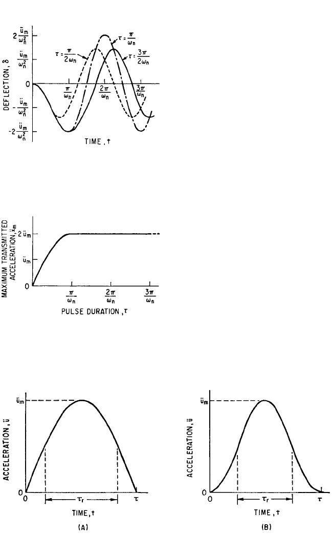
the amplitude of the motion repre-
sented by Eq. (31.32). This amplitude
may be written
δ
m
= 2 sin (31.33)
The extreme absolute values of the
acceleration
¨
x
m
are plotted as a function
of τ in Fig. 31.19. Note that the extreme
value of acceleration is twice that of the
acceleration of the rectangular pulse.
HALF-SINE PULSE
Consider the “half-sine” acceleration
pulse (Fig. 31.20A) of amplitude ü
m
and
duration τ:
ü = ü
m
sin [0 ≤ t ≤τ]
ü = 0[t >τ]
(31.34)
From Eq. (31.28), the effective duration is
τ
r
=τ (31.35)
The response of a single degree-of-
freedom system to the half-sine pulse
of acceleration, corresponding to Eqs.
(31.31) and (31.32) for the rectangular
pulse, is defined by Eq. (8.32).
2
π
πt
τ
ω
n
τ
2
ü
m
ω
n
2
31.18 CHAPTER THIRTY-ONE
FIGURE 31.18 Response curves for an
undamped linear system subjected to rect-
angular acceleration pulses of height ü
m
and var-
ious durations τ.
FIGURE 31.19 Maximum acceleration spec-
trum for a linear system of angular natural fre-
quency ω
n
. Support motion is a rectangular
acceleration pulse of height ü
m
.
FIGURE 31.20 Half-sine acceleration pulse (A) and versed sine acceleration pulse (B).
8434_Harris_31_b.qxd 09/20/2001 12:33 PM Page 31.18
VERSED SINE PULSE
The versed sine pulse (Fig. 31.20B) is described by
ü =
1 − cos
= ü
m
sin
2
[0 ≤ t ≤τ]
ü = 0[t >τ]
(31.36)
The effective duration τ
r
given by Eq. (31.28) is
τ
r
= (
1
⁄2)τ (31.37)
The response of a single degree-of-freedom system to a versed sine pulse is defined
by Eq. (8.33). The responses to a number of other types of pulse and step excitation
also are defined in Chap. 8.
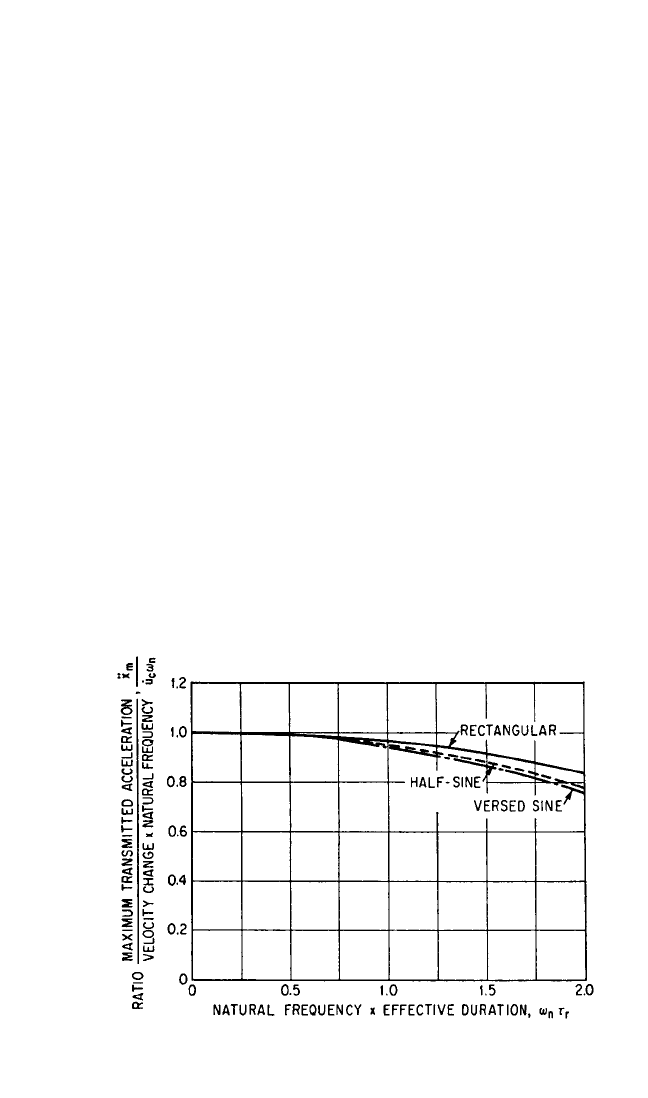
COMPARISON OF MAXIMUM ACCELERATIONS
Velocity Step Approximation. A comparison of values of
¨
x
m
resulting from var-
ious acceleration pulses with that resulting from a velocity step is shown in Fig. 31.21.
The maximum acceleration induced by a velocity step is ω
n
˙
u
m
[see Eq. (31.19)]. The
abscissa ω
n
τ
r
is a dimensionless measure of pulse duration. The effect of pulse shape
is imperceptible for values of ω
n
τ
r
< 0.6. For pulses of duration ω
n
τ
r
< 1.0, the effect
of pulse shape is small and the maximum possible error resulting from use of the
velocity step approximation is of the order of 5 percent.
πt
τ
2πt
τ
ü
m
2
THEORY OF SHOCK ISOLATION 31.19
FIGURE 31.21 Dimensionless representation of maximum transmitted
acceleration
¨
x
m
for the undamped linear system of Fig. 31.6.
8434_Harris_31_b.qxd 09/20/2001 12:33 PM Page 31.19
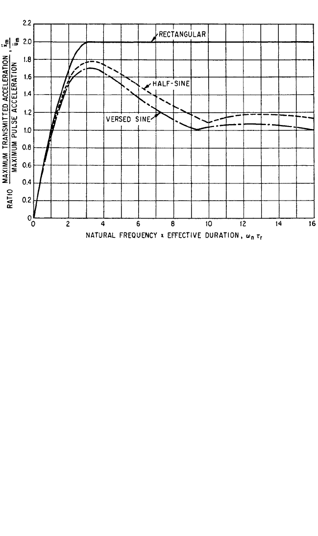
FIGURE 31.22 Shock transmissibility for the undamped linear system of Fig. 31.6 as a function of
angular natural frequency ω
n
and effective pulse duration τ
r
.
Effects of Pulse Shape. The effects of pulse shape upon the maximum response
acceleration
¨
x
m
for values of ω
n
τ
r
> 1.0 are shown in Fig. 31.22. The ordinate
¨
x
m
/ü
m
is
the ratio of maximum acceleration induced in the responding system to maximum
acceleration of the pulse. All three pulses produce the highest value of response
acceleration when ω
n
τ
r
π. Physically, this corresponds to an effective duration τ
r
of
one-half of the natural period of the spring-mass system. For longer pulse durations
the curves for half-sine and versed sine pulses are similar. For pulse durations
beyond the range of Fig. 31.22 (ω
n
τ
r
> 16), the half-sine and versed sine curves
approach the limiting ordinate
¨
x
m
/ü
m
= 1. This corresponds physically to approximat-
ing a static loading of the spring-mass system. A limiting acceleration ratio
¨
x
m
/ü
m
= 2
is encountered for all rectangular pulses of duration greater than the half-period of
the spring-mass system. A more extensive study of responses to a variety of pulse
shapes is included in Chap. 8.
SHOCK RESPONSE SPECTRUM
The abscissa ω
n
τ
r
in Fig. 31.22 may be treated as a measure of pulse duration (pro-
portional to τ
r
) for a given spring-mass system with ω
n
fixed. Alternatively, the pulse
duration may be considered fixed; then the curves show the effect of varying the nat-
ural frequency ω
n
of the spring-mass system. Each of the curves of Fig. 31.22 shows
the maximum acceleration induced by a given acceleration pulse upon spring-mass
systems of various natural frequencies ω
n
; thus, Fig. 31.22 may be used to determine
the required natural frequency of the isolator if
¨
x
m
and ü
m
are known, and the pulse
shape is defined.
31.20 CHAPTER THIRTY-ONE
8434_Harris_31_b.qxd 09/20/2001 12:33 PM Page 31.20
THEORY OF SHOCK ISOLATION 31.21
Each curve shown in Fig. 31.22 may be interpreted as a description of a pulse, in
terms of the response induced in a system subjected to the pulse. The curve of maxi-
mum response as a function of the natural frequency of the responding system is
called a shock response spectrum or response spectrum. This concept is discussed
more fully in Chap. 23.A pulse is a particular form of a shock motion; thus, each shock
motion has a characteristic shock response spectrum. A shock motion has a charac-
teristic effective value of time duration τ
r
which need not be defined specifically;
instead, the spectra are made to apply explicitly to a given shock motion by using the
natural frequency ω
n
as a dimensional parameter on the abscissa. By taking the isola-
tor-and-equipment assembly to be the responding system, the natural frequency of
the isolator may be chosen to meet any specified maximum acceleration
¨
x
m
of the
equipment supported by isolators. Spectra of maximum isolator deflection δ
m
also
may be drawn, and are useful in predicting the maximum isolator deflection when the
natural frequency of the isolator is known.
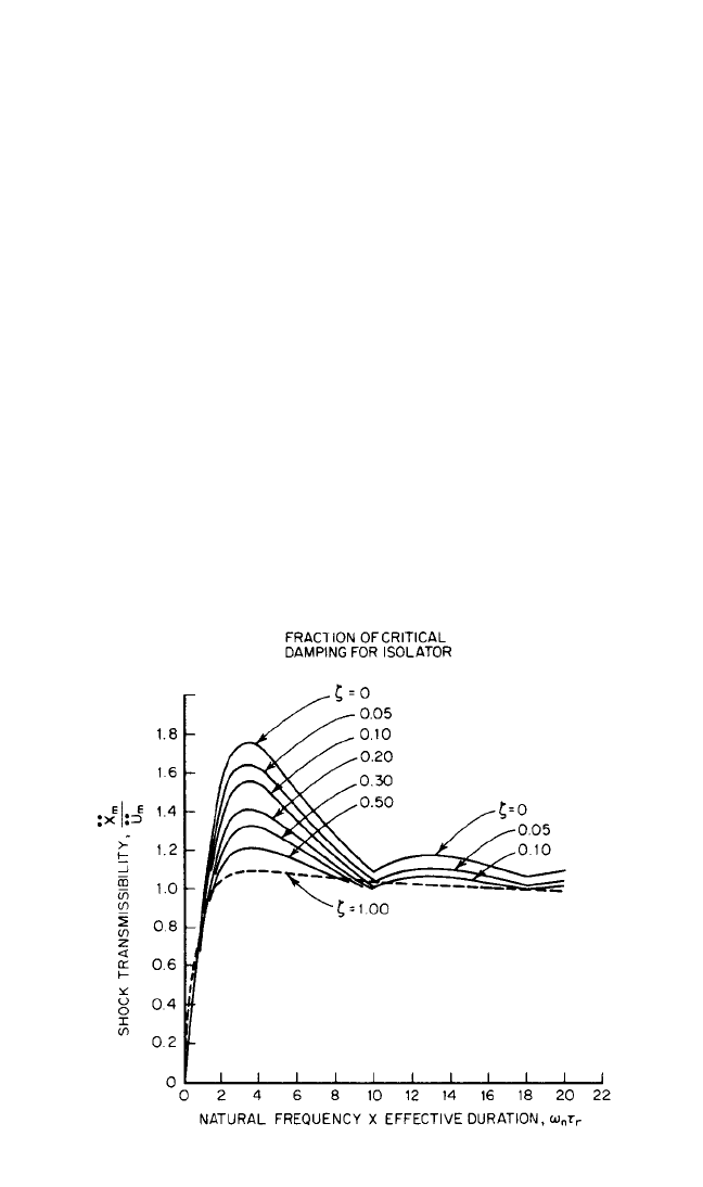
When damping is added to the isolator, the analysis of the response becomes
much more complex. In general, it is possible to determine the maximum value of
the response acceleration
¨
x
m
only by calculating the time-history of response accel-
eration over the entire time interval suspected of including the maximum response.
A digital computer has been used to find shock response spectra for “half-sine”
acceleration pulses with various fractions of critical damping in the responding sys-
tem, as shown in Fig. 31.23. Similar spectra could be obtained to indicate maximum
values of isolator deflection. In selecting a shock isolator for a specified application,
it may be necessary to use both maximum acceleration and maximum deflection
spectra. This is illustrated in the following example.
FIGURE 31.23 Shock transmissibility for the system of Fig. 31.2A with
linear spring and viscous damping.
8434_Harris_31_b.qxd 09/20/2001 12:33 PM Page 31.21
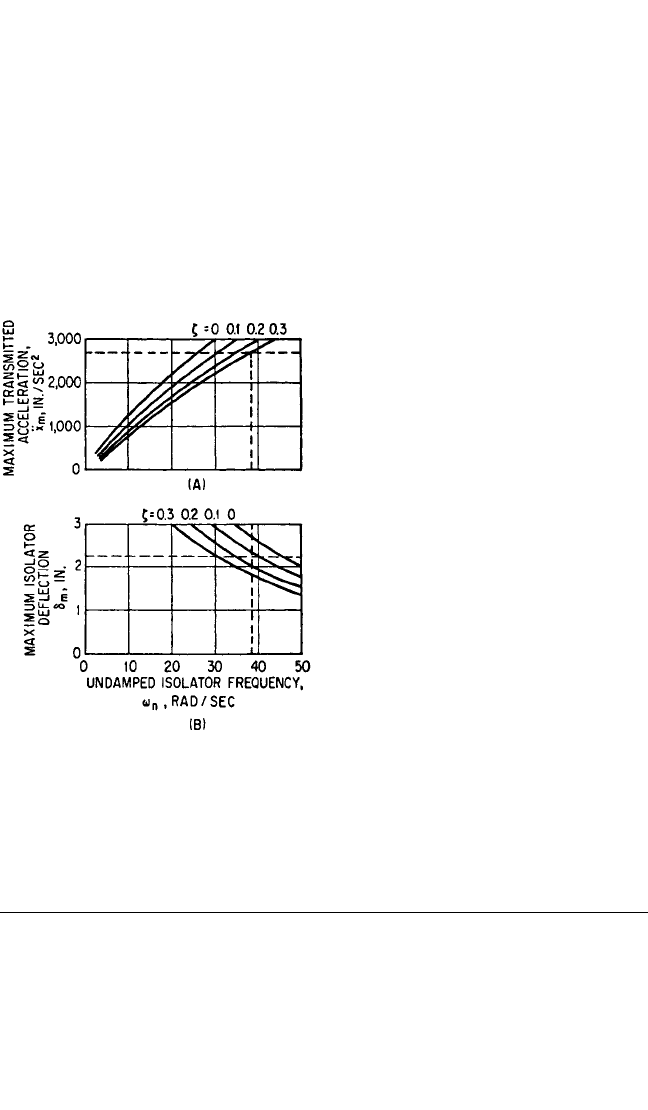
Example 31.2. A piece of equipment weighing 230 lb is to be isolated from the
effects of a vertical shock motion defined by the spectra of acceleration and deflec-
tion shown in Fig. 31.24. It is required that the maximum induced acceleration not
exceed 7g (2700 in./sec
2
). Clearances available limit the isolator deflection to 2.25 in.
The curves in Fig. 31.24A represent maximum response acceleration
¨
x
m
as a function
of the angular natural frequency ω
n
of the equipment supported on the shock isola-
tors. The isolator springs are assumed linear and viscously damped, and separate
curves are shown for values of the damping ratio ζ=0, 0.1, 0.2, and 0.3. The curves in
Fig. 31.24B represent the maximum isolator deflection δ
m
as a function of ω
n
for the
same values of ζ.
Consider first the requirement that
¨
x
m
< 2700 in./sec
2
. In Fig. 31.24A, the hori-
zontal dashed line indicates this limiting acceleration. If the damping ratio ζ=0.3,
then the angular natural frequency ω
n
may not exceed 38.5 rad/sec on the crite-
rion of maximum acceleration. The
dashed horizontal line of Fig. 31.24B rep-
resents the deflection limit δ
m
= 2.25 in.
For ζ=0.3, the minimum natural fre-
quency is 30 rad/sec on the criterion of
deflection. Considering both accelera-
tion and deflection criteria, the angular
natural frequency ω
n
must lie between 30
rad/sec and 38.5 rad/sec. The spectra
indicate that both criteria may be just
met with ζ=0.2 if ω
n
is 35 rad/sec.
Smaller values of damping do not permit
the satisfaction of both requirements.
Conservatively, a suitable choice of
parameters is ζ=0.3, ω
n
= 35 rad/sec.
This limits
¨
x
m
to 2500 in./sec
2
and δ
m
to
2.0 in. The spring stiffness k is
k =ω
n
2
m = (35)
2
×=730 lb/in.
If the equipment is to be supported by
four like isolators, then the required stiff-
ness of each isolator is k/4 = 182.5 lb/in.
RESPONSE OF EQUIPMENT WITH A FLEXIBLE
COMPONENT
IMPACT WITH REBOUND
Consider the system of Fig. 31.4. The block of mass m
1
represents the equipment and
m
2
with its associated spring-dashpot unit represents a critical component of the equip-
ment.The left spring-dashpot unit represents the shock isolator. It is assumed here that
m
1
>> m
2
so that the motion of m
1
is not sensibly affected by m
2
; larger values of m
2
are
considered in a later section. Consider the entire system to be moving to the left at uni-
form velocity when the left-hand end of the isolator strikes a fixed support (not
230
386
FIGURE 31.24 Shock response spectra: (A)
maximum acceleration and (B) maximum isola-
tor deflection for Example 31.2.
31.22 CHAPTER THIRTY-ONE
8434_Harris_31_b.qxd 09/20/2001 12:33 PM Page 31.22

THEORY OF SHOCK ISOLATION 31.23
shown).The isolator will be compressed until the equipment is brought to rest. Follow-
ing this the compressive force in the isolator will continue to accelerate the equipment
toward the right until the isolator loses contact with the support and the rebound is
complete. This type of shock is called impact with rebound. Practical examples include
the shock experienced by a single railroad car striking a bumper at the end of a siding
and that experienced by packaged equipment, shock-mounted inside a container of
small mass, when the container is dropped upon a hard surface and then rebounds.
The procedure for finding the maximum acceleration
¨
x
2m
of the component,
assuming the component stiffness to be linear and neglecting component damping, is:
1. Using the known striking velocity determine, from velocity step results (Figs.
31.9, 31.10, 31.12 to 31.15), the maximum deflection δ
1m
of the isolator and the
maximum acceleration
¨
x
1m
of the equipment.
2. From Eq. (31.28), find the effective duration τ
r
for the acceleration time-history
¨
x
1
(t) of the equipment.
3. From the shock spectra corresponding to the acceleration pulse
¨
x
1
(t), find the
maximum acceleration
¨
x
2m
of the component.
Details of the procedure using the isolators of Example 31.1 are considered in
Example 31.3.
Example 31.3. Let the equipment of Example 31.1 weighing 40 lb have a flexi-
ble component weighing 0.2 lb. By vibration testing, this component is found to have
an angular natural frequency ω
n
= 260 rad/sec and to possess negligible damping. For
the isolators of Example 31.1, it is desired to determine the maximum acceleration
¨
x
2m
experienced by the mass m
2
of the component if the equipment, traveling at a
velocity of 70 in./sec, is arrested by the free end of the isolator striking a fixed sup-
port. The four cases are considered separately. It is assumed that the component has
a negligible effect on the motion of the equipment because m
2
<< m
1
.
Linear Spring. From the results of Example 31.1, it is known that ω
n
= 108 rad/sec
and that the maximum acceleration of the equipment as found from Eq. (31.19) is
¨
x
1m
= 7580 in./sec
2
= 19.6g
This acceleration occurs at the instant when the isolator deflection has the extreme
value δ
1m
= 0.65 in. [If the equipment (Fig. 31.4) is moving toward the left when the
isolator contacts the support, the extreme value of δ
1m
is negative. It suffices to deal
here with absolute values.] Subsequently the isolator spring continues to accelerate
the equipment until the isolator force is zero and the rebound is complete. Since
there is no damping, the rebound velocity equals the striking velocity (with opposite
sign). The velocity change
˙
x
1c
is twice the striking velocity and the effective duration
τ
r
[Eq. (31.28)] is
τ
r
== =0.0185 sec
The acceleration time-history of the equipment is a half-sine pulse as represented in
Fig. 31.20 (the ordinate is
¨
x
1
instead of ü).
Since the equipment is the “support” for the component, the response of the lat-
ter may be found from results developed for the response of a rigid body whose sup-
port experiences a half-sine pulse of acceleration. The half-sine curve of Fig. 31.22
gives the desired information if the following interpretations are made: For
¨
x
m
/ü
m
read
¨
x
2m
/
¨
x
1m
; for ω
n
τ
r
read ω
n2
τ
r
. Now ω
n2
τ
r
= 260 × 0.0185 = 4.80. From Fig. 31.22,
¨
x
2m
/
¨
x
1m
= 1.66, and
¨
x
2m
= 1.66 × 7580 = 12,600 in./sec
2
= 32.6g.
2 × 70
7580
˙
x
1c
¨
x
1m
8434_Harris_31_b.qxd 09/20/2001 12:33 PM Page 31.23
Hardening Spring. From Example 31.1, the maximum equipment acceleration
is
¨
x
1m
= 21g = 8100 in./sec
2
. Since the velocity change
˙
x
1c
is twice the striking velocity,
the effective duration τ
r
[Eq. (31.28)] is
τ
r
== =0.0173 sec
With a hardening isolator spring, the shape of the acceleration pulse
¨
x
1
(t) experienced
by the equipment varies considerably as the maximum deflection δ
1m
approaches the
upper limit d. Up to δ
1m
/d = 0.5, the shape is closely approximated by a half-sine pulse.
For δ
1m
/d = 0.8, a symmetric triangular pulse is a good approximation. For higher val-
ues of δ
1m
/d, the pulse is very sharply peaked.The maximum response curve for a half-
sine pulse is given in Fig. 31.22. The corresponding curve for a symmetric triangular
pulse (Fig. 8.18b) is similar to that for the versed sine pulse, though lying generally
below the latter. Inasmuch as the curve for the versed sine pulse is below that for the
half-sine pulse, it is conservative to use the half-sine pulse for all values of δ
1m
/d.
Accordingly, ω
n2
τ
r
= 260 × 0.0173 = 4.50. From the half-sine curve of Fig. 31.22,
¨
x
2m
/
¨
x
1m
= 1.69, and
¨
x
2m
= 1.69 × 8100 = 13,700 in./sec
2
= 36.4g.
Softening Spring. From Example 31.1, the maximum equipment acceleration
¨
x
1m
is
¨
x
1m
= 20g = 7720 in./sec
2
The effective duration τ
r
[Eq. (31.28)] is
τ
r
== =0.0181 sec
The shape of the acceleration pulse
¨
x
1
(t) for the equipment varies markedly as the
departure from linearity increases (increasing values of δ
1m
/d
1
). The pulse shape is
found by first performing the integration of Eq. (31.9) with F
s
(δ) as given by Eq.
(31.23). The result supplies the integrand required for Eq. (31.13). A numerical inte-
gration of the latter equation shows that
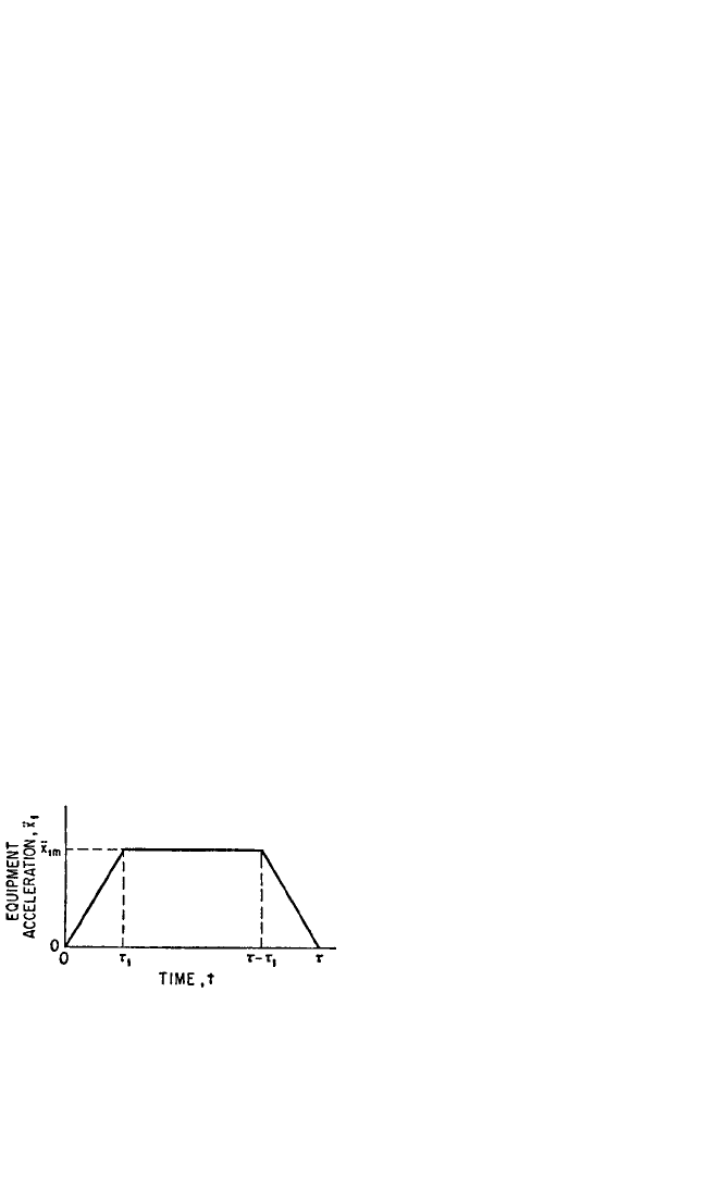
the pulse shape undergoes a rapid transi-
tion from the half-sine pulse at very
small values of δ
1m
/d
1
to shapes that are
closely approximated by the trapezoidal
pulse of Fig. 31.25. Note that the pulse of
Fig. 31.25 requires three parameters to
fix it completely: the maximum accelera-
tion
¨
x
1m
; the effective duration τ
r
; and the
ratio τ
r
/τ, where τ is the actual duration
and τ
r
=τ−τ
1
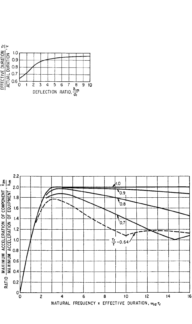
. From results of the numer-
ical integrations of Eq. (31.13), the curve
of Fig. 31.26 is constructed to show τ
r
/τ as
a function of the deflection ratio δ
1m
/d
1
.
To find the maximum acceleration
¨
x
2m
of the component, the maximum
response curves (shock spectra) of Fig. 31.27 are used. These curves are constructed
for symmetric trapezoidal pulses (Fig. 31.25). The top curve (τ
r
/τ=1.0) corresponds
to the limiting (rectangular) form. The dashed curve (τ
r
/τ=0.64) represents
response to a half-sine pulse.
2 × 70
7720
˙
x
1c
¨
x
1m
2 × 70
8100
˙
x
1c
¨
x
1m
31.24 CHAPTER THIRTY-ONE
FIGURE 31.25 Symmetric trapezoidal accel-
eration pulse.
8434_Harris_31_b.qxd 09/20/2001 12:33 PM Page 31.24
The value of δ
1m
/d
1
corresponding to the maximum acceleration
¨
x
1m
of the
equipment is (from Example 31.1) δ
1m
/d
1
= 3. From Fig. 31.26: τ
r
/τ=0.88. Now
ω
n
τ
r
= 260 × 0.0181 = 4.7. Using Fig. 31.27, linear interpolation between the curves for
τ
r
/τ=0.8 and τ
r
/τ=0.9 gives
¨
x
2m
/
¨
x
1m
=
1.98 and
¨
x
2m
= 1.98 × 7720 = 15,300
in./sec
2
= 39.6g.
Linear Spring and Viscous Damp-
ing. The presence of damping in the
isolator adds several complications: (1)
the rebound velocity is no longer equal
to the striking velocity; (2) the accelera-
tion pulse of the equipment is not sym-
metrical and returns to zero before the
isolator deformation δ
1m
returns to zero;
and (3) the pulse shape varies greatly
with damping ratio ζ
1
. Shock response
spectra for acceleration pulse shapes
corresponding to damping ratios of par-
ticular interest (0.10 <ζ
1
< 0.40) are not
available. However, for single accelera-
tion pulses which do not change sign, it is conservative to assume that the maximum
acceleration
¨
x
2m
of the component is twice the maximum acceleration
¨
x
1m
of the
equipment. Using the results of Example 31.1, the maximum acceleration of the
component is
¨
x
2m
= 2
¨
x
1m
= 2 × 5450 = 10,900 in./sec
2
= 28.2g.
THEORY OF SHOCK ISOLATION 31.25
FIGURE 31.26 Dimensionless representation
of effective duration τ
r
of acceleration pulse
experienced by equipment during impact with
rebound.
FIGURE 31.27 Shock response spectra for component having undamped linear elasticity with
angular natural frequency ω
n2
.
8434_Harris_31_b.qxd 09/20/2001 12:33 PM Page 31.25