Harris C.M., Piersol A.G. Harris Shock and vibration handbook
Подождите немного. Документ загружается.

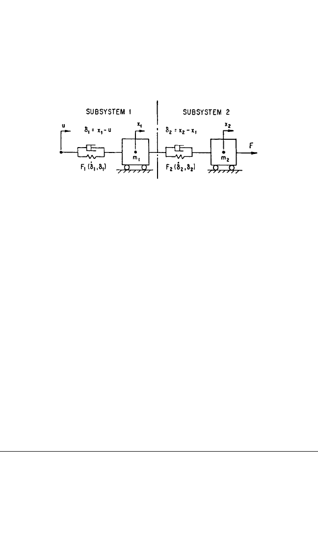
system is represented by two separate single degree-of-freedom systems, as shown in
Figs. 31.2B and 31.3B, the time-history of F(
˙
δ,δ) is also required. Figure 31.4 may be
considered a generalized form of the applicable system. In Class I, F = 0, F
1
(
˙
δ
1
,δ
1
)
represents the properties of the isolator, and m
2
,F
2
(
˙
δ
2
,δ
2
) represents the component
to be protected. In Class II, u = 0, F
2
(
˙
δ
2
,δ
2
) represents the properties of the isolator,
and m
1
,F
1
(
˙
δ
1
,δ
1
) represents the supporting structure.
The system of Fig. 31.4, with the spring-dashpot units nonlinear, requires the use
of a digital computer to investigate performance characteristics. Analytical methods
are feasible if the system is linearized by assuming that each spring-dashpot unit has
a force characteristic in the form
F(
˙
δ,δ) = c
˙
δ+kδ (31.7)
where c = damping coefficient, lb-sec/in., and k = spring stiffness, lb/in. Even with this
simplification, the number of parameters (m
1
,c
1
,k
1
,m
2
,c
2
,k
2
) is so great that it is nec-
essary to confine the analysis to a particular system. If the damping may be neg-
lected [let c = 0 in Eq. (31.7)], then it is feasible to obtain equations in a form suitable
for routine use. Use of this idealization is described in the section on Response of
Equipment with a Flexible Component.
A different form of idealization is indicated when the “equipment” is flexible;
e.g., a large, relatively flexible aircraft subjected to landing shock. Then it is impor-
tant to represent the aircraft as a system with several degrees-of-freedom. To find
resulting stresses, it is necessary to superimpose the responses in the various modes
of motion that are excited.
RESPONSE OF A RIGID BODY SYSTEM
TO A VELOCITY STEP
PHYSICAL BASIS FOR VELOCITY STEP
The idealization of a shock motion as a simple change in velocity (velocity step) may
form an adequate basis for designing a shock isolator and for evaluating its effec-
tiveness. Consider the two types of acceleration ü vs. time t curves illustrated in Fig.
31.5A. The solid line represents a rectangular pulse of acceleration and the dashed
line represents a half-sine pulse of acceleration. Each pulse has a duration τ. In Fig.
31.6 CHAPTER THIRTY-ONE
FIGURE 31.4 General two degree-of-freedom system.
8434_Harris_31_b.qxd 09/20/2001 12:33 PM Page 31.6
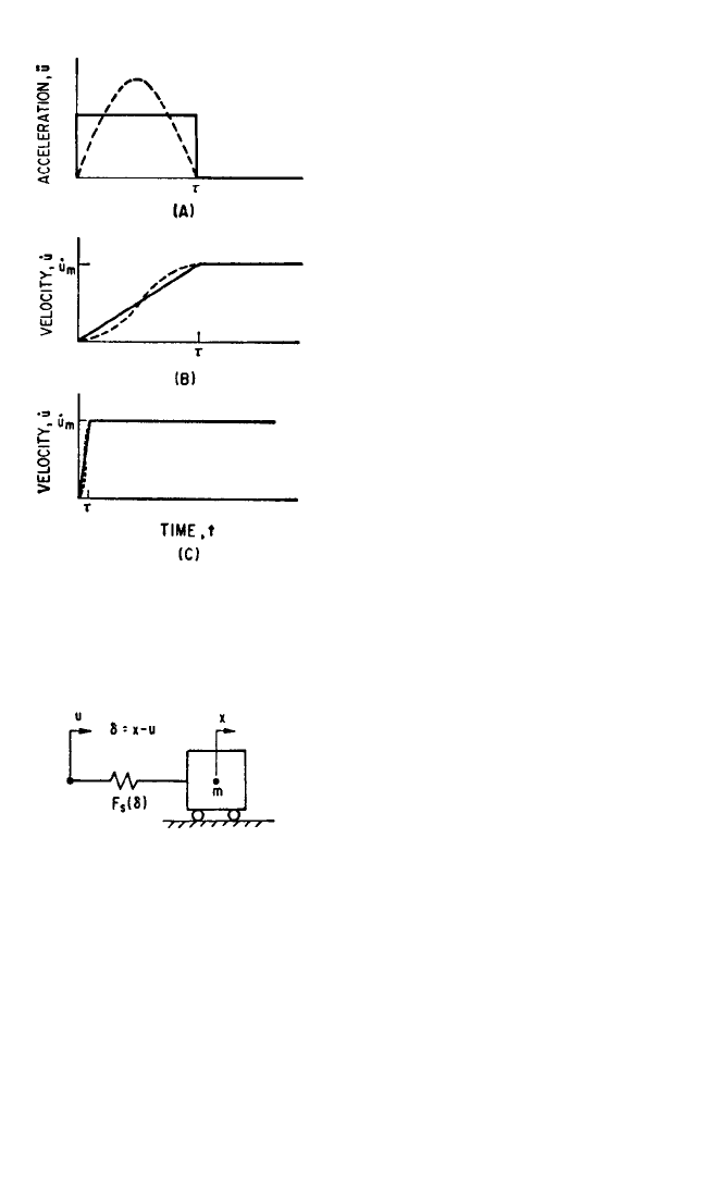
31.5B, the corresponding velocity-time
curves are shown. Each of these curves
is defined completely by specifying the
type of acceleration pulse (rectangular
or half-sine), the duration τ, and the
velocity change
˙
u
m
. The curves of Fig.
31.5B are repeated in Fig. 31.5C with the
time scale shrunk to one-tenth. If τ is
sufficiently short, the only significant
remaining characteristic of the velocity
step is the velocity change
˙
u
m
. The ideal-
ized velocity step, then, is taken to be a
discontinuous change of
˙
u from zero to
˙
u
m
. A shock isolator characteristically
has a low natural frequency (long
period), and this idealization leads to
good results even when the pulse dura-
tion τ is significantly long.
GENERAL FORM OF ISOLATOR
CHARACTERISTICS
The differential equation of motion
for the undamped, single degree-of-
freedom system shown in Fig. 31.6 is
m
¨
δ+F
s
(δ) =−mü (31.8)
where m represents the mass of the
equipment considered as a rigid body, u
represents the motion of the support
which characterizes the condition of
shock, and F
s
(δ) is the force developed
by the isolator at an extension δ (posi-
tive when tensile). Equation (31.8) dif-
fers from Eq. (31.5) in that F
s
(δ), which
does not depend upon
˙
δ, replaces F(
˙
δ,δ)
because the isolator is undamped. The
effect of a velocity step of magnitude
˙
u
m
at t = 0 is considered by choosing the ini-
tial conditions: At t = 0, δ=0 and
˙
δ=
˙
u
m
.
These conditions correspond to a negative velocity step.This choice is made to avoid
dealing with negative values of δ and
˙
δ. If F
s
(δ) is not an odd function of δ, a positive
velocity step requires a separate analysis.
A first integration of Eq. (31.8) yields
˙
δ
2
=
˙
u
m
2
−
δ
0
F
s
(δ)dδ (31.9)
At the extreme value of isolator deflection, δ=δ
m
and the velocity
˙
δ of deflection is
zero. Then from Eq. (31.9),
2
m
THEORY OF SHOCK ISOLATION 31.7
FIGURE 31.5 Acceleration-time curves (A)
and velocity-time curves (B) and (C) for rect-
angular acceleration pulse (solid curves) and
half-sine acceleration pulse (dashed curves).
FIGURE 31.6 Idealized system showing use of
undamped isolator to protect equipment from
effects of support motion u.
8434_Harris_31_b.qxd 09/20/2001 12:33 PM Page 31.7
δ
m
0
F
s
(δ)dδ=
1
⁄2m
˙
u
m
2
(31.10)
The right side of Eq. (31.10) represents the initial kinetic energy of the equipment
relative to the support, and the integral on the left side represents the work done on
the isolator. The latter quantity is equal to the elastic potential energy stored in the
isolator, since there is no damping.
For the special case of a rigid body mounted on an undamped isolator, Eq. (31.10)
suffices to determine all important results. In particular, the quantities of engineer-
ing significance are:
1. The maximum deflection of the isolator δ
m
2. The maximum isolator force, F
m
= F
s
(δ
m
) = m
¨
x
m
3. The corresponding velocity change
˙
u
m
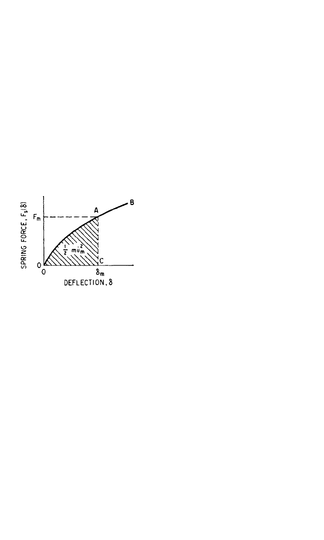
The interrelations of these three quanti-
ties are shown graphically in Fig. 31.7.
The curve OAB represents the spring
force F
s
(δ) as a function of deflection δ.
If point A corresponds to the extreme
excursion, then its abscissa represents
the maximum deflection δ
m
. The shaded
area OAC is proportional to the poten-
tial energy stored by the isolator;
according to Eq. (31.10), this is equal to
the initial kinetic energy m
˙
u
m
2
/2. The
maximum ordinate (at A) represents the
maximum spring force F
m
. [It is possible
to have a spring force F
s
(δ) which attains
a maximum value at δ=δ
f
<δ
m
. Then
F
m
= F
s
(δ
f
).]
The design requirements for the isolator usually include as a specification one or
more of the following quantities:
1. Maximum allowable deflection δ
a
2. Maximum allowable transmitted force F
a
3. Maximum expected velocity step
˙
u
a
It is important to observe that the limits 1 and 2 establish an upper limit F
a
δ
a
on the
work done on the mass. It follows that
˙
u
a
must satisfy the relation
F
a
δ
a
≥ m
˙
u
a
2
/2
or the specifications are impossible to meet. The specifications may be expressed
mathematically as follows:
δ
m
≤δ
a
F
m
≤ F
a
˙
u
m
≥
˙
u
a
(31.11)
In many instances it is advantageous to eliminate explicit reference to the mass
m. Then the allowable absolute acceleration
¨
x
a
of the mass is specified instead of the
31.8 CHAPTER THIRTY-ONE
FIGURE 31.7 Typical force-deflection curve
for undamped isolator.
8434_Harris_31_b.qxd 09/20/2001 12:33 PM Page 31.8

allowable force F
a
where F
a
= m
¨
x
a
. With this substitution the second of Eqs. (31.11)
is replaced by
¨
x
m
≤
¨
x
a
(31.12)
The acceleration
¨
x is determined as a function of time by using
˙
δ from Eq. (31.9) and
finding the time t corresponding to a given value of δ:
t =
δ
0
(31.13)
From Eq. (31.13) and the relation
¨
x = F
s
(δ)/m, the acceleration time-history is
found.
The integrations required by Eqs. (31.9) and (31.13) sometimes are difficult to
perform, and it is necessary to use numerical methods. Then a difficulty arises with
the integral in Eq. (31.13). As δ approaches the extreme value δ
m
, the velocity
˙
δ in
the denominator of the integrand approaches zero. The difficulty is circumvented by
first using Eq. (31.13) to integrate up to some intermediate displacement δ
b
less than
δ
m
; then the alternative form, Eq. (31.14), may be used in the region of δ=δ
m
:
t = t
b
+
˙
δ
˙
δ
b
(31.14)
where t
b
is the time at which δ=δ
b
, as determined from Eq. (31.13).
In the next three sections three different kinds of spring force-deflection charac-
teristics F
s
(δ) are considered. Equation (31.10) is applied to find the relation
between
˙
u
m
and δ
m
. Curves relating
˙
u
m
, δ
m
, and
¨
x
m
in a form useful for design or analy-
sis are presented.
EXAMPLES OF PARTICULAR ISOLATOR CHARACTERISTICS
Linear Spring. The force-deflection characteristic of a linear spring is
F
s
(δ) = kδ (31.15)
where k = spring stiffness, lb/in. Using the notation
ω
n
=
rad/sec (31.16)
the maximum acceleration is
¨
x
m
=ω
n
2
δ
m
(31.17)
From Eqs. (31.10) and (31.16), the relation between velocity change
˙
u
m
and maxi-
mum deflection δ
m
is
˙
u
m
=ω
n
δ
m
(31.18)
Combining Eqs. (31.18) and (31.17),
¨
x
m
=ω
n
˙
u
m
(31.19)
k
m
d
˙
δ
¨
δ
dδ
˙
δ
THEORY OF SHOCK ISOLATION 31.9
8434_Harris_31_b.qxd 09/20/2001 12:33 PM Page 31.9
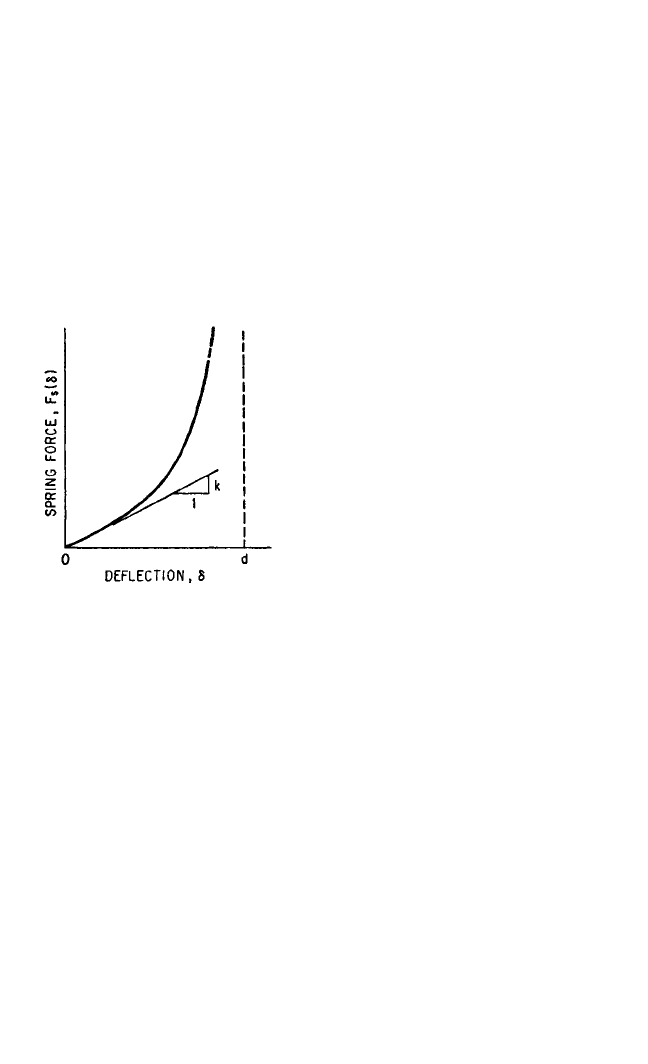
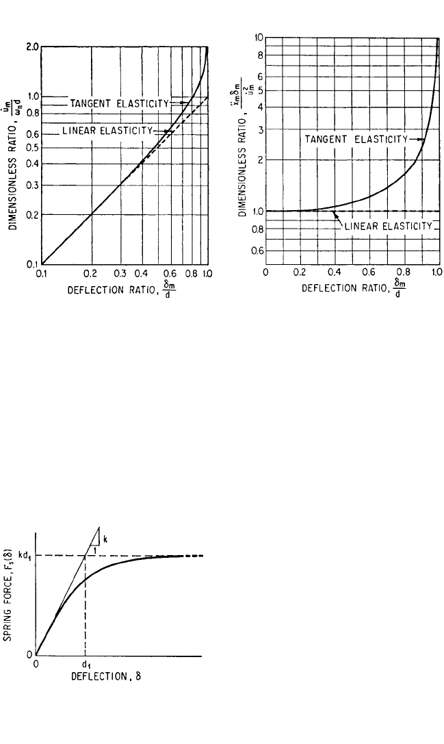
Hardening Spring (Tangent Elasticity). The isolator spring may be nonlinear
with a “hardening” characteristic; i.e., the slope of the curve representing spring
force vs. deflection increases with increasing deflection. Rubber in compression has
this behavior.A representative curve having this characteristic is defined by
F
s
(δ) = tan (31.20)
where the constant k is the initial slope of the curve (lb/in.) and a vertical asymptote
is defined by δ=d (in.). Such a curve is shown graphically in Fig. 31.8. Using the
notation of Eq. (31.16) and the relation m
¨
x
m
= F
s
(δ
m
), Eq. (31.20) gives the following
relation between maximum acceleration and maximum deflection:
= tan (31.21)
Note that ω
n
, the angular natural fre-
quency for a linear system, has the same
meaning for small amplitude (small δ
m
)
motions of the nonlinear system. For
large amplitudes the natural frequency
depends on δ
m
. Using Eq. (31.16), substi-
tuting for F
s
(δ) from Eq. (31.20) in Eq.
(31.10), and performing the indicated
integration, the relation between veloc-
ity change and maximum displacement
is
= log
e
sec
(31.22)
A graphical presentation relating the
important variables
˙
u
m
,
¨
x
m
, and δ
m
is con-
venient for design and analysis. Such data are presented compactly as relations
among the dimensionless parameters δ
m
/d,
˙
u
m
/ω
n
d, and
¨
x
m
δ
m
/
˙
u
m
2
.The physical signif-
icance of the ratio
¨
x
m
δ
m
/
˙
u
m
2
is interpreted by multiplying both numerator and
denominator by m. Then the numerator represents the product of the maximum
spring force F
m
(= m
¨
x
m
) and the maximum spring deflection δ
m
. This product is the
maximum energy that could be stored in the spring. The denominator m
˙
u
m
2
is twice
the energy that is stored in the spring. The minimum possible value of the ratio
¨
x
m
δ
m
/
˙
u
m
2
is
1
⁄2. Actual values of the ratio, always greater than
1
⁄2, may be considered to
be a measure of the departure from optimum capability.
In Fig. 31.9 the solid curve represents
˙
u
m
/ω
n
d as a function of δ
m
/d and the dashed
curve shows the corresponding result for a linear spring [see Eq. (31.18)]. In Fig.
31.10 the solid curve shows
¨
x
m
δ
m
/
˙
u
m
2
vs. δ
m
/d for an isolator with tangent elasticity.
The dashed curve in Fig. 31.10 shows
¨
x
m
δ
m
/
˙
u
m
2
for a linear spring [see Eqs. (31.17)
and (31.18)]; the ratio is constant at a value of unity because a linear spring is 50 per-
cent efficient in storage of energy, independent of the deflection.
Softening Spring (Hyperbolic Tangent Elasticity). A nonlinear isolator also
may have a “softening” characteristic; i.e., the slope of the curve representing force
πδ
m
2d
8
π
2
˙
u
m
2
ω
n
2
d
2
πδ
m
2d
2
π
¨
x
m
ω
n
2
d
πδ
2d
2kd
π
31.10 CHAPTER THIRTY-ONE
FIGURE 31.8 Typical force-deflection curve
for hardening spring (tangent elasticity).
8434_Harris_31_b.qxd 09/20/2001 12:33 PM Page 31.10
vs. deflection decreases with increasing deflection. The force-deflection characteris-
tic for a typical “softening” isolator is
F
s
(δ) = kd
1
tanh (31.23)
where k is the initial slope of the curve. Figure 31.11 shows the form of this curve
where the meaning of d
1
is evident from the figure. If F
s
(δ) is replaced by m
¨
x
m
, δ by
δ
m
, and k by mω
n
2
, Eq. (31.23) becomes
= tanh (31.24)
where δ
m
and
¨
x
m
are maximum values of
deflection and acceleration, respec-
tively, and ω
n
may be interpreted as the
angular natural frequency for small val-
ues of δ
m
. To relate
˙
u
m
to δ
m
, substitute
F
s
(δ) from Eq. (31.23) in Eq. (31.10), let
ω
n
2
= k/m, and integrate:
= log
e
cosh
2
(31.25)
A graphical presentation of the rela-
tion between
˙
u
m
/ω
n
d
1
and δ
m
/d
1
is given
δ
m
d
1
˙
u
m
2
ω
n
2
d
1
2
δ
m
d
1
¨
x
m
ω
n
2
d
1
δ
d
1
THEORY OF SHOCK ISOLATION 31.11
FIGURE 31.9 Dimensionless representation
of relation between velocity step
˙
u
m
and maxi-
mum isolator deflection δ
m
for undamped iso-
lators.
FIGURE 31.10 Dimensionless representation
of relation among velocity step
˙
u
m
, maximum
transmitted acceleration
¨
x
m
, and maximum isola-
tor deflection δ
m
for undamped isolators.
FIGURE 31.11 Typical force-deflection curve
for softening spring (hyperbolic tangent elas-
ticity).
8434_Harris_31_b.qxd 09/20/2001 12:33 PM Page 31.11
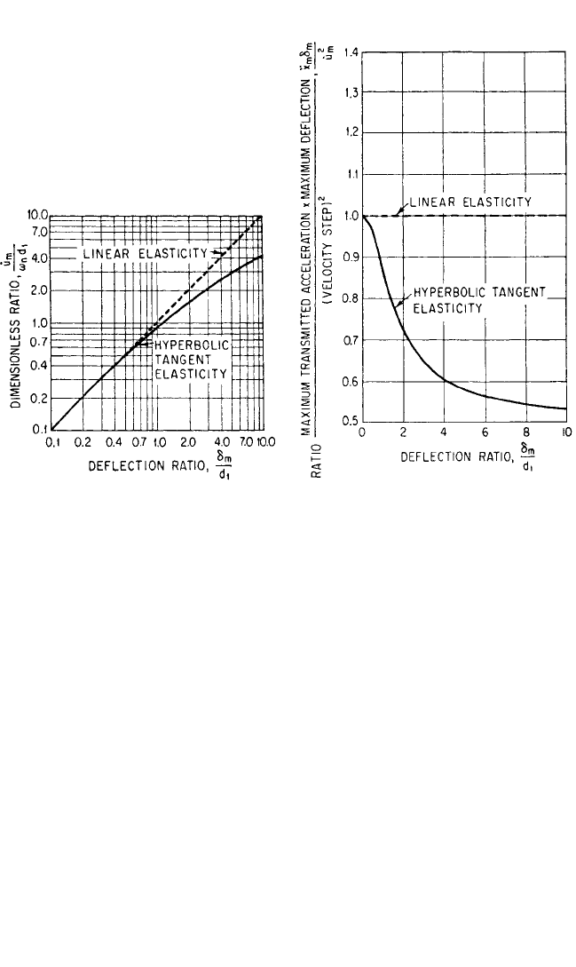
by the solid curve of Fig. 31.12. The dashed curve shows the corresponding relation
for a linear spring. In Fig. 31.13 the solid curve represents
¨
x
m
δ
m
/
˙
u
m
2
as a function of
δ
m
/d
1
. Note that, for large values of δ
m
/d
1
, the ordinate approaches the minimum
value
1
⁄2 attainable with an isolator of optimum energy storage efficiency.The dashed
curve shows the same relation for a linear spring.
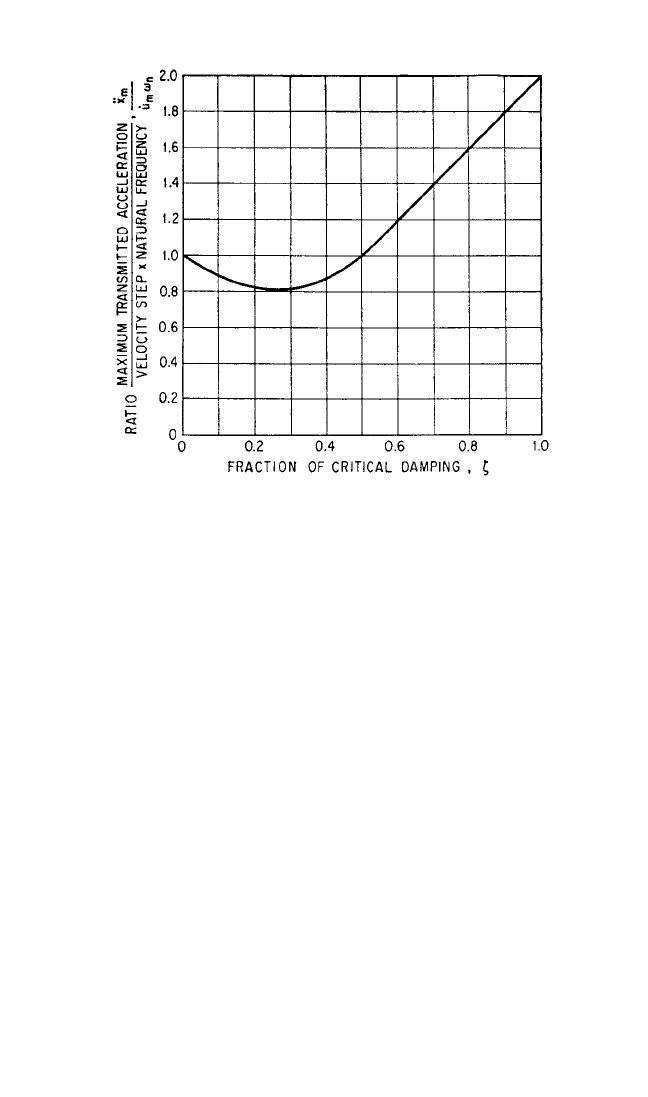
Linear Spring and Viscous Damping. The addition of viscous damping can
almost double the energy absorption capability of a linear shock isolator. Consider
the system of Fig. 31.2A, with both spring and dashpot linear as defined by Eq.
(31.7). Substituting F(
˙
δ,δ) from Eq. (31.7) in Eq. (31.5) gives the equation of motion.
The initial conditions are
˙
δ=
˙
u
m
, δ=0, when t = 0; for t > 0, ü = 0. Letting c
c
= 2mω
n
and ζ=c/c
c
[see Eq. (2.12)], the equation of motion becomes
¨
δ+2ζω
n
˙
δ+ω
n
2
δ=0 (31.26)
Solutions of Eq. (31.26) for maximum deflection δ
m
and maximum acceleration
¨
x
m
as
functions of ζ are shown graphically in Figs. 31.14 and 31.15. In Fig. 31.14, the dimen-
sionless ratio
¨
x
m
/
˙
u
m
ω
n
is plotted as a function of the fraction of critical damping ζ.
Note that the presence of small damping reduces the maximum acceleration. As ζ is
increased beyond 0.25, the maximum acceleration increases again. For ζ>0.50, the
maximum acceleration occurs at t = 0 and exceeds that for no damping; it is
accounted for solely by the damping force c
˙
δ=c
˙
u
m
.
31.12 CHAPTER THIRTY-ONE
FIGURE 31.12 Dimensionless representation
of relation between velocity step
˙
u
m
and maxi-
mum isolator deflection δ
m
for undamped iso-
lators.
FIGURE 31.13 Dimensionless representation
of energy-storage capabilities of undamped iso-
lators.
8434_Harris_31_b.qxd 09/20/2001 12:33 PM Page 31.12
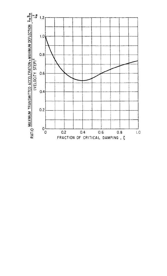
In Fig. 31.15 the parameter
¨
x
m
δ
m
/
˙
u
m
2
is plotted as a function of ζ. (As pointed out
with reference to Fig. 31.10,
¨
x
m
δ
m
/
˙
u
m
2
is an inverse measure of shock isolator effective-
ness.) Figure 31.15 shows that the presence of damping improves the energy storage
effectiveness of the isolator even beyond ζ=0.50. In the neighborhood ζ=0.40, the
parameter
¨
x
m
δ
m
/
˙
u
m
2
attains a minimum value of 0.52—only slightly above the theoret-
ical minimum of 0.50. This parameter has the value 1.00 for an undamped linear sys-
tem, and even higher values for a hardening spring (see Fig. 31.10). On the other hand,
¨
x
m
δ
m
/
˙
u
m
2
may approach 0.50 when a softening spring is used.
True viscous damping of the type considered above is difficult to attain except in
electrical or magnetic form. Fluid dampers which depend upon orifices or other con-
stricted passages to throttle the flow are likely to produce damping forces that vary
more nearly as the square of the velocity. Dry friction tends to provide damping
forces which are virtually independent of velocity. The analysis of response to a
velocity step in the presence of Coulomb friction is similar to that described in the
section entitled General Formulas—No Damping.
Example 31.1. Equipment weighing 40 lb and sufficiently stiff to be considered
rigid is to be protected from a shock consisting of a velocity step
˙
u
a
= 70 in./sec. The
maximum allowable acceleration is
¨
x
a
= 21g (g is the acceleration of gravity) and
available clearance limits the deflection to δ
a
= 0.70 in. Find isolator characteristics
for: linear spring, hardening spring, softening spring, and linear spring with viscous
damping.
Linear Spring. Taking the maximum velocity
˙
u
m
equal to the expected velocity
˙
u
a
and using Eqs. (31.18) and (31.11),
THEORY OF SHOCK ISOLATION 31.13
FIGURE 31.14 Dimensionless representation of maximum trans-
mitted acceleration
¨
x
m
for an isolator having a linear spring and vis-
cous damping.
8434_Harris_31_b.qxd 09/20/2001 12:33 PM Page 31.13
δ
m
=≤δ
a
or ω
n
≥=100 rad/sec
From Eqs. (31.19) and (31.12),
¨
x
m
=ω
n
˙
u
m
≤
¨
x
a
. Then
ω
n
≤= =116 rad/sec
Selecting a value in the middle of the permissible range gives ω
n
= 108 rad/sec [17.2
Hz]. The corresponding maximum isolator deflection is δ
m
= 0.65 in. and the maxi-
mum acceleration of the equipment is
¨
x
m
= 7580 in./sec
2
= 19.6g.The isolator stiffness
given by Eq. (31.16) is
k = mω
n
2
=×(108 rad/sec)
2
= 1210 lb/in.
If, as is usually the case, the isolation is provided by several individual isolators in
parallel, then the above value of k represents the sum of the stiffnesses of the indi-
vidual isolators.
Hardening Spring. The tangent elasticity represented by Eq. (31.20) is
assumed. Since the linear spring meets the specifications with only a small margin of
40 lb
386 in./sec
2
21 × 386 in./sec
2
70 in./sec
¨
x
a
˙
u
m
70 in./sec
0.70 in.
˙
u
m
ω
n
31.14 CHAPTER THIRTY-ONE
FIGURE 31.15 Dimensionless representation of energy absorption
capability of an isolator having a linear spring and viscous damping.
8434_Harris_31_b.qxd 09/20/2001 12:33 PM Page 31.14

safety, it is inferred that the poorer energy storage capacity of the hardening spring
shown by Fig. 31.10 will severely limit the permissible nonlinearity. Using the speci-
fied values as maxima,
== =1.16
From Fig. 31.10:
= 0.54; thus d ==1.30 in.
From Fig. 31.9:
= 0.58; thus ω
n
==93 rad/sec [14.8 Hz]
The initial spring stiffness k from Eq. (31.16) is
k = (93)
2
= 896 lb/in.
Because the selected linear spring provides a small margin of safety and the hard-
ening spring provides none, superficial comparison suggests that the former is supe-
rior. Various other considerations, such as compactness and stiffness along other
axes, may offset the apparent advantage of the linear spring. Moreover, a shock
more severe than that specified could cause the linear spring to bottom abruptly and
cause much greater acceleration of the equipment.
Softening Spring. The hyperbolic tangent elasticity represented by Eq. (31.23)
is assumed. The softening spring has high energy-storage capacity as shown by
Fig. 31.13. By working to sufficiently high values of δ
m
/d
1
, it is possible to utilize this
storage capacity to afford considerable overload capability. Choose
¨
x
m
= 20g and
δ
m
/d
1
= 3. From Fig. 31.13,
¨
x
m
δ
m
/
˙
u
m
2
= 0.645 at δ
m
/d
1
= 3. Then
δ
m
= 0.645 = 0.41 in. d
1
==0.137 in.
From Fig. 31.12,
˙
u
m
/ω
n
d
1
= 2.15 at δ
m
/d
1
= 3. Then
ω
n
==238 rad/sec [37.9 Hz]
The initial spring stiffness k from Eq. (31.16) is
k = (238)
2
= 5870 lb/in.
This initial stiffness is much greater than those found for the linear spring and
hardening spring.Accordingly, for small shocks (small
˙
u
m
) the isolator with the soft-
ening spring will induce much higher acceleration of the equipment than will those
40
386
70
2.15 × 0.137
δ
m
3
(70)
2
20 × 386
40
386
70
1.30 × 0.54
˙
u
m
ω
n
d
0.70
0.54
δ
m
d
(21 × 386) × 0.70
(70)
2
¨
x
a
δ
a
˙
u
a
2
¨
x
m
δ
m
˙
u
m
2
THEORY OF SHOCK ISOLATION 31.15
8434_Harris_31_b.qxd 09/20/2001 12:33 PM Page 31.15