Harris C.M., Piersol A.G. Harris Shock and vibration handbook
Подождите немного. Документ загружается.

In gated vibration analysis, the vibration signal is analyzed at various angles of
the crankshaft in order to cover a complete cycle of the machine in a three-
dimensional plot.
13
The analyzer is triggered by a once-per-cycle trigger signal; then
the delay after triggering is shifted to provide adequate overlap; this procedure con-
tinues until a complete cycle is covered. Note that each spectrum represents actually
an average over many machine cycles for one time delay. This process averages any
differences between machine cycles.
An alternative to gated vibration analysis is gated sound intensity analysis, which
is more suited to noise control and quality checks.
14
TREND ANALYSIS
Trend analysis makes use of graphs of a condition-related parameter versus time
(date or running hours) to determine when the parameter is likely to exceed a given
limit.The goal of a successful condition monitoring program is to predict the time of
an expected breakdown well in advance of its occurrence in order to shut down the
machine in ample time, to order spare parts, and thereby to minimize the shutdown
time. Since all vibration criteria indicate that equal changes on a log scale corre-
CONDITION MONITORING OF MACHINERY 16.23
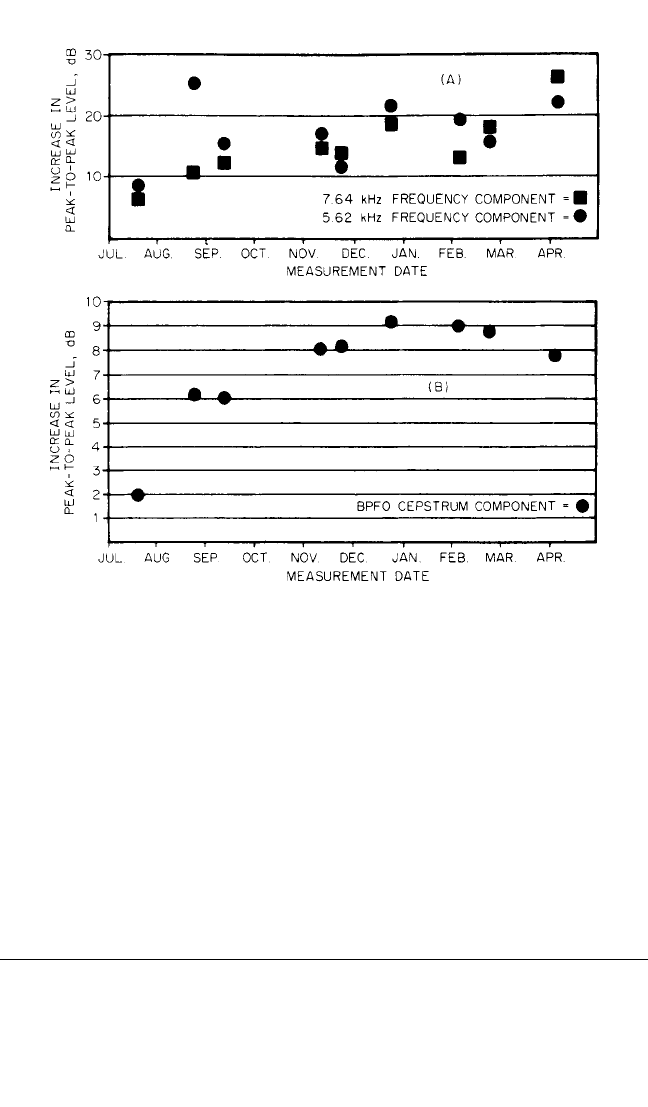
FIGURE 16.12 (A) Development of the fault illustrated in Fig. 16.13, using the har-
monic at 7640 Hz and the harmonic at 5620 Hz as the parameter. (B) The correspon-
ding trend curve using the cepstrum component as the parameter, showing a smooth
evolution.
10
8434_Harris_16_b.qxd 09/20/2001 12:16 PM Page 16.23

spond to equal changes in severity, data for a trend analysis should be plotted on a
logarithmic scale in decibels. A linear trend on a logarithmic scale is found occa-
sionally, but the actual trend may follow another course; for example, when the fault
feeds back on the rate of deterioration (e.g., gear wear), the trend, when plotted on
a logarithmic scale, may then be exponential. In some cases the fault changes sud-
denly in finite steps (for example, a spall caused by gradual subsurface fatigue), mak-
ing it very difficult to extrapolate to determine the date of the shutdown. To ensure
accurate trend analysis, the following precautions should be taken:
1. Determine a trend based on measurements of a parameter directly related to a
specific type of fault—not on measurements of overall levels.
2. Diagnose faults before attempting to interpret a trend curve in order to (a) select
the appropriate parameter for the type of fault which is being monitored (for
example, the parameter may be the level of an individual component, of a cep-
strum component, or of a selected frequency range) and (b) observe critically the
results of the trend analysis so as to determine if the linear or exponential inter-
polation is adequate.
3. Keep in mind that the best estimate of the lead time will be obtained by employ-
ing a trend of the most recent measurements.
USE OF COMPUTERS IN CONDITION
MONITORING PROGRAMS
Computers can be of great help in a condition monitoring program in handling, fil-
ing, and storing data and in performing tedious computations such as spectrum
comparison and trend analysis.A condition monitoring system which incorporates a
computer includes:
1. A recording device for storing the analog or digital time signals or frequency
spectra. In a permanently installed monitoring system, the analog time signal is
directly connected to the following items.
2. An analyzer with both fast Fourier transform (FFT) narrowband analysis and
advanced diagnostic techniques (zoom, cepstrum) for diagnostics.
3. A computer and appropriate software which provide (a) management of the
measurement program, including route mapping, storage of reference spectra/
cepstra, and new spectra/cepstra; (b) a comparison of spectra and a printout of
significant changes; and (c) trend analysis of any chosen parameter (individual
component or overall level in a given frequency range). In a permanent monitor-
ing system, the complete process (i.e., a new analysis) is performed automatically
at a predetermined rate, which is adjusted as the fault develops.
REFERENCES
1. Eshleman, R. L.: “Basic Machinery Vibrations,” VIPress, Clarendon Hills, Ill., 1999.
2. Mitchell, J. S.: “An Introduction to Machinery Analysis and Monitoring,” Penwell Publish-
ing Company, Tulsa, Okla., 1981.
16.24 CHAPTER SIXTEEN
8434_Harris_16_b.qxd 09/20/2001 12:16 PM Page 16.24

3. Downham, E., and R.Woods:“The Rationale of Monitoring Vibration in Rotating Machin-
ery in Continuously Operating Process Plant,” ASME paper no. 71-Vibr-96, 1971.
4. Sohre, J. S.: “Turbomachinery Problems and Their Correction,” chap. 7, in J. W. Sawyer and
K. Halberg (eds.), “Sawyer’s Turbomachinery Maintenance Handbooks,” vol. II, Turbo
International Pubn., 1981.
5. Bate, A. H.: “Vibration Diagnostics for Industrial Electric Motor-Drives,” Brüel and Kjaer
application note.
6. Kryter, R. C., and H. D. Haynes: “Condition Monitoring of Machinery Using Motor Cur-
rent Signature Analysis,” Sound and Vibration, September 1989.
7. Randall, R. B.:“A New Method of Modeling Gear Faults,” ASME paper no. 81-Set-10, June
1981.
8. Eshleman, R. L., “Machinery Vibration Analysis II Notes,” Vibration Institute, Willow-
brook, Ill., 2000.
9. Taylor, J. I., “The Vibration Analysis Handbook,” Vibration Consultants, Inc., Tampa, Fla.,
1994.
10. Bradshaw, P., and R. B. Randall: “Early Detection and Diagnosis of Machine Faults on the
Trans Alaska Pipeline,” MSA session, ASME Conference, Dearborn, Mich., September
11–14, 1983.
11. Courrech, J.: “New Techniques for Fault Diagnostics in Rolling Element Bearings,” Proc.
40th Meeting of the Mechanical Failure Preventive Group, National Bureau of Standards,
Gaithersburg, Md., April 16–18, 1985.
12. Randall, R. B., and Yujin, Gao, “Tracking changes in Modal Parameters by Curve Fitting
the Response Cepstrum.” 17th ISMR, K. U. Leuvan, September 23–25, 1992.
13. Courrech, J.: “Examples of the Application of Gated Vibration Analysis for the Detection
of Faults in Reciprocating Machines,” Noise and Vibration ’89 Conference, Singapore,
August 16–18, 1989.
14. Rasmussen, P., and T. L. Moller: “Gated Sound Intensity Measurements on a Diesel
Engine,” Brüel and Kjaer application note.
CONDITION MONITORING OF MACHINERY 16.25
8434_Harris_16_b.qxd 09/20/2001 12:16 PM Page 16.25

CHAPTER 17
STRAIN-GAGE
INSTRUMENTATION
Earl J. Wilson
INTRODUCTION
A strain-sensitive material is one whose electrical resistance is proportional to the
instantaneous spatial-average strain over its surface. Such materials are of two
types: metallic (i.e., foil or wire) or semiconductor (described in Chap. 12 under
Piezoresistive Accelerometers). When such a material is stretched, its length in-
creases and its cross-section decreases; consequently, there is an increase in its elec-
trical resistance. This change in resistance is a measure of its mechanical motion.
Thus, a strain gage is a device which uses change in electrical resistance to measure
strain.
The resistance strain gage may be employed in shock or vibration instrumenta-
tion in either of two ways. The strain gage may be the active element in a commer-
cial or special-purpose transducer or pickup, or it may be bonded directly to a
critical area on a vibrating member. Both of these applications are considered in this
chapter, together with a discussion of strain-gage types and characteristics, cements
and bonding techniques, circuitry for signal enhancement and temperature compen-
sation, and related aspects of strain-gage technology.
The electrical resistance strain gage discussed in this chapter is basically a
piece of very thin foil or fine wire which exhibits a change in resistance propor-
tional to the mechanical strain imposed on it. In order to handle such a delicate
filament, it is either mounted on, encapsulated in, or bonded to some type of car-
rier material and is known as the bonded strain gage. Bonded strain gages are
available in a wide range of sizes and resistances. Unbonded strain gages, where
the wire is free, are rarely used because of their limited frequency range and lack
of sensitivity.
The strain gage is used universally by stress analysts in the experimental deter-
mination of stresses. Since strain always accompanies vibration, the strain gage or
the principle by which it works is broadly applicable in the field of shock and vibra-
tion measurement. Here it serves to determine not only the magnitude of the strains
produced by the shock or vibration, but also the entire time-history of the event, no
matter how great the frequency of the phenomenon.
17.1
8434_Harris_17_b.qxd 09/20/2001 12:15 PM Page 17.1
BASIC STRAIN-GAGE THEORY AND PROPERTIES
The relationship between resistance change and strain in the foil or wire used in
strain-gage construction can be expressed as
=
or K = (17.1)
where K is defined as the gage factor of the foil or wire, ∆R is the resistance change due
to strain, R is the initial resistance, ∆L is the change in length, L is the original length
of the wire or foil, and ∆L/L is the unit strain to which the wire or foil is subjected.
Not all materials exhibit this strain-sensitivity effect, and different materials have
different gage factors. Filament materials in common use in strain gages are Con-
stantan (Ni 0.45, Cu 0.55), which has a gage factor of approximately +2.0; Iso-elastic
(Ni 0.36, Cu 0.08, Fe 0.52, and Mo 0.005), which has a gage factor of about +3.5; and
modified Karma (Ni 0.75, Cr 0.20, plus additions), which has a gage factor of +2.1.
STRAIN-GAGE CONSTRUCTION
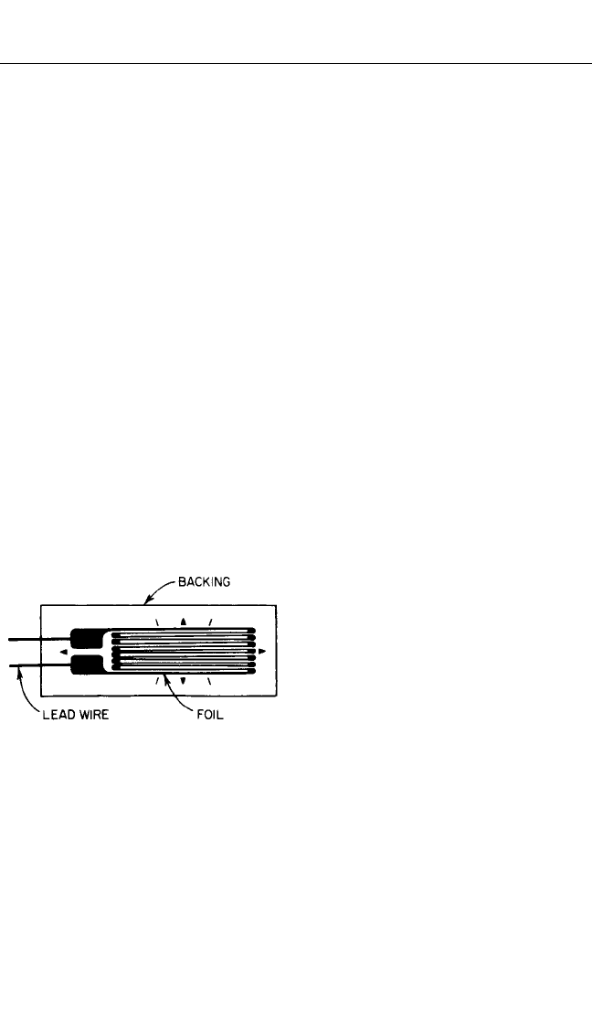
Most strain gages are of foil construction, illustrated in Fig. 17.1, although fine-wire
strain gages are used for special purposes, such as at high temperatures. Foil strain
gages are usually made by a printed-circuit process.
Since the foil used in a strain gage must be very fine or thin to have a sufficiently
high electrical resistance (usually between 60 and 350 ohms), it is difficult to handle.
For example, the foil used in gages is
often about 0.1 mil in thickness. Some
use has been made of wire filaments in
strain gages, but this type of gage is sel-
dom used except in special or high-
temperature applications. In order to
handle this foil, it must be provided with
a carrier medium or backing material,
usually a piece of paper, plastic, or
epoxy. The backing material performs
another very important function in addi-
tion to providing ease of handling and
simplicity of application. The cement
provides so much lateral resistance to the foil that it can be shortened significantly
without buckling; then compressive as well as tensile strains can be measured. Lead
wires or connection terminals are often provided on foil gages, as illustrated in the
typical foil gage shown in Fig. 17.1.A protective coating,recommended or supplied by
the manufacturer, is usually applied over the strain gage, especially where the lead
wires are attached.
TRANSVERSE SENSITIVITY
Because of its construction, a portion of the foil in each gage lies in the transverse
direction and will respond to transverse strain.
1
Therefore the gage factor K of a
∆R/R
∆L/L
∆R
R
1
K
∆L
L
17.2 CHAPTER SEVENTEEN
FIGURE 17.1 Typical construction of a foil
strain gage.
8434_Harris_17_b.qxd 09/20/2001 12:15 PM Page 17.2
gage* is always slightly smaller than the gage factor of the material of which it is
fabricated. One of the desirable features of foil-type gages is their low transverse
sensitivity. In this case, the gage consists of a flat foil grid; a sufficiently large
amount of the foil is left at the ends of each strand to reduce the transverse sensi-
tivity of the gage to one-half the value for wire gages for some types and to essen-
tially zero for others.
TEMPERATURE EFFECTS
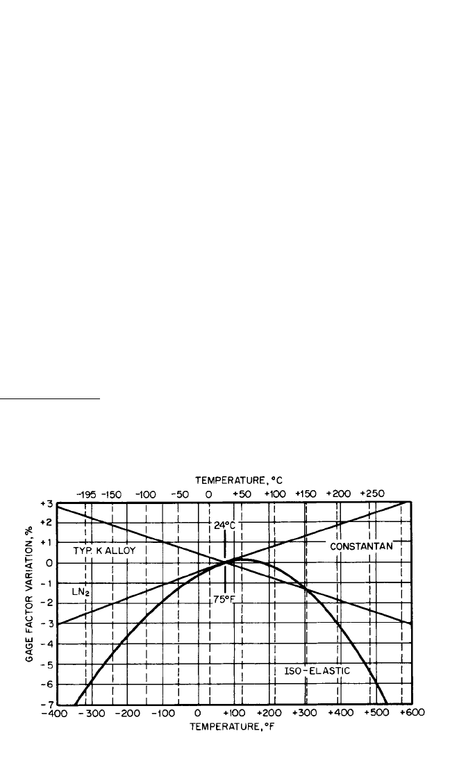
The effects of temperature on the gage factor of several alloys are illustrated in Figs.
17.2 and 17.3. When a bonded strain gage is used in measurements, any change in
resistance in the strain-gage measurement system is interpreted as resulting from
a strain. If thermal expansion is not induced, then this change will result from a
mechanical strain. However, if thermal expansion is induced, then there will be a
change in resistance resulting from the mechanical strain, and in addition, there will
be a change in resistance resulting from the response of the strain gage to changes in
temperature. The strain indication which results from such a temperature effect is
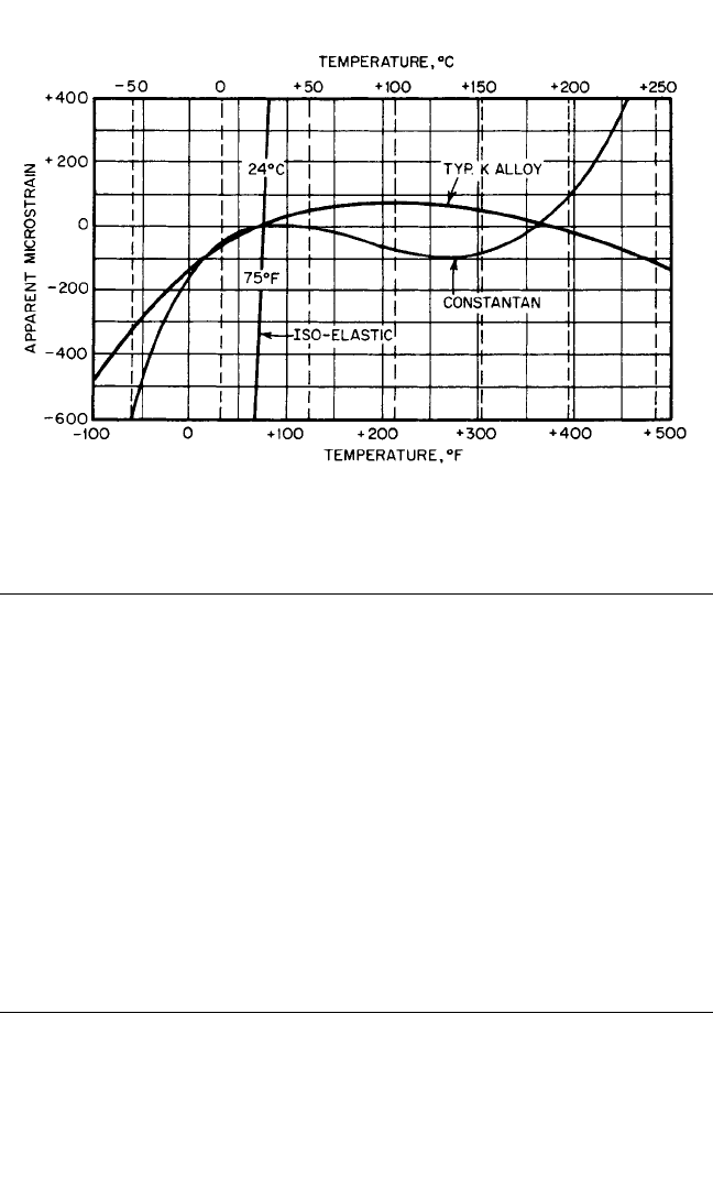
known as an “apparent strain.” Figure 17.3 shows typical apparent strain for three
commonly used alloys. This effect is usually negligible in the measurement of
dynamic strains, since the readout instrument associated with the strain gage usually
does not respond to static or slow changes in its resistance. However, in the meas-
urement of static strains, the effects of temperature represent the largest potential
source of error and require some form of temperature compensation.
2
It is therefore
important to know the temperature at which a strain gage is used.
STRAIN-GAGE INSTRUMENTATION 17.3
FIGURE 17.2 Typical variation in the gage factor of strain-gage alloys as a function of
temperature.
* In determining the gage factor of the gage, it is assumed that the gage is mounted on a material having a
Poisson’s ratio of 0.285 and subjected to uniaxial stress in the direction of the gage axis.
8434_Harris_17_b.qxd 09/20/2001 12:15 PM Page 17.3
STRAIN-GAGE CLASSIFICATIONS
Strain gages are classified in several ways. One classification cites the purpose for
which the gage is to be used, that is, for static or dynamic strain measurement. Static
gages are often made up with Constantan foil (a copper-nickel alloy), which has
a minimum change of resistance with temperature. Dynamic strain gages occasion-
ally are made up with Iso-elastic foil (iron-nickel-chrome alloy), which provides a
greater gage factor than Constantan. Another common alloy used in strain gages is
Karma, an alloy primarily of nickel and chrome. The dynamic gages, while having a
much greater resistance change for a given strain than the static gages, also are much
more sensitive to changes in temperature. They are used only where the phenome-
non to be measured is so short in time duration that no temperature change of any
consequence can occur during the time of measurement. Gages also are available for
the measurement of very large strains (up to 20 percent) occurring in the plastic
region of the material, as distinguished from the more common gages which are used
to measure elastic strains (up to 1 percent).
STRAIN-GAGE SELECTION CONSIDERATIONS
In the case of shock measurements, a transient may be applied to the structure that
is under investigation only once, or it may be repetitive. Shock is of very short time
duration, and the problem of temperature compensation is nonexistent because in
most cases the temperature does not have time to change during the impact. For this
reason a dynamic-type gage usually can be employed for the measurement of shock.
This type of gage has the advantage of a higher gage factor than the static gage, and
so it will provide the greatest possible electrical signal for a given strain.
17.4 CHAPTER SEVENTEEN
FIGURE 17.3 Typical apparent strain for three alloys commonly used in strain gages. These
data are based on an instrument gage factor of 2.00.
8434_Harris_17_b.qxd 09/20/2001 12:15 PM Page 17.4
For vibration measurement, the type of gage selected is dependent on the kind of
information desired. If only the frequency of vibration and the magnitude of the
cyclic stresses are desired, dynamic-type gages can be used since temperature
changes will not affect the results obtained unless the temperature fluctuates at the
same rate as the stress. If, however, a measurement of the static or slowly varying
component of the stress is also to be determined (i.e., if the absolute values of the
stresses are desired), a static-type gage must be employed. Since changes in temper-
ature will affect the gage reading, temperature compensation must be incorporated
to obtain true values of stress.
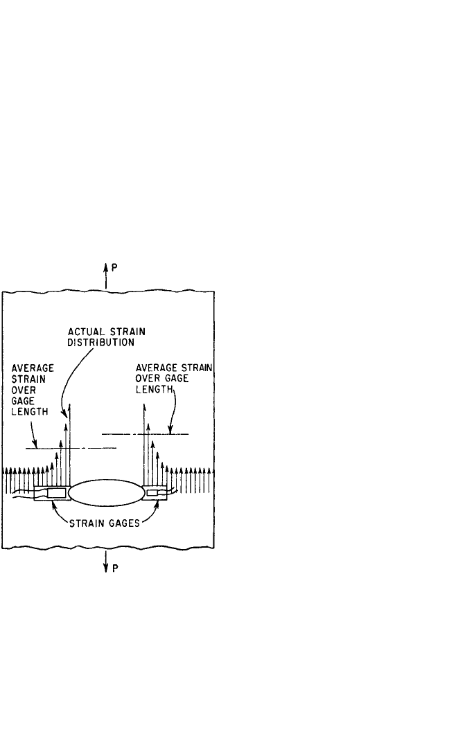
Gage selection is dependent on the space limitation and steepness of strain gradi-
ent in any region. The strain gage indicates the average strain over the length of the
gage; in a region of steep strain gradient, this indicated value may be much less than
the maximum strain.The shorter the gage used in such a region, the closer is the gage
indication to the maximum strain (Fig. 17.4). However, two possible objectives must
be considered quite carefully in selecting a gage for a particular installation: (1) the
determination of the frequency of vibra-
tion, or comparison of relative ampli-
tudes and frequencies with different
conditions of excitation, and (2) the
determination of the maximum stress
pattern resulting from the vibration set
up. In the first case there is considerable
freedom with regard to the location of
the gage on the structure, and therefore
with the selection of the gage itself. In
the second case severe restrictions exist
in regard to the region of application of
the gage and its possible dimensions. In
general, very short gage-length gages are
more difficult to apply properly. There-
fore it is desirable to employ gage
lengths of
1
⁄4 in. whenever possible. When
the actual magnitude of the maximum
stress resulting from shock or vibration is
to be determined, a much more compli-
cated system of gages must be employed.
A single gage can be used in only the
very limited case where a stress exists in
one direction only, and that direction
must be known. If stresses exist in sev-
eral directions, or if the direction of a
singly existing stress is unknown, a
strain-gage rosette consisting of three or
more gages must be employed.
3
PHYSICAL ENVIRONMENT
The physical environment of the applied gage is an important factor which must be
considered in gage selection and protective treatment. Temperature, pressure, humid-
ity, oil, corrosive acid, abrasive action, and possible electromagnetic, neutron, and radi-
ation fields are conditions which affect the choice of gage and its required protection.
STRAIN-GAGE INSTRUMENTATION 17.5
FIGURE 17.4 Effect of gage length on indi-
cated strain in the presence of a severe strain
gradient. The shorter gage on the right indicates
a higher strain. An infinitesimal gage length
would be necessary to indicate the peak strain.
8434_Harris_17_b.qxd 09/20/2001 12:15 PM Page 17.5

If high temperatures (up to 500°F or 260°C) are to be encountered, a Bakelite or other
high-temperature-type gage must be selected. If even higher temperatures must be
withstood, a ceramic-type gage should be employed. Gages of this sort are used at
temperatures as high as 2000°F (1100°C). If the temperature never exceeds 200°F
(95°C), however, any type of gage can be used.
ACCURACY CONSIDERATIONS
Gages must be selected with regard to the desired precision of the results. If only the
frequency of the vibration or the duration of a shock wave is required, almost any
gage, properly chosen for the temperature and humidity conditions to be encoun-
tered, gives quite satisfactory results. However, if the magnitude of the stresses pro-
duced is to be determined in addition, then considerable care must be exercised to
select the proper gage to obtain the desired results. Not only must the gage be the
proper one to portray the encountered strain faithfully, but precautions must be
taken to install the gage correctly.
The testing “environment” can affect strain-gage accuracy in many ways. Magne-
tostrictive effects,
4
hydrostatic pressure,
5
nuclear radiation,
6
and high humidity are
examples of conditions that may cause large strain-gage errors. Creep, drift, and
fatigue life in the gages themselves may be important. In most normal environments
these errors are either small or undetectable. Whenever unusual or harsh environ-
ments are encountered, it is wise to consult the strain-gage manufacturer to obtain
recommendations for gage systems and estimates of expected accuracies.
BONDING TECHNIQUES
The proper functioning of a strain gage is completely dependent on the bond
which holds it to the structure undergoing test. If the bond does not faithfully
transmit the strain from the test piece to the wire or foil of the gage, the results
obtained cannot be accurate. Failure to bond over even a minute area of the gage
will result in incorrect strain indications. The greatest weakness in the entire tech-
nique of strain measurement by means of wire or foil gages is in the bonding of the
gage to the test piece. Usually, the manufacturer of the strain gages will recom-
mend cements which are compatible with their use and will provide instructions
for their proper installation.
In order to achieve a good bond, it is essential that the surface to which the gage
is bonded be chemically clean. Various cements used for this purpose are described
in Chap. 15. It is advisable to protect the bonded strain gage with a coating recom-
mended by the manufacturer for the environment in which the strain gage is to
operate.
STRAIN-GAGE MEASUREMENTS
The resistance strain gage,
7
because of its inherent linearity, very small mass, wide
frequency response (from zero to more than 100,000 Hz), general versatility, and
ease of installation in a variety of applications, is an ideal sensitive component for
electrical transducers for use in shock and vibration instrumentation.
8
The Wheat-
17.6 CHAPTER SEVENTEEN
8434_Harris_17_b.qxd 09/20/2001 12:15 PM Page 17.6

stone bridge circuit, described in a subsequent section, can be used to extend the ver-
satility of the strain gage to still broader applications by performing mathematical
operations on the strain-gage output signals. The combination of these two devices
can be used effectively for the measurement of acceleration, displacement, force,
torque, pressure, and similar mechanical variables. Other useful attributes include
the capacity for separation of forces and moments, vector resolution of forces and
accelerations, and cancellation of undesired vector components.
The usual technique for employing a strain gage as a transducing element is to
attach the gage to some form of mechanical member which is loaded or deformed in
such a manner as to produce a signal in the strain gage proportional to the variable
being measured. The mechanical member can be utilized in tension, compression,
bending, torsion, or any combination of these. All strain-gage-actuated transducers
can be considered as either force- or torque-measuring instruments.Any mechanical
variable which can be predictably manifested as a force or a couple can be instru-
mented with strain gages.
There are a number of precautions which should be observed in the design and
construction of custom-made strain-gage transducers.
9
First, the elastic member on
which the strain gage is to be mounted should be characterized by very low mechan-
ical hysteresis and should have a high ratio of proportional limit to modulus of elas-
ticity (i.e., as large an elastic strain as possible). Although aluminum, bronze, and
other metals are often employed for this purpose, steel is the most common mate-
rial. An alloy steel such as SAE 4340, heat-treated to a hardness of RC 40, will ordi-
narily function very satisfactorily.
The physical form of the elastic member and the location of the strain gages
thereon are not subject to specific recommendation, but vary with the special
requirements of each individual instrumentation task. When no such requirements
exist, a standard commercial transducer ordinarily should be used. In general, the
shape of the member should be such as to (1) allow adequate space for mounting
strain gages (preferably in regions of zero or near-zero strain gradient), (2) provide
the desired natural frequency, (3) produce a strain in the gages which is great enough
at low values of the measured variable to result in an output signal readily subject to
accurate indication or recording, and not so great as to cause nonlinearities or
abbreviated gage life at peak load values, (4) provide temperature compensation
and/or signal augmentation (as described in a subsequent section) whenever feasi-
ble, and (5) allow for simplicity of machining, ease of gage attachment and wiring,
and, if necessary, protection of the gages.
The strain gages should be cemented to the elastic member with the usual care
and cleanliness necessary in all strain-gage applications, special attention being
given to minimizing the bulk of the installation if the added mass is significant to the
frequency response of the instrument. Other considerations vital to successful
strain-gage-application technique are described elsewhere in this chapter.
DISPLACEMENT MEASUREMENT
Measurement of displacement with strain gages can be accomplished by exploiting
the fact that the deflection of a beam or other loaded mechanical member is ordi-
narily proportional to the strain at every point in the member as long as all strains
are within the elastic limit.
For small displacements at low frequencies, a cantilever beam arranged as shown
in Fig. 17.5 can be employed. The beam should be mounted with sufficient preload
on the moving surface that continuous contact at the maximum operating frequency
STRAIN-GAGE INSTRUMENTATION 17.7
8434_Harris_17_b.qxd 09/20/2001 12:15 PM Page 17.7