Harris C.M., Piersol A.G. Harris Shock and vibration handbook
Подождите немного. Документ загружается.


ESTABLISHING A CONDITION MONITORING
PROGRAM
A condition monitoring program may be established to check the satisfactory oper-
ation of a single machine or, more usually, it is established to check the operation of
a number of machines, perhaps all the machines in an entire plant. The following
steps are usually considered in the establishment of such a program, depending on
the type of machine and impact of failure of operation machines might have.
Step 1. Determine the type of condition monitoring system, described in the pre-
ceding section, that best meets the needs of the plant.
Step 2. Make a list of all of the machines to be monitored (see, for example, Table
16.1), based on the importance of these machines in the production line.
Step 3. Tabulate the characteristics of the machines that are important in conduct-
ing vibration analyses of the machines of step 2. These characteristics are associated
with machine construction such as the natural frequencies of shafts, casings, and
pedestals, and operational and defect responses. A tabulation of machine frequen-
cies is important because fault analysis is conducted (Table 16.2) by matching
machine frequencies to measured frequencies appearing in a spectrum. The follow-
ing machine characteristics provide the necessary information for fault analysis.
●
Shaft rotational speeds, bearing defect frequencies, number of teeth in gears, num-
ber of vanes and blades in pumps and fans, number of motor poles, and number of
stator slots and rotor bars.
●
Vibratory forces such as misalignment, mass unbalance, and reciprocating masses.
●
Vibration responses due to process changes, such as temperature and pressure.
●
Fault responses associated with specific machine types, such as motors, pumps, and
fans.
●
Sensitivity to instability in components, such as fluid film bearings and seals due to
wear and clearance.
●
Loads or changes in operating conditions.
●
Effects of mass unbalance, misalignment, distortion, and other malfunction/defect
excitations on vibration response.
CONDITION MONITORING OF MACHINERY 16.3
TABLE 16.1 Machinery Classification for Monitoring
Machinery classification Result of failure
Critical Unexpected shutdown or failure causes significant
production loss.
Interrupts production Unexpected shutdown or failure causes minor
interruptions in production.
Causes inconvenience Inconvenience in operation, but no interruption
in production.
Noncritical Production is not affected by failure.
8434_Harris_16_b.qxd 09/20/2001 12:16 PM Page 16.3
Step 4. Select the most appropriate vibration measurement parameter. When an
accelerometer is employed as the sensing device in a condition monitoring system,
the resulting acceleration signal can be electronically integrated to obtain velocity or
displacement, so any one of these three parameters may be used in measurements.
The appropriate parameter may be selected by application of the following simple
rule: Use the parameter which provides the “flattest” spectrum. The flattest spectrum
requires the least dynamic range from the instrumentation which follows the trans-
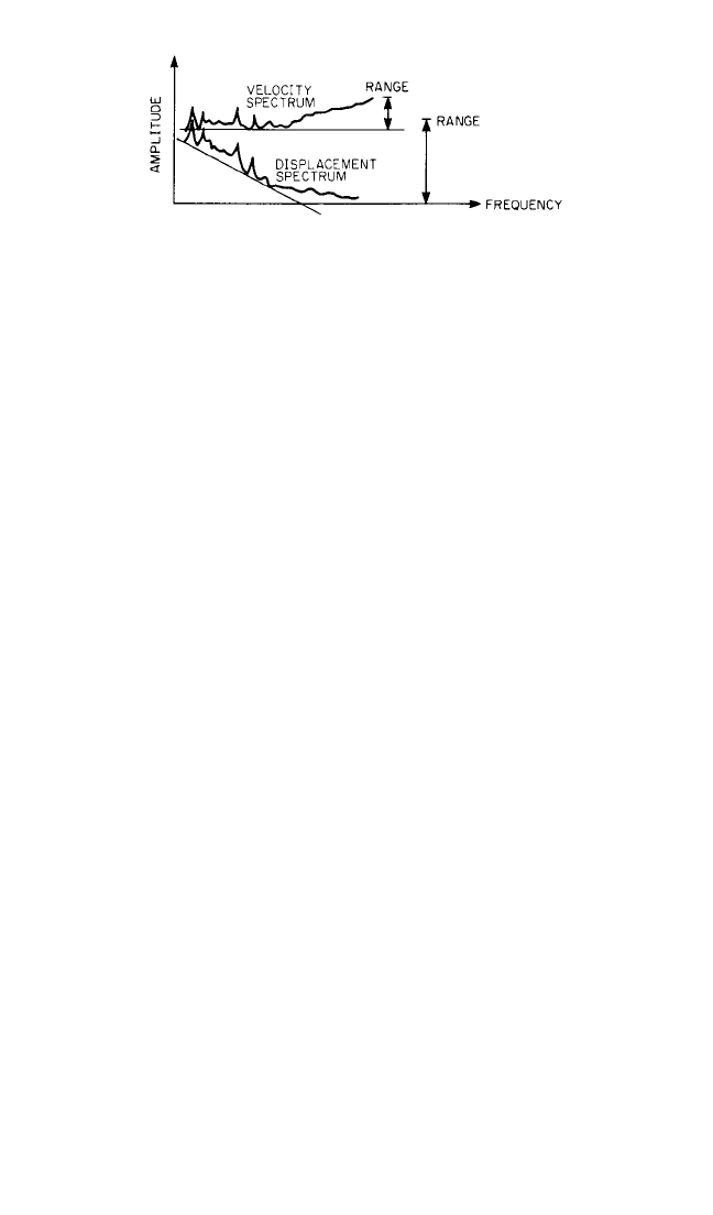
ducer. For example, Fig. 16.1 shows a velocity spectrum and a displacement spectrum
obtained under identical conditions. The dynamic range (i.e., the range from the
highest to the lowest signal level) required to measure the displacement spectrum is
much larger than the range for the velocity spectrum; it may even exceed the avail-
able dynamic range of the instrumentation. Therefore, according to this rule, veloc-
ity measurements should be selected.
The flattest spectrum rule applies only to the frequency range of interest. There-
fore, the parameter selection, to some extent, depends on the type of machine and
the type of faults considered.
Step 5. Select one of the following vibration pickups that will best meet the require-
ments of step 4.
Displacement Transducer. A displacement transducer is a transducer that con-
verts an input mechanical displacement into an electrical output that is proportional
to the input displacement. Displacement transducer of the eddy-current type
(described in Chap. 12), which have noncontacting probes, are commonly used to
measure the relative motion between a shaft and its bearings. This information can
be related directly to physical values such as mechanical clearance or oil-film thick-
ness, e.g., it can give an indication of incipient rubbing. Shaft vibration provides
information about the current condition of a machine and is principally used in per-
manent monitoring systems, which immediately shut the machine down in the event
of trouble. The use of displacement transducers is essential in machinery having
journal bearings. However, proximity probe transducers (1) usually are difficult to
calibrate absolutely, (2) have limited dynamic range because of the influence of elec-
trical and mechanical runout on the shaft, and (3) have a limited high-frequency
range.
Accelerometers and Velocity Pickup. Pickups of this type, described in Chap.
12, are usually lightweight and rugged. They are always used for detecting faults
which occur at high frequencies (say, above 1000 Hz), for example, to detect rolling-
element bearing deterioration or gearbox wear. Acceleration measurements of
bearing vibration will provide very early warning of incipient faults in a machine.
16.4 CHAPTER SIXTEEN
FIGURE 16.1 Displacement and velocity spectra
obtained under identical conditions. The velocity spec-
trum requires a smaller dynamic range of the equipment
which follows the transducer.Therefore, it is preferable.
8434_Harris_16_b.qxd 09/20/2001 12:16 PM Page 16.4

Step 6. Select the measurement locations. When a periodic (off-line) monitoring
system is employed, the number of points at which measurements are made is lim-
ited only by the requirement for keeping measurement time to a minimum. As a
general rule, bearing vibration measurements are made in the radial direction on
each accessible bearing, and in the axial direction on thrust bearings. It is not usually
necessary to measure bearing vibration in both the horizontal and the vertical direc-
tion, since both measurements give the same information regarding the forces
within the machine; this information is merely transmitted through two different
transmission paths. This applies for detecting developing faults. It will later be seen,
however, that in order subsequently to diagnose the origin of the impending fault,
measurements in both the horizontal and the vertical direction may give valuable
information.When measuring shaft vibrations with permanently mounted proximity
transducers, it is convenient to use two probes on each bearing, located at 90° from
each other, thereby providing an indication of the orbit of the shaft within the bear-
ing.Axial displacement transducers, programmed to shut the machine down on pre-
set levels, are mounted where a thrust measurement will protect the machine
rotating parts, such as blades, from rubbing the stationary casing due to fault-
induced axial forces.
When a permanent (on-line) monitoring system is employed using a seismic
pickup, the number of measurement points usually is minimized for reasons of
economy. Selection must be made following a study of the vibration spectra of dif-
ferent bearings in order to locate those points where all significant components
related to the different expected faults are transmitted at measurable vibration
levels if full spectrum comparison is performed. If only broadband measurements
are monitored, then a further requirement is that all frequency components
related to the expected faults must be of approximately the same level within the
selected frequency range. Otherwise, measurements must be made in selected fre-
quency bands.
Step 7. Select the time interval between measurements. The selection of the time
interval between measurements requires knowledge of the specific machine. Some
machines develop faults quickly, and others run trouble-free for years. A compro-
mise must be found between the safety of the system and the time taken for meas-
urements and analysis. Measurements should be made frequently in the initial stages
of a condition monitoring program to ensure that the vibration levels measured are
stable and that no fault is already developing.When a significant change is detected,
the time interval between measurements should be reduced sufficiently so as not to
risk a breakdown before the next measurement. The trend curve will help in deter-
mining when the next measurement should be performed.
Step 8. Establish an optimum sequence of data acquisition. The sequence in which
data acquired in a condition monitoring program must be planned so that the data
are acquired efficiently. For example, the data collection may be planned on the
basis of plant layout, on the type of data required, or on the sequence of components
in the machine train, from driver to driven components.
FAULT DETECTION IN ROTATING MACHINERY
It is highly desirable to be able to detect all types of faults likely to occur during the
operation of rotating machinery. Such faults range from vibrations at very low fre-
CONDITION MONITORING OF MACHINERY 16.5
8434_Harris_16_b.qxd 09/20/2001 12:16 PM Page 16.5

quencies (subsynchronous components indicating looseness, oil whirl, faulty belt
drive, etc.) to vibrations at very high frequencies (tooth-meshing frequencies, blade-
passing frequencies, frequencies of structural resonances excited by faulty rolling-
element bearings, etc.). Such detection should be applicable to the complete range of
machines in a plant, which operate from very low to very high speed. This requires
the selection of equipment and analysis techniques which cover a very broad fre-
quency range.
Measurements of absolute vibration levels of bearings provide no indication of
the machine’s condition, since they are influenced by the transmission path
between the force and the measurement point, which may amplify some frequen-
cies and attenuate others. Bearing vibration levels change from one measurement
point to another on a given machine, since the transmission paths are different; they
also change for the same reason from machine to machine for measurements made
at the same measurement point.
3
Therefore, in estimating the condition of a
machine, it is essential to monitor changes in vibration from a reference value
established when the machine was known to be in good condition. Changes are
expressed as a ratio or, more commonly, as a change of level, i.e., the logarithm of a
ratio, in decibels.
The objective of condition monitoring of a machine is to predict a fault well in
advance of its occurrence. Therefore, a measurement of the overall vibration level
will not provide successful prediction because the highest vibration component
within the overall frequency range will dominate the measurement. This is illus-
trated in Fig. 16.2, which shows an example where overall measurements of the
vibration velocity resulted in an incorrect prediction with an overestimate of the
lead time. The early detection of faults in machinery can be made successfully only
by comparison with a reference spectrum. This section compares types of spectrum
analysis for this purpose.
Condition monitoring techniques employed during transient operating condi-
tions of the machine (i.e., when the machine is running up to full speed or slowing
down from full speed) differ significantly from the techniques employed during
steady-state operating conditions. Therefore it is essential that a careful investiga-
tion be carried out to ensure that the condition monitoring technique selected is
appropriate for the conditions of measurement.
FALSE ALARMS
Changes in machinery vibration may result from a number of causes which are not
necessarily related to the deterioration of the machine. For example, a change in
speed of the machine or a change in the load on the machine usually greatly modi-
fies the relative amplitudes of the different components of vibration at a fixed trans-
ducer location or modifies the relative pattern of vibration at different locations.
Depending on the criteria used for fault detection, such changes may result in a false
indication of deterioration of the machine. Appropriate selection of the technique
employed can avoid such false alarms.
HOW SPECTRUM CHANGES ARE RELATED
TO THE CONDITION OF A MACHINE
To obtain information about changes in condition of a machine, vibration spectra
should be compared only for similar operating conditions. The influence of operat-
16.6 CHAPTER SIXTEEN
8434_Harris_16_b.qxd 09/20/2001 12:16 PM Page 16.6
ing condition of the machine (such as machine speed, load, and temperature) on the
vibration parameter being measured varies greatly for different types of machines.
Speed changes of up to 10 per cent usually can be compensated for, and spectra can
be compared. If the speed changes are greater than this value, the operating condi-
tion of the machine should be considered to be different and a new reference spec-
trum used as a basis of comparison. The reference spectrum need not be measured
when the machine is new (after allowing for a run-in period). The reference spec-
CONDITION MONITORING OF MACHINERY 16.7
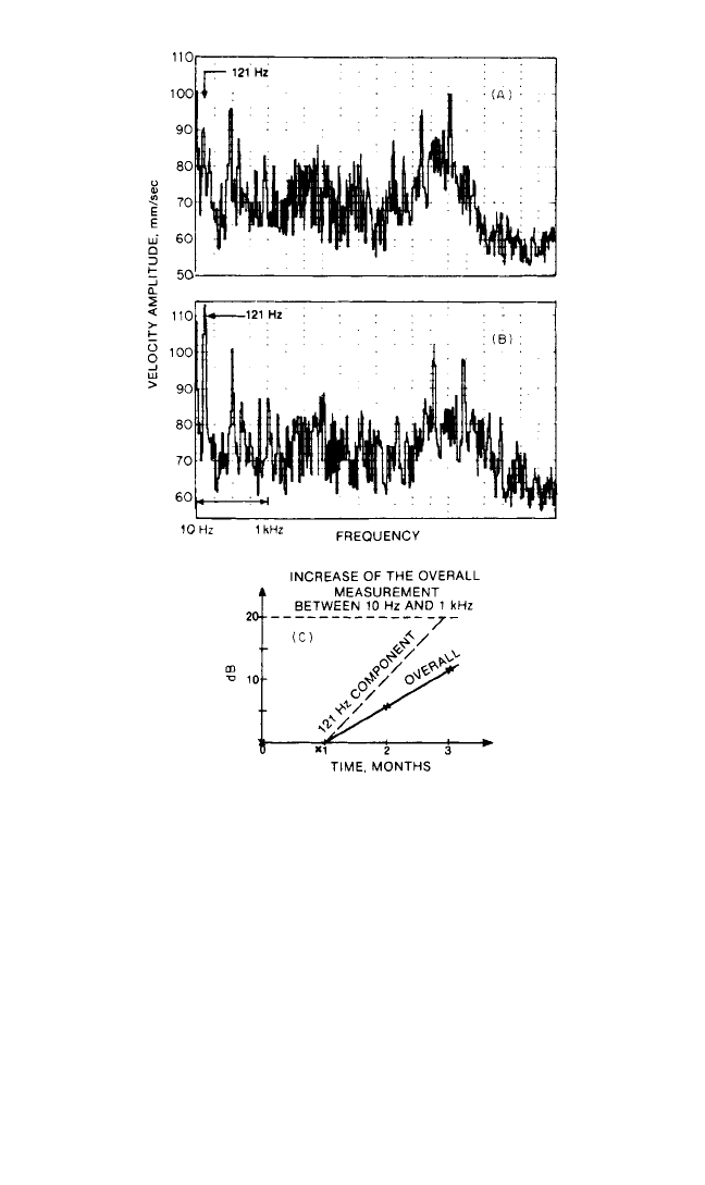
FIGURE 16.2 Trend analysis performed on an overall
measurement and on an individual component. (A) The
velocity spectrum of vibration measured on a gearbox after
installation. Note the high amplitude of the 480-Hz compo-
nent, dominating the reference spectrum. (B) The velocity
spectrum 3 months later. Note the dramatic increase in the
121-Hz component, which corresponds to the output shaft
speed of the gearbox. (C) Curves comparing the increase in
the 121-Hz component in the velocity spectrum; the
increase in overall velocity in the band from 10 to 1000 Hz
indicates a developing fault.
8434_Harris_16_b.qxd 09/20/2001 12:16 PM Page 16.7

trum can be determined at any time during the life of a machine provided the vibra-
tions are stable, since a stable spectrum is a sign of stable operation of the machine.
The principal difficulty is to establish when changes in the spectrum are sufficiently
large to warrant stopping the machine.
Most national and international standards for the measurement of bearing vibra-
tion do not consider frequency spectra; instead, they give values for vibration
changes of the rms value of the velocity amplitude from 10 to 1000 Hz (or 10,000 Hz)
for machines in good and bad condition. These ratios have successfully been trans-
posed to characteristic components in the vibration spectrum such as unbalance or
frequency. Usually, a change in the bearing vibration amplitude (measured in terms
of acceleration, velocity, or displacement) on any characteristic component from the
spectrum by a factor of 2 to 2.5 (6 to 8 dB in vibration level) is considered significant;
a change by a factor of 8 to 10 (18 to 20 dB in vibration level) is considered critical,
unless specified otherwise by the manufacturer. Limits for shaft vibration measure-
ments, giving the relative motion of the shaft inside the bearing, directly relate to
physical bearing clearance in the machine.The required time interval between meas-
urements varies greatly from one machine to another and depends directly on the
expected mean time between failure and the deterioration rate of the expected fail-
ures; therefore, measurements should be made more frequently as soon as incipient
deterioration is noticed.
Successful fault detection in machinery is the first step toward a successful condi-
tion monitoring program. Early recognition of deterioration is the key to valuable
fault diagnosis and efficient trend analysis. Consequently, this phase of condition
monitoring should not be neglected, although sometimes it may seem tedious.
SPECTRUM INTERPRETATION
AND FAULT DIAGNOSIS
Commercially available fast Fourier transform analyzers provide a suitable tool for
spectrum interpretation. They provide constant bandwidth (on a linear frequency
scale), and, by means of zoom or extended lines of resolution, they also provide very
high resolution in any frequency range of interest.This permits (1) early recognition
and separation of harmonic patterns or sideband patterns and (2) separation of
closely spaced individual components. Fast Fourier transform analyzers also may
provide diagnostic tools such as synchronous time averaging, cepstrum analysis,
and/or use of the Hilbert transform for amplitude and phase demodulation (see
Chap. 13).
Table 16.2 classifies different types of faults and indicates at which frequency the
faults are displayed in a vibration spectrum.Although such a table is of considerable
help in spectrum interpretation, any such simplified presentation must be used with
care, as illustrated by the examples considered below. The various faults can be clas-
sified according to their spectral components, as follows.
SUBSYNCHRONOUS COMPONENTS
Subsynchronous components of vibration (at frequencies below the rotational
speed of the machine) usually occur where sleeve bearings are used. The most com-
mon are the vibrations due to oil whirl, hysteresis whirl, resonant whirl, or mechani-
16.8 CHAPTER SIXTEEN
8434_Harris_16_b.qxd 09/20/2001 12:16 PM Page 16.8

cal looseness. These types of instability and nonlinear behavior are described in
detail in Ref. 4. Figure 16.3 shows a spectrum measured on the journal bearing of a
centrifugal compressor with mechanical looseness. A characteristic pattern of half-
order harmonics of rotation speed can be clearly seen. Figure 16.4 shows a spectrum
of the journal bearing of a pump in which a developing oil whirl shows up clearly at
21 Hz (42 percent of the rotation speed) and its second harmonic.
Both examples clearly indicate how the use of a linear frequency scale facilitates
the diagnosis of the fault by providing a clear indication of the different types of
harmonic patterns. High resolution is required to separate a half-order harmonic
component due to looseness (exactly 50 percent of rotation speed) from a compo-
nent due to oil whirl (42 to 48 percent of rotation speed).
LOW HARMONICS OF ROTATIONAL SPEED
Low harmonics of the rotational speed are generated by shaft unbalance, misalign-
ment, and eccentricity, as well as cracks in shafts and bent shafts. These various faults
may be difficult to distinguish, since they are mechanically related. A bad coupling
may result in misalignment. A bent shaft results in unbalance. Even a well-known
and well-defined fault such as unbalance may give misleading vibration components.
The exciting fault due to eccentric masses is a centrifugal force (thus radial) rotating
at the shaft speed and is therefore expected to result in a component in the vibration
spectrum at the machine speed and in the radial direction. However, dynamic unbal-
ance may also result in a rocking motion and consequently in vibration in both radial
and axial directions. In the same way, if there is a nonlinear transmission path from
the point where the force is applied to the point of measurement, a rise in the har-
monics of the rotation speed can be observed in the vibration spectrum, due to dis-
tortion of the signal.
The phase relationship between bearings provides essential information for dif-
ferentiating these various types of faults. As an example, unbalance will generate a
rotating force, and therefore the phase relationship between bearings can be
expected to be identical in both horizontal and vertical directions (in the absence of
resonances). For mass unbalance, the phase difference between a vertical and hori-
zontal transducer is 90° on the same bearing. Misalignment, however, does not cre-
ate a rotating force, and thus the phase relationship between bearings in both
vertical and horizontal directions can be vastly different.
HARMONICS OF THE POWER LINE FREQUENCY
Vibrational components, which are related to the frequency of the power line or
variable frequency drive, or to the difference between the synchronous frequency
and the rotational speed, occur in electric machines such as induction motors or gen-
erators.These vibrations are due to electromagnetically induced forces.These forces,
which occur in the case of a malfunction in the electric machine, are related to the air
gap between the rotor and the stator and to the current. The faults on the electric
machine are due either to the stator (called stationary faults) or to the rotor (called
rotating faults). They may originate from either a variation in the air gap or a varia-
tion in the current. Table 16.3 summarizes how these various faults show up in the
low-frequency range of the vibration spectrum.
5
Figure 16.5 shows a vibration signal measured on the rolling-element bearing of
an asynchronous electric motor. By zooming in the region of the high-level 100-Hz
CONDITION MONITORING OF MACHINERY 16.9
8434_Harris_16_b.qxd 09/20/2001 12:16 PM Page 16.9

TABLE 16.2 A Vibration Troubleshooting Chart
Frequency of dominant vibration,
Nature of fault Hz = rpm/60 Direction Remarks
Rotating members out of 1 × rpm Radial A common cause of excess vibration in machinery
balance
Misalignment and bent Usually 1 × rpm Radial A common fault
shaft Often 2 × rpm and
Sometimes 3 and 4 × rpm axial
Impact rates for the individual Uneven vibration levels, often with shocks
bearing component
Damaged rolling element Also vibrations at high Radial Impact Rates f (Hz):
bearings (ball, roller, frequencies (2 to 60 kHz) often and For Outer Race Defect
etc.) related to radial resonances in axial
bearings
f(Hz) = f
r
1 − cos β
For Inner Race Defect
f(Hz) = f
r
1 + cos β
For Ball Defect
f(Hz) = f
r
1 −
cos β
2
n = number of balls or rollers
f
r
= relative rps between inner and outer races
Journal bearings loose in Subharmonics of shaft rpm, Primarily Looseness may only develop at operating speed
housing exactly
1
⁄2 or
1
⁄3 × rpm radial and temperature (e.g., turbomachines)
BD
PD
PD
BD
BD
PD
n
2
BD
PD
n
2
16.10

16.11
Oil-film whirl or whip in Slightly less than half shaft speed Primarily Applicable to high-speed (e.g., turbo) machines
journal bearings (42 to 48 percent) radial
Hysteresis whirl Shaft critical speed Primarily Vibrations excited when passing through critical
radial shaft speed are maintained at higher shaft
speeds. Can sometimes be cured by tightening
the rotor components.
Damaged or worn gears Tooth-meshing frequencies (shaft Radial Sidebands around tooth-meshing frequencies
rpm × number of teeth) and and indicate modulation (e.g., eccentricity) at
harmonics axial frequency corresponding to sideband spacings.
Normally only detectable with very narrow-
band analysis and cepstrum analysis.
Mechanical looseness 2 × rpm Also sub- and interharmonics, as for loose
journal bearings
Faulty belt drive 1, 2, 3, and 4 × rpm of belt Radial The precise problem can usually be identified
visually with the help of a stroboscope
Unbalanced reciprocating 1 × rpm and/or multiples for Primarily
forces and couples higher-order unbalance radial
Increased turbulence Blade & vane passing frequencies Radial An increased level indicates increased turbulence
and harmonics and
axial
Electrically induced 1 × rpm or 2 times line Radial Should disappear when power turned off
vibrations frequency and
axial
8434_Harris_16_b.qxd 09/20/2001 12:16 PM Page 16.11
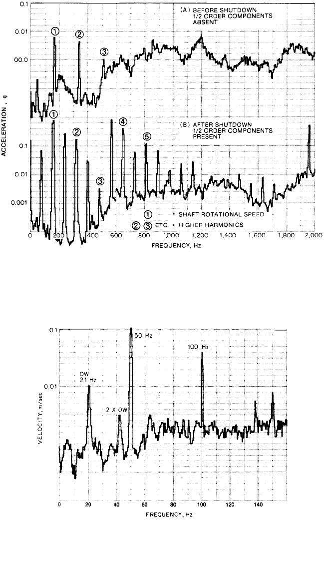
FIGURE 16.4 Spectrum analysis showing component due to oil whirl at 42
percent of the rotation speed measured on the journal bearing of a pump.
16.12
FIGURE 16.3 Acceleration spectra of a journal bearing on a centrifugal compressor. (A) Com-
pressor in good condition. Before shutdown, the vibration pattern is normal with few harmonics of
the compressor’s rotation speed and broadband noise at higher frequencies due to inherent turbu-
lences. (B) Compressor with looseness in the journal bearing. After shutdown, the higher-order har-
monics have an increased amplitude, and the presence of half-order harmonics can be observed.
8434_Harris_16_b.qxd 09/20/2001 12:16 PM Page 16.12