Harris C.M., Piersol A.G. Harris Shock and vibration handbook
Подождите немного. Документ загружается.

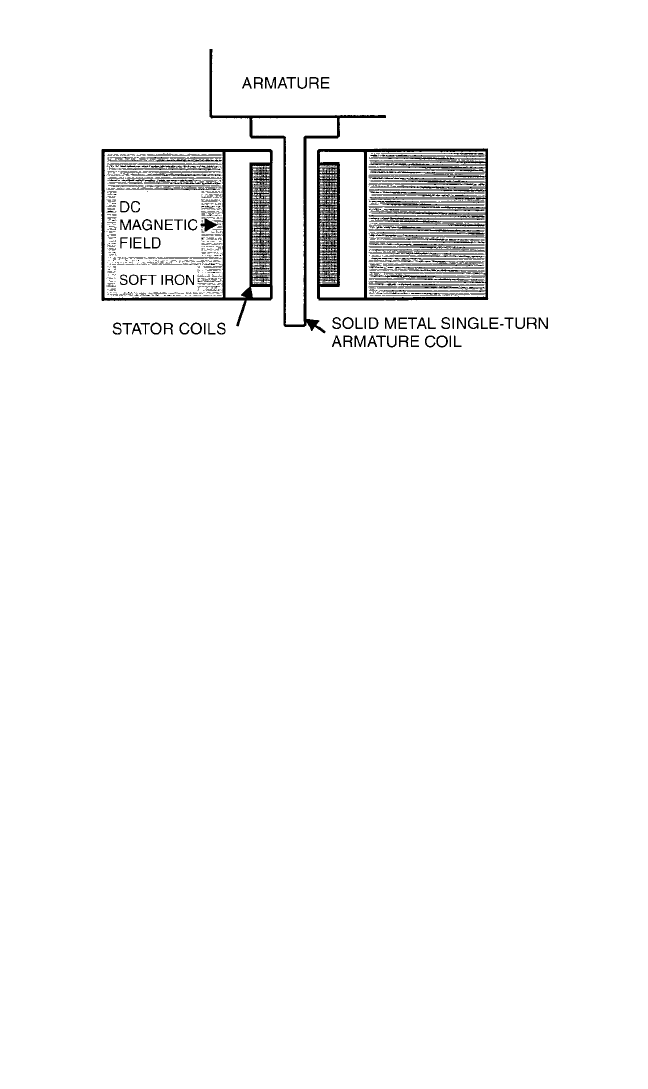
acts as the secondary in the transformer. The stator current inductively generates a
current in the single turn shorted armature coil. In Fig. 25.6, the dc magnetic field is
across the paper, the armature current is into the paper, and the generated force is
vertical. The advantages are a rugged armature design, and an armature that is elec-
trically isolated from the rest of the shaker.The disadvantages include a decrease in
performance at low frequencies due to inductive coupling losses and a slight prob-
lem cooling the armature. Because the induction losses are a function of scale, this
design is usually found in the larger electrodynamic shakers.
FREQUENCY RESPONSE CONSIDERATIONS
Testing procedures which call for sinusoidal motion (see Chap. 20) of a vibration-
machine table can be performed even though the frequency response curve of the
electrodynamic vibration machine is far from flat. For a test at a fixed frequency, the
driving voltage is adjusted until the table motion is equal in amplitude to that
required by the test specifications. If the procedure calls for cycling the frequency
between two frequency limits while keeping a constant displacement or acceleration,
a control system or servo control adjusts the driver-coil voltage as required to main-
tain the desired vibration machine table motion independent of the frequency of
operation. This control system provides a correction at any frequency of operation
within the testing frequency limits, but it can correct for only one operating frequency
at any instant of time. The closer the frequency response is to the desired variation in
acceleration with frequency, the smaller the corrections in driver-coil voltage will be
from the control system—thereby improving the attainable accuracy of the control.
Similarly for test procedures that call for a random vibration source, the auto-
spectrum of the source must be adjusted, because of test requirements and the fre-
quency response of the test system. A shaker with a more constant response will
allow for a greater range of spectral values than can be controlled.
Test procedures can also call for the reproduction of a transient. This test method
is called waveform control or waveform reproduction. For this test method, the fre-
quency response function between the power amplifier input voltage and the con-
trol accelerometer is measured with the test item in place. This information is used
VIBRATION TESTING MACHINES 25.9
FIGURE 25.6 Cross section in the vicinity of the armature of an
induction-type shaker.
8434_Harris_25_b.qxd 09/20/2001 11:56 AM Page 25.9

to construct an input voltage time-history that will reproduce the desired test time-
history at the control point.
In the past, analog control systems were used, but with the advent of relatively
inexpensive computers, digital control is now almost exclusively used. Digital vibra-
tion control systems are discussed in Chap. 27.
CHARACTERIZATION OF AN ELECTRODYNAMIC SHAKER AS A
TWO-PORT NETWORK
An electrodynamic shaker can be modeled as a mixed electrical/mechanical two-
port network
1,2
(see Chap. 10). This characterization can give good insight about the
performance capabilities of a shaker and/or a shaker/power supply combination. In
matrix form, this characterization can be written as
=
(25.1)
where E = the voltage required to drive the shaker
I = the current required to drive the shaker
A = the acceleration observed at the shaker/load interface
F = the force at the shaker/load interface
All the variables are complex functions of frequency as described in Chap. 22. The
terms in the impedance matrix are frequency response functions defined as
Z
11
=
F = 0
Z
12
=
I = 0
Z
21
=
F = 0
Z
22
=
I = 0
(25.2)
Two of the terms are easily measured. Z
11
is the unloaded table (no mechanical load
on the shaker) electrical impedance of the shaker, and Z
21
is the ratio of the
unloaded acceleration to input current of the shaker. Z
22
is the accelerance (ratio of
acceleration to force) looking into the shaker with the shaker electrical input open
(zero current, but with the field on). Z
12
is the ratio of voltage, generated at the open
electrical shaker input, to a driving force applied at the armature. The direct meas-
urement of Z
12
and Z
22
would require that an external force be applied to the shaker
and the resulting open circuit voltage and acceleration be measured, a difficult feat
in practice. But the terms in the impedance matrix can be measured experimentally
by performing experiments with two or more known loads attached to the shaker.
The general case is given by a system of equations for n measured load conditions,
where the subscripts indicate the different loading conditions.
=
(25.3)
Each test requires the measurement of the input voltage and current and the output
acceleration and force. If the test item is a rigid mass, the force can be estimated from
F = ma. In short hand, Eq. (25.3) will be written as
E = ZI (25.4)
I
n
F
n
...
...
I
2
F
2
I
1
F
1
Z
12
Z
22
Z
11
Z
21
E
n
A
n
...
...
E
2
A
2
E
1
A
1
A
F
A
I
E
F
E
I
I
F
Z
12
Z
22
Z
11
Z
21
E
A
25.10 CHAPTER TWENTY-FIVE
8434_Harris_25_b.qxd 09/20/2001 11:56 AM Page 25.10

The impedance matrix can then be found using a Moore-Penrose pseudoinverse
3
Z = EI
−1
(25.5)
If the number of test conditions is greater than two, the solution is in a least-squares
sense. This assumes the inverse exists. The equation is typically solved at a finite set
of discrete frequencies using techniques described in Chap. 22. Other forms of the
impedance matrix can be defined which give frequency response functions that may
be more useful in a particular application. The admittance matrix is defined as
=
(25.6)
The transmission matrix is defined as
=
(25.7)
The reciprocal transmission matrix is defined as
=
(25.8)
These matrices are all related by the equations
Y = Z
−1
R = T
−1
T =
(25.9)
R =
For example, for a sine test, the voltage and current required for a particular load
acceleration are easily determined by substituting
F = Z
m
A (25.10)
into Eq. (25.7) to give
= A
(25.11)
Z
m
is the driving point (the interface at the shaker) free effective mass
4
(the ratio of
force to acceleration) of the load (test item and fixtures). The free effective mass is
related to the mechanical impedance, Z (the ratio of force to velocity), defined in
Chap. 10, by the relationship, Z
m
= jωZ. In general, Z
m
is a frequency response func-
tion. If the load and fixtures are a rigid mass, Z
m
is a constant equal to the mass of the
test item and fixtures.
Similarly, for a given shaker power supply with known characteristics (the maxi-
mum output voltage and current capability), the shaker performance capabilities
(the achievable acceleration) for a given load are easily determined from Eq.
1
Z
m
T
12
T
22
T
11
T
21
E
I
Z
12
Z
21
− Z
11
Z
22
−Z
11
Z
22
1
1
Z
12
Z
12
Z
21
− Z
11
Z
22
−Z
22
Z
11
1
1
Z
21
E
I
R
12
R
22
R
11
R
21
A
F
A
F
T
12
T
22
T
11
T
21
E
I
E
A
Y
12
Y
22
Y
11
Y
21
I
F
VIBRATION TESTING MACHINES 25.11
8434_Harris_25_b.qxd 09/20/2001 11:56 AM Page 25.11

(25.11). The maximum acceleration that can be achieved for a given voltage limit is
A
Elim
= |E
lim
/(T
11
+ T
12
Z
m
)|
The maximum acceleration that can be achieved for a given current limit is
A
Ilim
= |I
lim
/(T
21
+ T
22
Z
m
)|
The maximum acceleration that can be reached before either limit is reached is the
smaller of these two numbers.
A
max
= min(A
Elim
, A
Ilim
)
The development is easily generalized for random and transient testing using the
techniques in Chap. 22.The development can be generalized for the multiple shaker
system driving a single test item.
5
A useful review of electrodynamic shakers is given in Ref. 6.
SYSTEM RATINGS
The electrodynamic vibration machine system is rated: (1) in terms of the peak value
of the sinusoidal generated force for sinusoidal vibration testing and (2) in terms of
the rms and instantaneous values of the maximum force generated under random
vibration testing. In order to determine the acceleration rating of the system with a
test load on the vibration table, the weight of the test load, assumed to be effective
at all frequencies, must be known and used in the following expressions:
=
(25.12)
rms
=
where = a/g, a dimensionless number expressing the ratio of the peak sinu-
soidal acceleration to the acceleration due to gravity (i.e., the peak
sinuosidal acceleration in g’s)
rms
= a
rms
/g, a number expressing the ratio of the rms value of random
acceleration to the acceleration due to gravity
W
L
= weight of load
W
T
= equivalent weight of table driver-coil assembly and associated mov-
ing parts
F = rated peak value of sinusoidal generated force
F
rms
= rated rms value of random generated force
The force rating of an electrodynamic vibration machine is the value of force
which can be used to calculate attainable accelerations for any rigid-mass table load
equal to (or greater than) the driver coil weight. It is not necessarily the force gener-
ated by the driver coil. These two forces are identical only if the operating frequen-
F
rms
W
L
+ W
T
F
W
L
+ W
T
25.12 CHAPTER TWENTY-FIVE
8434_Harris_25_b.qxd 09/20/2001 11:56 AM Page 25.12

cies are sufficiently below the axial resonance frequency of the armature assembly,
where it acts as a rigid body. As the axial resonance frequency is approached, a
mechanical magnification of the force generated electrically by the driver coil results.
The design of the driving power supply takes into account the possible reduction in
driver-coil current at frequencies approaching the armature axial resonance fre-
quency, since full current in this range cannot be used without exceeding the rated
value of transmitted force at the table, possibly causing structural damage.
In those cases where the test load dissipates energy mechanically, the system per-
formance should be analyzed for each specific load since normal ratings are based
on a dead-mass, nondissipative type of load. This consideration is particularly signif-
icant in resonance-type fatigue tests at high stress levels.
PROMINENT FEATURES
●
A wide range of operating frequencies is possible, with a properly selected electric
power source, from 0 to above 30,000 Hz. Small, special-purpose machines have
been made with the first axial/resonance mode above 26,000 Hz, giving inherently
a resonance-free, flat response to 10,000 Hz.
●
Frequency and displacement amplitude are easily controlled by adjusting the
power-supply frequency and voltage.
●
Pure sinusoidal table motion can be generated at all frequencies and amplitudes.
Inherently, the table acceleration is the result of a generated force proportional to
the driving current. If the electric power supply generates pure sinusoidal voltages
and currents, the waveform of the acceleration of the table will be sinusoidal, and
background noise will not be present. Operation with table acceleration wave-
form distortion of less than 10 percent through a displacement range of 10,000-to-
1 is common, even in the largest machines. Velocity and displacement waveforms
obtained by the single and double integration of acceleration, respectively, will
have even less distortion.
●
Random vibration, as well as sinusoidal vibration, or a combination of both, can
be generated by supplying an appropriate input voltage.
●
A unit occupying a small volume, and powered from a remote source, can be used
to generate small vibratory forces.A properly designed unit adds little mass at the
point of attachment and can have high mobility without mechanical damping.
●
Leakage magnetic flux is present around the main magnet circuit. This leakage
flux can be minimized by proper design and the use of degaussing coil techniques.
SPECIFICATIONS
Design Factors
Force Output. The maximum vector-force output for sinusoidal excitation shall
be given for continuous duty and may additionally be given for intermittent duty.
When nonsinusoidal motions are involved, the force may additionally be given in
terms of an rms value together with a maximum instantaneous value. The latter
value is especially significant when a random type of excitation is required.
In some cases of wide-frequency-band operation of the electrodynamic vibration
machine, the upper frequencies are sufficiently near the axial mechanical resonance
frequency of the coil-table assembly to provide some amplification of the generated
VIBRATION TESTING MACHINES 25.13
8434_Harris_25_b.qxd 09/20/2001 11:56 AM Page 25.13

force. Most system designs account for this magnification, when present, by reducing
the capacity of the electrical driving power accordingly.
The peak values of the input electrical signal, for random excitation, may extend
to indefinitely large values. In order that the armature coil voltage and generated
force may be limited to reasonable values, the peak values of the excitation are
clipped so that no maxima shall exceed a given multiple of the rms value. The mag-
nitude of the maximum clipped output shall be specified preferably as a multiple of
the rms value. If adjustments are possible, the range of magnitudes shall be given.
Weight of Vibrating Assembly. The weight of the vibration coil-table assembly
shall be given. It shall include all parts which move with the table and an appropri-
ate percentage of the weight of those parts connecting the moving and stationary
parts giving an effective over-all weight.
Vibration Direction. The directions of vibration shall be specified with respect
to the surface of the vibration table and with respect to the horizontal or vertical
direction. Provisions for changing the direction of vibration shall be stated.
Unsupported Load. The maximum allowable weight of a load not requiring
external supports shall be given for horizontal and vertical orientations of the vibra-
tion table. This load in no way relates to dyanmic performance but is a design limi-
tation, the basis of which may be stated by the manufacturer.
Static Moments and Torques. Static moments and torques may be applied to
the coil-table assembly of a vibration machine by the tightening of bolts and by the
overhang of the center-of-gravity of an unsupported load during horizontal vibra-
tion. The maximum permissible values of these moments and torques shall be spec-
ified. These loads in no way relate to the dynamic performance but are design
limitations, the basis for which may be stated by the manufacturer.
Total Excursion Limit. The maximum table motion between mechanical stops
shall be given together with the maximum vibrational excursion permissible with no
load and with maximum load supportable by the table.
Acceleration Limit. The maximum allowable table acceleration shall be given.
(These large maxima may be involved in the drive of resonant systems.)
Stiffness of Coil-Table Assembly Suspension System
AXIAL STIFFNESS: The stiffness of the suspension system for axial deflections of
the coil-table assembly shall be given in terms of pounds per inch of deflection. The
natural frequency of the unloaded vibrating assembly may also be given. Provisions,
if any, to adjust the table position to compensate for position changes caused by dif-
ferent loads shall be described.
SUSPENSION RESONANCES: Resonances of the suspension system should be
described together with means for their adjustment where applicable.
Axial Coil-Table Resonance. The resonance frequency of the lowest axial
mode of vibration of the coil-table assembly shall be given for no load and for an
added dead-weight load equal to 1 and to 3 times the coil-table assembly weight. If
this resonance frequency is not obvious from measurements of the table amplitude
vs. frequency, it may be taken to be approximately equal to the lowest frequency,
above the rigid-body resonance of the table-coil assembly on its suspension system,
at which the phase difference between the armature coil current and the accelera-
tion of the center of the table is 90°.
Impedance Characteristics. When an exciter or vibration machine is consid-
ered independent of its power supply, information concerning the electrical imped-
ance characteristics of the machine shall be given in sufficient detail to permit
matching of the power-supply output to the vibration-machine input. It is suggested
that consideration be given to providing schematic circuit diagrams (electrical and
25.14 CHAPTER TWENTY-FIVE
8434_Harris_25_b.qxd 09/20/2001 11:56 AM Page 25.14

mechanical or equivalent electrical) together with corresponding equations that
contain the principal features of the machine.
Environmental Extremes. When it is anticipated that the vibration machine
will be used under conditions of abnormal pressure and temperature, the following
information shall be supplied as may be applicable: maximum simulated altitude (or
minimum pressure) under which full performance ratings can be applied; maximum
simulated altitude under which reduced performance ratings can be applied; maxi-
mum ambient temperature for rated output; low-temperature limitations; humidity
limitations.
Performance. The performance relates in part to the combined operation of the
vibration generator and its power supply.
Amplitude-Frequency Relations. Data on sinusoidal operation shall be given as
a series of curves for several table loads, including zero load, and for a load at least 3
times the weight of the coil-table assembly. Maximum loads corresponding to 20g and
10g table acceleration under full-rated force output would be preferred. These curves
should give amplitudes of table displacement, velocity, or acceleration, whichever is
limiting, throughout the complete range of operating frequencies corresponding to
maximum continuous ratings of the system. Additionally, the maximum rated force
should be given. If this force is frequency-dependent, it should be presented as a curve
with the ordinate representing the force and the abscissa the frequency.
If the system is for broad-band use, necessarily employing an electronic power
amplifier, the exciting voltage signal applied to the input of the system shall be held
constant and the output acceleration shall be plotted as a function of frequency with
and without filters or other compensating devices for the loads and accelerations
indicated above. If the vibrator is used only for sinusoidal vibrations, and employs
servo amplitude control, the curves should be obtained under automatic frequency
sweeping conditions with the control system included.
Waveform. Total rms distortion of the acceleration waveform at the center of
the vibration table, or at the center on top of the added test weight, shall be fur-
nished to show at least the frequencies of worst waveform under the test conditions
specified under the above paragraph.The pickup type, and frequency range, shall be
given together with the frequency range of associated equipment. It is desirable to
have the over-all frequency range at least 10 times the frequency of the fundamental
being recorded. Tabular data on harmonic analysis may alternatively or additionally
be given.
Magnetic Fields. The maximum values of constant and alternating magnetic
fields, due to the vibration exciter, in the region over the surface of the vibration
table should be indicated. If degaussing coils are furnished, these values should be
given with and without the use of the degaussing coils.
Frequency Range. The over-all frequency range shall be given. A group of fre-
quency ranges shall also be given for electronic power supplies if they require
changes of their output impedance for the different ranges.
Frequency Drift. The probable drift of a set frequency shall be stated, together
with factors that contribute to the drift. This shall apply for nonresonant loads.
Signal Generator. A vibration pickup, if built into the vibration machine, shall
have calibrations furnished over a specified frequency and amplitude range.
Installation Requirements. Recommendations shall be given as to suitable
methods for installing the vibration machine and auxiliary equipment. Electrical and
other miscellaneous requirements shall be stated.
VIBRATION TESTING MACHINES 25.15
8434_Harris_25_b.qxd 09/20/2001 11:56 AM Page 25.15
HYDRAULIC VIBRATION MACHINE
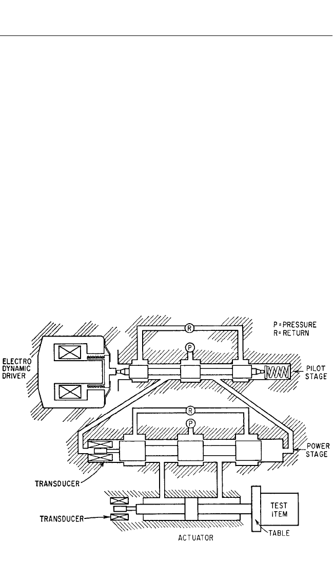
The hydraulic vibration machine is a device which transforms power in the form of a
high-pressure flow of fluid from a pump to a reciprocating motion of the table of the
vibration machine.A schematic diagram of a typical machine is shown in Fig. 25.7. In
this example, a two-stage electrohydraulic valve is used to deliver high-pressure
fluid, first to one side of the piston in the actuator and then to the other side, forcing
the actuator to move with a reciprocating motion. This valve consists of a pilot stage
and power stage, the former being driven with a reciprocating motion by the elec-
trodynamic driver. At the time the actuator moves under the force of high-pressure
fluid on one side of the piston, the fluid on the other side of the piston is forced back
through the valve at reduced pressure and is returned to the pump.
The electrohydraulic valve is usually mounted directly on the side of the actuator
cylinder, forming a close-coupled assembly of massive steel parts. The close proxim-
ity of the valve and cylinder is desirable to reduce the volume and length of the con-
necting fluid paths between the several spools and the actuator, thereby minimizing
the effects of the compliance of the fluid and the friction to its flow. Many types of
electrohydraulic valves exist, all of which fail to meet the requirement of sufficient
flow at high frequencies to give vibration machine performance equivalent to exist-
ing electrodynamic machine performance at 2000 Hz.
OPERATING PRINCIPLE
In Fig. 25.7, the pilot and power spools of a hydraulic vibration machine are shown in
the “middle” or “balanced” position, blocking both the pump high-pressure flow P and
25.16 CHAPTER TWENTY-FIVE
FIGURE 25.7 Schematic diagram of a typical hydraulic vibration machine.
8434_Harris_25_b.qxd 09/20/2001 11:56 AM Page 25.16
the return low-pressure flow R. Correspondingly, the piston of the actuator must be
stationary since there can be no fluid flow either to or from the actuator cylinder. If the
pilot spool is displaced to the right of center by a force from the electrodynamic driver,
then high-pressure fluid P will flow through the passage from the pilot spool to the left
end of the power spool, causing it to move to the right also.This movement forces the
trapped fluid from the right-hand end of the power spool through the connecting pas-
sage, back to the pilot stage, and then through the opening caused by the displacement
of the pilot spool to the right, to the chamber R connected to the return to the pump.
Correspondingly, if the pilot spool moves to the left, the flow to and from the power
spool is reversed, causing it to move to the left. For a given displacement of the pilot
spool, a flow results which causes a corresponding velocity of the power spool. A dis-
placement of the power spool to the right allows the flow of high-pressure fluid P from
the pump to the left side of the piston in the actuator, causing it to move to the right
and forcing the trapped fluid on the right of the piston to be expelled through the con-
necting passage to the power spool and out past the right-hand restrictions to the
return fluid chamber R. The transducers shown on the power spool and the actuator
shaft are of the differential transformer type and are used in the feedback circuit to
improve system operation and provide electrical control of the average (i.e., station-
ary) position of the actuator shaft relative to the actuator cylinder.
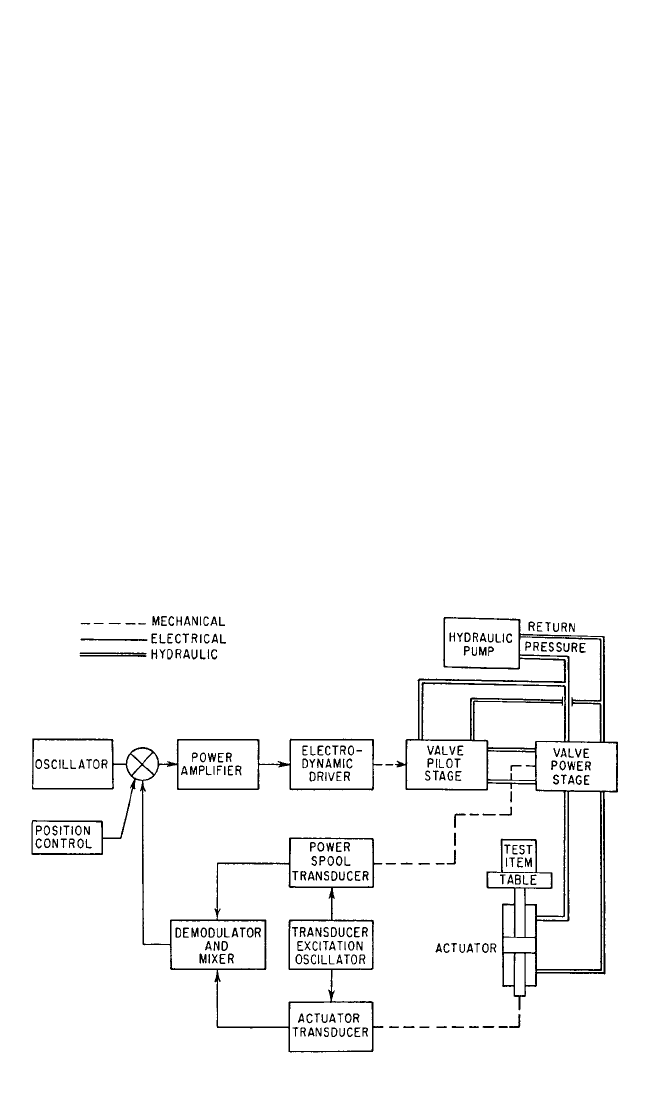
A block diagram of the complete hydraulic vibration machine system is shown in
Fig. 25.8. The pump, in conjunction with accumulators in the pressure and return
lines at the hydraulic valve, should be capable of variable flow while maintaining a
fixed pressure. Most systems to date have required an operating pump pressure of
3000 lb/in.
2
(20 MPa). The upper limit of efficiency of the hydraulic valve is approx-
imately 60 percent, the losses being dissipated in the form of heat. Mechanical loads
are seldom capable of dissipating appreciable power; most of the power in the pump
VIBRATION TESTING MACHINES 25.17
FIGURE 25.8 Block diagram—hydraulic vibration machine system.
8434_Harris_25_b.qxd 09/20/2001 11:56 AM Page 25.17

discharge is converted to a temperature rise in the fluid.Therefore a heat exchanger
limiting the fluid temperature must be included as part of the system.
PROMINENT FEATURES
●
Large generated forces or large strokes can be provided relatively easily. Large
forces and large velocities of motion, made possible with a large stroke, determine
the power capacity of the system. For example, one hydraulic vibration machine
has a peak output power of 450,000 lb-in./sec (approximately 34 hp or 25 kW)
with a single electrohydraulic valve. This power can be increased by the installa-
tion of several valves on a single actuator.Appreciable increases in valve flow can
be realized by sacrificing high-frequency performance. Hence, the hydraulic vibra-
tion machine excels at low frequencies where large force, stroke, and power capac-
ity are required.
●
The hydraulic machine is small in weight, relative to the forces attainable; there-
fore, a rigid connection to firm ground or a large massive base is necessary to
anchor the machine in place and to attenuate the vibration transmitted to the sur-
rounding area.
●
The main power source is hydraulic, which is essentially dc in character from
available pumps. The electrical driving power for controlling the valve is small.
Therefore, the operating frequency range can be extended down to zero Hz.
●
The magnetic leakage flux in the region of the table is insignificant by comparison
with the electrodynamic-type vibration machine.
●
The machine, with little modification, is suitable for use in high- and low-
temperature, humidity, and altitude environments.
●
The machine is inherently nonlinear with amplitude in terms of electrical input
and output flow or velocity.
PIEZOELECTRIC VIBRATION EXCITERS
A piezoelectric material (see Chap. 12) can be used to generate motion and act as a
piezoelectric vibration exciter. Typically a piezoelectric exciter employs a number of
disks of piezoelectric material as illustrated in Fig. 25.9; this arrangement increases
the ratio of the displacement output to voltage input sensitivity of the exciter. The
strain is proportional to the charge, and the charge is increased by increasing the
voltage gradients across the piezoelectric material.The voltage gradient is increased
by using many thin layers of piezoelectric material, separated with a conducting
material, with alternating polarity on the conducting separators.This arrangement of
alternating layers of piezoelectric material and conducting material is called a piezo-
electric stack. Because the piezoelectric stack has little tensile strength, the stack
must be preloaded. The stiffness of the preloading mechanism must be much less
than the stiffness of the piezoelectric stack so that preloading will not influence the
mechanical output significantly. The combination of the piezoelectric stack (acting
like a displacement actuator) and a reaction mass forms a reaction-type vibration
exciter as described above. The reaction mass of the piezoelectric exciter can be the
armature mass of a small electrodynamic exciter. This effectively places an electro-
dynamic and a piezoelectric exciter in series, producing a machine with a usable out-
put over a wide frequency range.
25.18 CHAPTER TWENTY-FIVE
8434_Harris_25_b.qxd 09/20/2001 11:56 AM Page 25.18