Harris C.M., Piersol A.G. Harris Shock and vibration handbook
Подождите немного. Документ загружается.

PROMINENT FEATURES
●
The exciters can have a usable frequency range from 0 to 60 kHz.
●
The low-frequency output is severely limited by the displacement limits of the
piezoelectric stack, usually a few thousandths of an inch (a few hundredths of a
millimeter).
●
The high-frequency output is limited by internal resonances of the vibration exciter.
●
The force output of the exciter is limited by the displacement limit of the piezo-
electric stack and by the mass of the reaction mass.
●
The power supply for a piezoelectric exciter requires high voltages (typically
about 1000 volts) and sufficient current to drive the capacitance (typically 10 to
1000 nanofarads) of the device.
IMPACT EXCITERS
A limited amount of vibration testing, such as some modal testing and some stress
screening, require a broad frequency bandwidth of relatively uncontrolled vibra-
tion. A class of exciters broadly known as impact exciters (and also called repetitive
shock machines) is sometimes used for the above applications. These devices
depend on the property that a short impact generates a broad bandwidth of vibra-
tion energy. Each impact is a short transient, for example see Fig. 26.1, but repeated
VIBRATION TESTING MACHINES 25.19
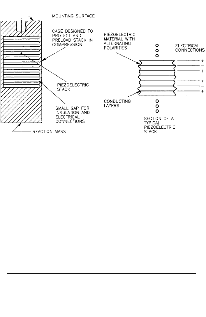
FIGURE 25.9 Simplified cross section of a piezoelectric vibration exciter. A compressed piezo-
electric stack is excited with an oscillating voltage. An electrical voltage applied to the electrical con-
nections causes the piezoelectric stack to elongate and contract, producing a relative displacement
between the mounting surface and the reaction mass. The inertia of the reaction mass results in a
force being applied to an item mounted on the mounting surface.
8434_Harris_25_b.qxd 09/20/2001 11:56 AM Page 25.19

impacts result in a quasi-steady-state vibration having a wide frequency bandwidth.
If the impacts are periodic, the spectrum is composed of the fundamental frequency
of the impacts and many harmonics of this fundamental frequency, i.e., the excita-
tion is essentially a periodic function. However, the impacts are often varied ran-
domly in magnitude and spacing to produce a time-averaged spectrum that is
smoother, much like random vibration. Nevertheless, the instantaneous spectrum
or Wigner distribution (see Chap. 22) for the excitation will still reveal an instanta-
neous periodic function with a time-varying magnitude and fundamental fre-
quency. The probability distribution can vary significantly from a Gaussian
distribution. The vibration characteristics are strongly influenced by the dynamics
of the structure on which they are mounted. The impact exciters can be mounted
directly to the test specimen, or the exciters can excite a table on which the test item
is mounted. The latter can be classed as a vibration testing machine.
PROMINENT FEATURES
●
The design is usually simple, compact, and rugged.
●
The maximum attainable displacement is usually small.
●
The vibration is relatively uncontrolled. The user has little control over the spec-
trum of the resulting vibration.
MULTIPLE SHAKERS DRIVING
A SINGLE TEST ITEM
It is sometimes desirable to have more than one shaker driving a test item. Some of
the reasons include:
Desire to excite many modes. This is the motivation for multiple input modal
tests. A single input may not be capable of exciting all the modes, but multiple
input tests have a better chance.
Desire to provide more representative boundary conditions. Many test items are
not mounted in service on rigid foundations. Single-axis testing on rigid fixtures
is often a poor simulation of the boundary conditions of service environments.
Multiple input tests can sometimes provide more realistic boundary conditions.
The vibration input in the field environment is often not through a single point.
Large test items. Large test items are difficult to drive with a single shaker.
Examples include complete airplanes or space launch systems, seismic simula-
tions, automobiles, and other large transportation systems. The size and/or force
requirements to test these items are often beyond the capabilities of a single
shaker.
Desire to provide excitation in more than one direction. Most conventional
shakers excite the test item in one rectilinear direction. Most environments
include vibration in several directions (both rectilinear and rotation) simultane-
ously. In an effort to provide more realistic testing, shaker systems with inputs in
several directions at the same time are desirable.
Multiple exciters driving a single test item have been used extensively in modal
testing (see Chap. 21). This is relatively easy because control of the vibration input
is not usually necessary. Multiple input tests with controlled inputs are more diffi-
25.20 CHAPTER TWENTY-FIVE
8434_Harris_25_b.qxd 09/20/2001 11:56 AM Page 25.20

cult because of cross-coupling effects. Cross-coupling is where the input at one
point causes response at the control point of another input. Control of systems
with cross-coupling requires a careful mechanical design and a carefully designed
control system (see Chap. 27). The shaker, the fixture, and the control system form
three legs of a triad. They must all work together; a weakness in any of the three
can result in the system failure. The mechanical design must minimize cross-
coupling effects and the control system must compensate for the remaining cross-
coupling.
Systems with two inputs typically controlling one translation and one rotation
degree of freedom are not very difficult to design. An example would be a horizon-
tal beam-like structure with the vertical translation controlled independently at each
end. Isolation of the rotation from the shakers can usually be accomplished with fix-
tures that are stiff axially but soft in bending.
The mechanical design of systems with more than two degrees of freedom is
more difficult. The shaker providing the input can usually move in only one direc-
tion. If the test item is to move in more than one direction and/or rotate, the mechan-
ical design of the system must isolate all the motion except in one direction from the
shakers. It is also difficult to restrain other degrees-of-freedom, for example, rota-
tions. Restraint of unwanted motion is usually accomplished with passive restraints
(for example, hydrostatic bearings) or with active restraints using the exciters and
the control system. Undesired motion, compromising the test, will result if the
uncontrolled degrees of freedom are not restrained.
A system using three electrodynamic shakers controlling three orthogonal
translations, with the three rotations passively restrained, has been built.
7
This sys-
tem has a usable bandwidth of almost 2 kHz. Electrodynamic systems with six
degrees-of-freedom have also been built with varying degrees of success. Electro-
hydraulic shaker systems with six rigid-body degrees-of-freedom (three transla-
tions and three rotations) have been built.
8
These systems have a usable
bandwidth of about 500 Hz. Larger electrohydraulic systems with two to six
degrees-of-freedom have been built for seismic simulation with a bandwidth of
about 50 Hz (see Chap. 24). Other electrohydraulic systems with as many as 18
hydraulic actuators with a bandwidth of about 50 Hz are used as road simulators
in the automotive industry. One of these systems is illustrated in Fig. 25.10. An
advantage of electrohydraulic shakers for multiple input applications is that their
mechanical input impedance is relatively high, reducing the cross-coupling effects.
Their disadvantage is that they are all inherently nonlinear, which makes control
more difficult. All of these systems, both electrodynamic and electrohydraulic, are
capable, with appropriate control systems, of performing sine, random, and tran-
sient tests.
VIBRATION FIXTURES
Test items are usually attached to a shaker with a fixture. Seldom will the test item
mount directly on the shaker. These fixtures are usually designed to be rigid in the
frequency band of interest and lightweight. Rigidity is required because the vibra-
tion test is typically controlled at a single point.The assumption is that the motion of
the control point is representative of the input to the test item. If the fixture is not
rigid, this assumption is obviously not true. Also, flexible fixtures typically have one
or more frequencies where the operating shape at the control point is near zero.This
will result in large, unrealistic responses of the test item. The fixtures need to be
VIBRATION TESTING MACHINES 25.21
8434_Harris_25_b.qxd 09/20/2001 11:56 AM Page 25.21
lightweight to maximize the force available to drive the test item. Light weight and
rigidity are contradictory requirements. Design of satisfactory vibration fixtures is a
combination of experience, analysis, and compromise. Vibration fixtures are dis-
cussed in Chap. 20.
REFERENCES
1. Baher, H.: “Synthesis of Electrical Networks,” John Wiley & Sons, Inc., New York, 1984.
2. Weinberg, L.: “Network Analysis and Synthesis,” McGraw-Hill Book Company, Inc., New
York, 1962.
3. Golub, G. H., and C. F. Van Loan: “Matrix Computations,” 2d ed., Johns Hopkins University
Press, Baltimore, Md., 1989.
4. “Vibration and Shock—Experimental Determination of Mechanical Mobility. Part 1: Basic
Definitions and Transducers,” ISO 7626-1, 1986.
5. Smallwood, D. O.: J. of the Institute of Environmental Sciences, 60(5):27 (1997).
6. Lang, G. F.: Sound and Vibration, 31(4):14 (1997).
7. Stroud, R. C., and G. A. Hamma: Sound and Vibration, 22(4):18 (1988).
8. Hamma, G. A., R. C. Stroud, M. A. Underwood, W. B. Woyski, R. C. Tauscher, and K. L. Cap-
pel: Sound and Vibration, 30(4):20 (1996).
25.22 CHAPTER TWENTY-FIVE
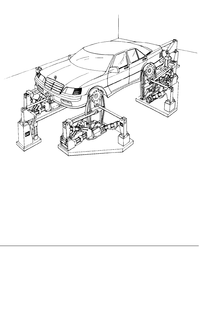
FIGURE 25.10 A road simulator which uses a cross-coupled multiple-drive/multiple-control-point
predetermined waveform control system. The predetermined waveforms (with a bandwidth of about 1
to 50 Hz) are measured on the vehicle while driving on a road. The predetermined waveforms are
reproduced on the vehicle during the simulation on the road simulator. Four hydraulic actuators drive
each wheel hub, and two hydraulic actuators drive the vehicle fore and aft at the bumpers. (MTS Corp.)
8434_Harris_25_b.qxd 09/20/2001 11:56 AM Page 25.22

CHAPTER 26, PART I
SHOCK TESTING
MACHINES
Richard H. Chalmers
INTRODUCTION
Equipment must be sufficiently rugged to operate satisfactorily in the shock and vibra-
tion environments to which it will be exposed and to survive transportation to the site
of ultimate use. To ensure that the equipment is sufficiently rugged and to determine
what its mechanical faults are, it is subjected to controlled mechanical shocks on shock
testing machines. Mechanical shock is a nonperiodic excitation (e.g., a motion of the
foundation or an applied force) of a mechanical system that is characterized by sud-
denness and severity, and it usually causes significant relative displacements in the sys-
tem. The severity and nature of the applied shocks are usually intended to simulate
environments expected in later use or to be similar to important components of those
environments. However, a principal characteristic of shocks encountered in the field is
their variety.These field shocks cannot be defined exactly. Therefore shock simulation
can never exactly duplicate shock conditions that occur in the field.
There is no general requirement that a shock testing machine reproduce field
conditions.All that is required is that the shock testing machine provide a shock test
such that equipment which survives is acceptable under service conditions. Assur-
ance that this condition exists requires a comparison of shock test results and field
experience extending over long periods of time. This comparison is not possible for
newly developed items. It is generally accepted that shocks that occur in field envi-
ronments should be measured and that shock machines should simulate the impor-
tant characteristics of shocks that occur in field environments or have a damage
potential which by analysis is shown to be similar to that of a composite field shock
environment against which protection is required.
A shock testing machine (frequently called a shock machine) is a mechanical
device that applies a mechanical shock to an equipment under test.The nature of the
shock is determined from an analysis of the field environment. Tests by means of
shock machines usually are preferable to tests under actual field conditions for four
principal reasons:
1. The nature of the shock is under good control, and the shock can be repeated
with reasonable exactness. This permits a comparative evaluation of the equip-
ment under test and allows exact performance specifications to be written.
2. The intensity and nature of shock motions can be produced that represent an
average condition for which protection is practical, whereas a field test may
involve only a specific condition that is contained in this average.
26.1
8434_Harris_26_b.qxd 09/20/2001 11:54 AM Page 26.1

3. The shock machine can be housed at a convenient location with suitable facilities
available for monitoring the test.
4. The shock machine is relatively inexpensive to operate, so it is practical to per-
form a great number of developmental tests on components and subassemblies in
a manner not otherwise practical.
SHOCK-MACHINE CHARACTERISTICS
DAMAGE POTENTIAL AND SHOCK RESPONSE SPECTRA
The damage potential of a shock motion is dependent upon the nature of an equip-
ment subjected to the shock, as well as upon the nature and intensity of the shock
motion.To describe the damage potential, a description of what the shock does to an
equipment must be given—a description of the shock motion is not sufficient. To
obtain a comparative measure of the damage potential of a shock motion, it is cus-
tomary to determine the effect of the motion on simple mechanical systems. This
is done by determining the maximum responses of a series of single degree-of-
freedom systems (see Chap. 2) to the shock motion and considering the magnitude
of the response of each of these systems as indicative of the damage potential of the
shock motion. The responses are plotted as a function of these natural frequencies.
A curve representing these responses is called a shock response spectrum, or
response spectrum (see Chap. 23). Its magnitude at any given frequency is a quanti-
tative measure of the damage potential of a particular shock motion to a single
degree-of-freedom system with that natural frequency. This concept of the shock
response spectrum originally was applied only to undamped single degree-of-
freedom systems, but the concept has been extended to include systems in which any
specified amount of damping exists.
The response of a simple system can be expressed in terms of the relative dis-
placement, velocity, or acceleration of the system. It is customary to define velocity
and acceleration responses as 2πf and (2πf )
2
times the maximum relative displace-
ment response, where f is frequency expressed in hertz. The corresponding response
curves are called displacement, velocity, or acceleration shock response spectra. A
more detailed discussion of shock response spectra is given in Chap. 23.
Of the three motion parameters (displacement, velocity, and acceleration)
describing a shock spectrum, velocity is the parameter of greatest interest from the
viewpoint of damage potential. This is because the maximum stresses in a structure
subjected to a dynamic load typically are due to the responses of the normal modes
of the structure, that is, the responses at natural frequencies (see Chap. 21). At any
given natural frequency, stress is proportional to the modal (relative) response
velocity.
1
Specifically,
σ
max
= Cν
max
Eρ
(26.1)
where σ
max
= maximum modal stress in the structure
ν
max
= maximum modal velocity of the structural response
E = Young’s modulus of the structural material
ρ=mass density of the structural material
C = constant of proportionality dependent upon the geometry of the
structure (often assumed for complex equipment to be 4 < C < 8)
2
26.2 CHAPTER TWENTY-SIX, PART I
8434_Harris_26_b.qxd 09/20/2001 11:54 AM Page 26.2

Of course, if the shock response spectrum for a test machine–generated shock is com-
puted solely to validate that test results comply with a specified shock response spec-
trum, or for comparison to the shock response spectra computed from measured
shocks in a service environment, then either displacement or acceleration shock
response spectra are as meaningful as a velocity shock response spectrum. However,
if the maximum stress in the structure subjected to the shock is of primary interest,
the velocity shock response spectrum is the most applicable.
MODIFICATION OF CHARACTERISTICS
BY REACTIONS OF TEST ITEM
The shock motion produced by a shock machine may depend upon the mass and fre-
quency characteristics of the item under test. However, if the effective weight of the
item is small compared with the weight of the moving parts of the shock machine, its
influence is relatively unimportant. Generally, however, the reaction of the test item
on the shock machine is appreciable and it is not possible to specify the test in terms
of the shock motions unless large tolerances are permissible. The test item acts like
a dynamic vibration absorber (see Chap. 6). If the item is relatively heavy, this causes
the shock response spectra of the exciting shock to have minima at the frequencies
of the test item; it also causes its mounting foundation to have these minima during
shock excitation at field installations. Shock tests and design factors are sometimes
established on the basis of an envelope of the maximum values of shock response
spectra. However, maximum stresses in the test item will most probably occur at the
antiresonance frequencies where the shock response spectrum exhibits minimum
values. To require that the item withstand the upper limit of spectra at these fre-
quencies may result in overtesting and overdesign. Considerable judgment is there-
fore required both in the specification of shock tests and in the establishment of
theoretical design factors on the basis of field measurements. See Chap. 20 for a
more complete discussion of this subject.
DOMINANT FREQUENCIES OF SHOCK MACHINES
The shock motion produced by a shock machine may exhibit frequencies that are char-
acteristic of the machine. These frequencies may be affected by the equipment under
test.The probability that these particular frequencies will occur in the field is no greater
than the probability of other frequencies in the general range of interest. A shock test,
therefore, discriminates against equipment having elements whose natural frequencies
coincide with frequencies introduced by the shock machine. This may cause failures to
occur in relatively good equipment whereas other equipment, having different natural
frequencies, may pass the test even though of poorer quality. Because of these factors,
there is an increasing tendency to design shock machines to be as rigid as possible, so
that their natural frequencies are above the range of frequencies that might be strongly
excited in the equipment under test. The shock motion is then designed to be the sim-
plest shape pulse that will give a desired shock motion or response spectrum.
CALIBRATION
A shock-machine calibration is a determination of the shock motions or response
spectra generated by the machine under standard specified conditions of load,
mounting arrangements, methods of measurement, and machine operation. The
SHOCK TESTING MACHINES 26.3
8434_Harris_26_b.qxd 09/20/2001 11:54 AM Page 26.3

purpose of the calibration is not to present a complete study of the characteristics of
the machine but rather to present a sufficient measure of its performance to ensure
the user that the machine is in a satisfactory condition. Measurements should there-
fore be made under a limited number of significant conditions that can be accurately
specified and easily duplicated. Calibrations are usually performed with deadweight
loads rigidly attached to the shock machine.
The statement of calibration results must include information relative to all fac-
tors that may affect the nature of the motion.These include the magnitude, dimen-
sions, and type of load; the location and method of mounting of the load;
factors related to the operation of the shock machine; the locations and mounting
arrangements of pickups; and the frequency range over which the measurements
extend.
SPECIFYING A SHOCK TEST
Two methods of specification are employed in defining a shock test: (1) a specifica-
tion of the shock motions (or response spectra) to which the item under test is sub-
jected and (2) a specification of the shock machine, the method of mounting the test
item, and the procedure for operating the machine.
3
The first method of specification can be used only when the shock motion can be
defined in a reasonably simple manner and when the application of forces is not so
sudden as to excite structural vibration of significant amplitude in the shock
machine. If equipment under test is relatively heavy, and if its normal modes of
vibration are excited with significant amplitude, the shock motions are affected by
the load; then the specified shock motions should be regarded as nominal. If compa-
rable results are to be obtained for tests of different machines of the same type, the
methods of mounting and operational procedures must be the same.
The second method of specification for a shock test assumes that it is impractical
to specify a shock motion because of its complexity; instead, the specification states
that the shock test shall be performed in a given manner on a particular machine.
The second method permits a machine to be developed and specified as a standard
shock testing machine. Those who are responsible for the specification then should
ensure that the shock machine generates appropriate shock motions. This method
avoids a difficulty that arises in the first method when measurements show that the
shock motions differ from those specified. These differences are to be expected if
load reactions are appreciable and complex.
A shock testing machine must be capable of reproducing shock motions with
good precision for purposes of comparative evaluation of equipment and for the
determination as to whether a manufacturer has met contractual obligations. More-
over, different machines of the same type must be able to provide shocks of equiva-
lent damage potential to the same types of equipment under test. Precision in
machine performance, therefore, is required on the basis of contractual obligations
and for the comparative evaluation of equipments even though it is not justified on
the basis of a knowledge of field conditions.
Sometimes equipment under test may consistently fail to meet specification
requirements on one shock machine but may be acceptable when tested on a different
shock machine of the same type.The reason for this is that small changes of natural fre-
quencies and of internal damping, of either the equipment or the shock machine, may
cause large changes in the likelihood of failure of the item. Results of this kind do not
necessarily mean that a test has been performed on a faulty machine; normal variations
of natural frequencies and internal damping from machine to machine make such
26.4 CHAPTER TWENTY-SIX, PART I
8434_Harris_26_b.qxd 09/20/2001 11:54 AM Page 26.4
changes possible. However, standard calibrations of shock machines should be made
from time to time to ensure that significant changes in the machines have not occurred.
SHOCK TESTING MACHINES
CHARACTERISTIC TYPES OF SHOCKS
The shock machines described below are grouped according to the types of shocks
they produce. When a machine can be classified under several headings, it is placed
in the one for which it is primarily intended. One characteristic shared by all shock
machines is that the motions they produce are sudden and likely to create significant
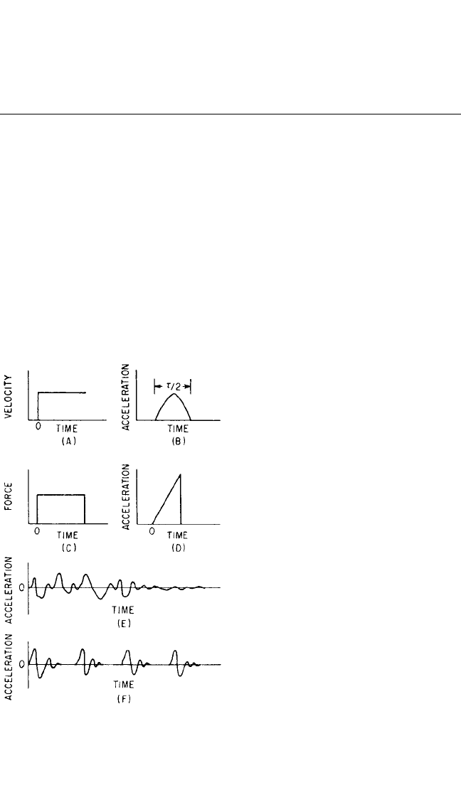
inertial forces in the item under test. The types of shock shown in Fig. 26.1 are clas-
sified as (A) through (D), simple shock pulses, whose shapes can be expressed in a
practical mathematical form; (E), single complex shock; and (F), a multiple shock. In
contrast to a simple shock pulse specification, the motions illustrated in Fig. 26.1 (E)
and (F) often are the result of a shock test in which the shock testing machine, the
method of mounting, and machine operations were specified.
Velocity Shocks. A velocity shock is produced by a sudden change in the net
velocity of the structure supporting the item under test. When the duration of the
shock is short compared to the periods
of the principal natural frequencies of
the item under test, a velocity shock is
said to have occurred. Figure 26.1A
shows a nearly instantaneous change in
velocity. The shocks shown in Fig. 26.1B,
C, and D are also considered velocity
shocks if the above shortness criterion is
met.Velocity shocks produce substantial
energy at the principal natural frequen-
cies of the item under test. This is illus-
trated in Figs. 26.2 and 26.3, which show
the shock response spectra (computed
with a zero damping ratio) for the half-
sine and sawtooth acceleration pulses in
Fig. 26.1A and B, respectively. Note in
both cases that the values of the velocity
shock response spectra are uniform at
all frequencies below about Tf = 0.2.
Hence, from Eq. (26.1), they have the
potential to cause substantial damage to
the basic structure of the item under
test, assuming the item has natural fre-
quencies below f = 0.2/T Hz.
Displacement Shocks. Some shock
test machines produce a sequence of
two or more velocity shocks with equal
and opposite velocity magnitudes such
that the test item experiences no net
velocity change. For example, the half-
SHOCK TESTING MACHINES 26.5
FIGURE 26.1 Characteristic types of shocks.
(A) Velocity shock, or step velocity change. (B)
Simple half-sine acceleration shock pulse. (C)
Rectangular force pulse. (D) Sawtooth accelera-
tion pulse. (E) Single complex shock. (F ) Multi-
ple shock.
8434_Harris_26_b.qxd 09/20/2001 11:54 AM Page 26.5
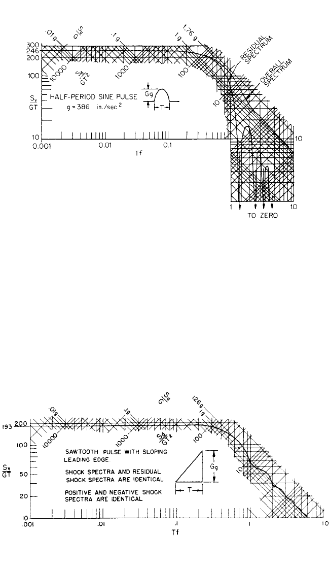
FIGURE 26.3 Shock response spectra of a sawtooth acceleration pulse shown in the inset.
sine acceleration pulse in Fig. 26.1B might be followed by a second half-sine pulse of
equal magnitude in the opposite direction. If the time between the two equal and
opposite acceleration pulses is longer than the duration of the individual pulses, a
substantial displacement of the test item between the positive and negative velocity
changes will occur.This type of shock is commonly called a displacement shock. Such
shocks have a damage potential similar to that of velocity shocks.
High-Frequency Shocks. Metal-to-metal impacts that do not result in a net
velocity change of the item under test create high-acceleration, high-frequency oscil-
lations in the vicinity of the impact. Figure 26.1E and F are examples of high-
26.6 CHAPTER TWENTY-SIX, PART I
FIGURE 26.2 Residual and overall shock response spectra of the half-sine acceler-
ation pulse shown in the inset.
8434_Harris_26_b.qxd 09/20/2001 11:54 AM Page 26.6