Harris C.M., Piersol A.G. Harris Shock and vibration handbook
Подождите немного. Документ загружается.


frequency shocks. Since the frequency range of these shocks often exceeds the prin-
cipal natural frequencies of the item under test, the shocks usually are not readily
transmitted far from the point of their creation. Consequently, this type of shock
lacks the damage potential of velocity shocks for all but small and/or brittle compo-
nents of the item under test. Common sources of high-frequency shocks include
pyrotechnic devices, which produce what are commonly referred to as pyroshocks.
Laboratory machines and techniques for the simulation of pyroshocks are detailed
separately in Chap. 26, Part II.
SIMPLE SHOCK PULSE MACHINES
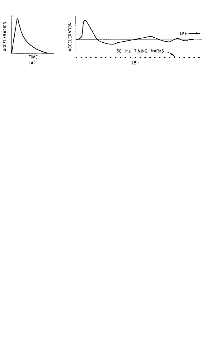
Although shocks encountered in the field are usually complex in nature (for exam-
ple, see Fig. 26.1E), it is frequently advantageous to simulate a field shock by a shock
of mathematically simple form. This permits designers to calculate equipment
response more easily and allows tests to be performed that can check these calcula-
tions. This technique is additionally justifiable if the pulses are shaped so as to pro-
vide shock response spectra similar to those obtained for a suitable average of a
given type of field conditions. Machines are therefore built to provide these simple
shock motions. However, note that the motions provided by actual machines are
only ideally simple.The ideal outputs may be given as nominal values; the actual out-
puts can only be determined by measurement.
Drop Tables. A great variety of drop testers are used to obtain acceleration pulses
having magnitudes ranging from 80,000g down to a few g. The machines each
include a carriage (or table) on which the item under test is mounted; the carriage
can be hoisted up to some required height and dropped onto an anvil. Guides are
provided to keep the carriage properly oriented. When large velocity changes are
required, the carriage may be accelerated downward by a means other than gravity.
Frequently, parts of the carriage, associated with its lifting and guiding mechanism,
are flexibly mounted to the rigid part of the carriage structure that receives the
impact. This is to isolate the main carriage structure from its flexible appendages so
as to retain the simple pulse structure of the stopping acceleration.
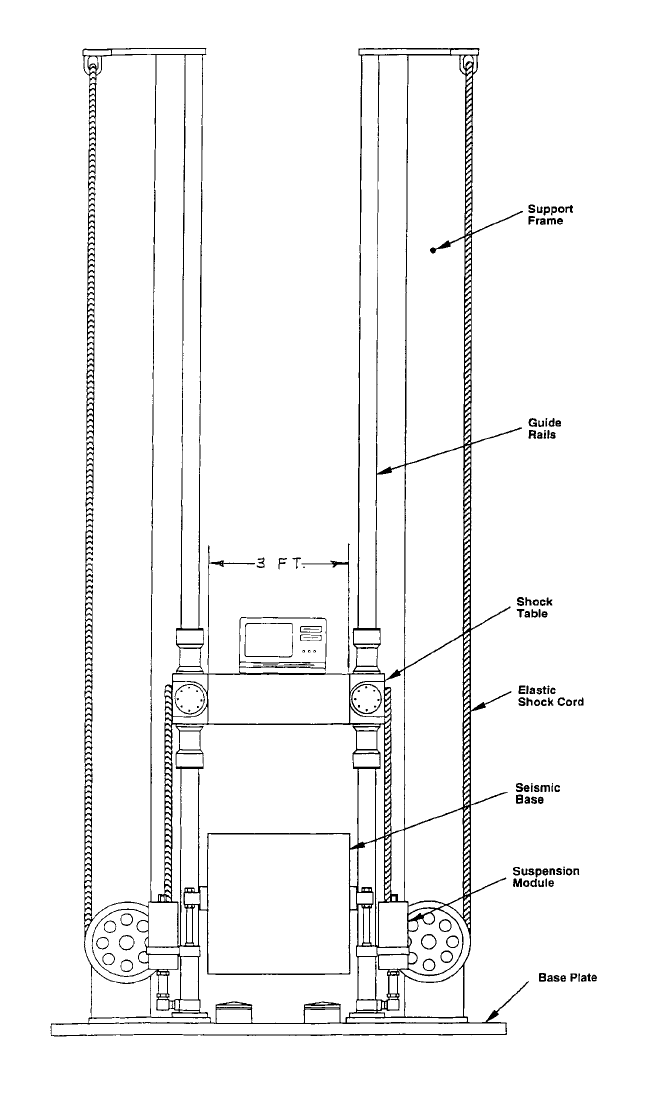
A typical drop table machine is shown in Fig. 26.4. The desire acceleration pulse
shape is obtained using a programming device between the impacting surfaces.
Devices ranging from liquid programmers to simple pads of elastomeric materials
can be used. Note the shock cords that accelerate the table to create velocities
beyond those that can be obtained with a free fall. Machines of this type can produce
acceleration waveforms that closely approximate many different types of velocity
shocks, such as the half-sine and terminal sawtooth acceleration pulses in Fig. 26.1A
and B, respectively.
Air Guns. Air guns frequently are used to impart large accelerations to pistons on
which items under test can be attached. The piston is mechanically retained in posi-
tion near the breech end of the gun while air pressure is built up within the breech.
A quick-release mechanism suddenly releases the piston, and the air pressure pro-
jects the piston down the gun barrel. The muzzle end of the gun is closed so that the
piston is stopped by compressing the air in the muzzle end.Air bleeder holes may be
placed in the gun barrel to absorb energy and to prevent an excessive number of
oscillations of the piston between its two ends.
A variety of such guns can provide the acceleration pulses shown in Fig. 26.5A
and B. The peak accelerations may extend from a maximum of about 1000g for the
SHOCK TESTING MACHINES 26.7
8434_Harris_26_b.qxd 09/20/2001 11:54 AM Page 26.7
26.8 CHAPTER TWENTY-SIX, PART I
FIGURE 26.4 Drop-table arrangement for use with programming devices between
the impacting surfaces. (Courtesy of MTS Systems Corp.)
8434_Harris_26_b.qxd 09/20/2001 11:54 AM Page 26.8
large-diameter (21 in, 53 cm) guns up to 200,000g for small-diameter (2 in, 5 cm)
guns. The pulse length varies correspondingly from about 50 to 3 milliseconds. The
maximum piston velocity varies from about 400 to 750 ft/sec (122 to 229 m/sec). The
maximum velocities are not dependent upon piston diameter.
High-acceleration gas guns have been developed for testing electronic devices.
The items under test are attached to the piston. The gun consists of a barrel (cylin-
der) that is closed at the muzzle end but which has large openings to the atmosphere
a short distance from the muzzle end. The piston is held in place while a relatively
low-pressure gas (usually air or nitrogen) is applied at the breech end of the gun.The
piston is then released, whereby it is accelerated over a relatively long distance until
it reaches the position along the length of the cylinder that is open to the atmo-
sphere. This initial acceleration is of relatively small magnitude. After the piston has
passed these openings, it is stopped by the compression of gas in the short closed end
of the cylinder. This results in a reverse acceleration of relatively large magnitude.
(Sometimes an inert gas, such as nitrogen, is used in the closed end to prevent explo-
sions which might be caused by oil particles igniting under the high temperatures
incident to the compression.) Thus, in contrast to the previously described devices,
the major acceleration pulse is delivered during stopping rather than starting. An
advantage of this latter technique is that the difficult problem of constructing a
quick-release mechanism for the piston, which will work satisfactorily under the
large forces exerted by the piston, is greatly simplified.
Vibration Machines. Electrodynamic, hydraulic, and pneumatic vibration
machines provide a ready and flexible source of shock pulses, so long as the pulse
requirements do not exceed the force and motion capabilities of the selected
machine. See Chap. 25 for information.
Test Load Reactions. In the above description of the output of shock machines
designed to deliver simple shock pulses of adjustable shapes, it is assumed that the
load imposed on the machine by the item under test has little effect on the shock
motions. This is true only when the effective weight of the load is negligibly small
compared with that of the shock machine mounting platform. If the effective weight
of the load is independent of frequency, i.e., if it behaves as a rigid body, it is simple
to compensate for the effect of the load by adjusting machine parameters. However,
when the load is flexible and the reactions of excited vibrations are appreciable, the
motions of the shock machine platform are complex. Specifications involving the
use of these types of machines should require that the mounting platform have no
significant natural frequencies below a specified frequency. The weight of this plat-
form together with that of all rigidly attached elements, exclusive of the test load,
SHOCK TESTING MACHINES 26.9
FIGURE 26.5 Typical acceleration-time curves for (A) 5-in. (13-cm) air gun; (B) 21-in. (53-cm) air
gun.
8434_Harris_26_b.qxd 09/20/2001 11:54 AM Page 26.9

also should be specified. Pulse shapes may then be specified for motions of this plat-
form or for the platform together with given dead-weight loads. These may be spec-
ified as nominal values for test loads, but it is neither practical nor desirable to
require that the pulse shape be maintained in simple form for complex loads of con-
siderable mass.
COMPLEX SHOCK PULSE MACHINES
Because of the infinite variety of shock motions possible under field conditions, it is
not practical or desirable to construct a shock machine to reproduce a particular
shock that may be encountered in the field. However, it is sometimes desirable to
simulate some average of a given type of shock motion. To accomplish this may
require that the shock machine deliver a complex motion. A shock of this type can-
not be specified easily in terms of the shock motions, since the motions are very com-
plex and dependent on the nature and the mounting of the load. It is customary,
therefore, to specify a test in terms of a shock machine, the conditions for its opera-
tion, and a method of mounting the item under test.
High-Impact Shock Machines. The Navy high-impact shock machines are
designed to simulate shocks of the nature and intensity that might occur on a ship
exposed to severe but sublethal, noncontact, underwater explosions. Such severe
shocks produce motions that extend throughout the ship. Equipment intended for
shipboard use can demonstrate its ability to withstand the shock simulations pro-
duced by these high-impact shock machines and thus be considered capable of with-
standing the actual underwater explosion environment.
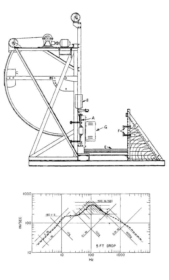
Lightweight Machines.
3–5
The lightweight high-impact shock machine, shown
in Fig. 26.6, is used for testing equipment weighing up to about 350 lb (159 kg).
Equipment under test is attached to the anvil plate A. Method of attachment is con-
strained to resemble closely the eventual field attachments.The anvil is struck on the
backside by the pendulum hammer C, or the anvil is rotated 90° on a vertical axis
and struck on the end by the pendulum hammer. The drop hammer B can be made
to strike the top of the anvil, thus providing principal shock motions in the third
orthogonal direction. Shock response spectra of shock motions generated by this
machine are shown in Fig. 26.7 (these results were computed with a damping ratio of
about 0.01). The spectrum for the motion at the center of the plate illustrates the
amplification of the spectrum level at a natural frequency of the plate (about 100
Hz) and some attenuation at higher frequencies.
Medium-Weight Machines.
4,5
This machine is used to test equipment that, with
its supporting structures, weighs up to 7400 lb (3357 kg). Shown in Fig. 26.8, this
machine consists principally of a 3000-lb (1361-kg) hammer and a 4500-lb (2041-kg)
anvil. Loads are not attached directly to the rigid anvil structure but rather to a
group of steel channel beams which are supported at their ends by steel members,
which in turn are attached to the anvil table. The number of channels employed is
dependent on the weight of the load and is such as to cause the natural frequency of
the load on these channels to be about 60 Hz. The hammer can be dropped from a
maximum effective height of 5.5 ft (1.68 m). It rotates on its axle and strikes the anvil
on the bottom, giving it an upward velocity. The anvil is permitted to travel a dis-
tance of up to 3 in. (7.6 cm) before being stopped by a retaining ring.The machine is
mounted on a large block of concrete which is mounted on springs to isolate the sur-
rounding area from shock motions. The general nature of the shock is complex, sim-
26.10 CHAPTER TWENTY-SIX, PART I
8434_Harris_26_b.qxd 09/20/2001 11:54 AM Page 26.10
SHOCK TESTING MACHINES 26.11
FIGURE 26.6 Navy high-impact shock machine for lightweight equipment.
FIGURE 26.7 Shock response spectra for a 5-ft back blow with a 57-lb (25.9-
kg) load on the mounting plate for four different lightweight high-impact shock
machines.
8434_Harris_26_b.qxd 09/20/2001 11:54 AM Page 26.11
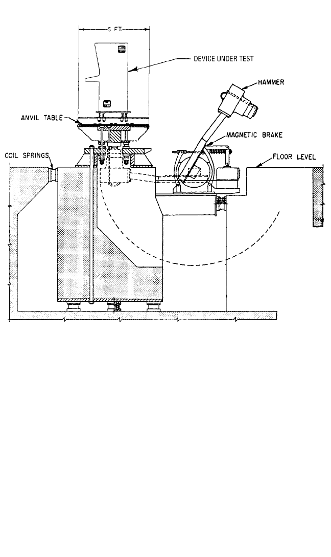
FIGURE 26.8 High-impact shock machine for medium-weight equipment.
ilar to that of the lightweight machine. Little of the high-amplitude, high-frequency
components of the shock motions are transmitted to the load.
Heavy-Weight Machines.
4–6
The floating shock platform (FSP), and the large
floating shock platform (LFSP) are high-load-capacity shock machines of the high-
impact category. They are rectangular barges fitted with semicylindrical canopies
within which test items are installed as they are aboard ship.The shock motions com-
prising the test series are generated by detonating explosive charges beneath the
water surface at various distances.
The FSP is 28 ft (8.5 m) long by 16 ft (4.9 m) wide and has a maximum load capac-
ity of 60,000 lb (27,216 kg). Its available internal volume is about 26 ft (7.9 m) by 14
ft (4.3 m) by 15 ft (4.6 m) high to the center of the canopy. The charges for the suc-
cessive shots of the test sequence are all 60 lb (27 kg) at a depth of 24 ft (7.3 m). The
charge standoff, the horizontal distance from the near side of the FSP, is shortened
for each shot to a final value of 20 ft (6.1 m). Design shock response spectra for the
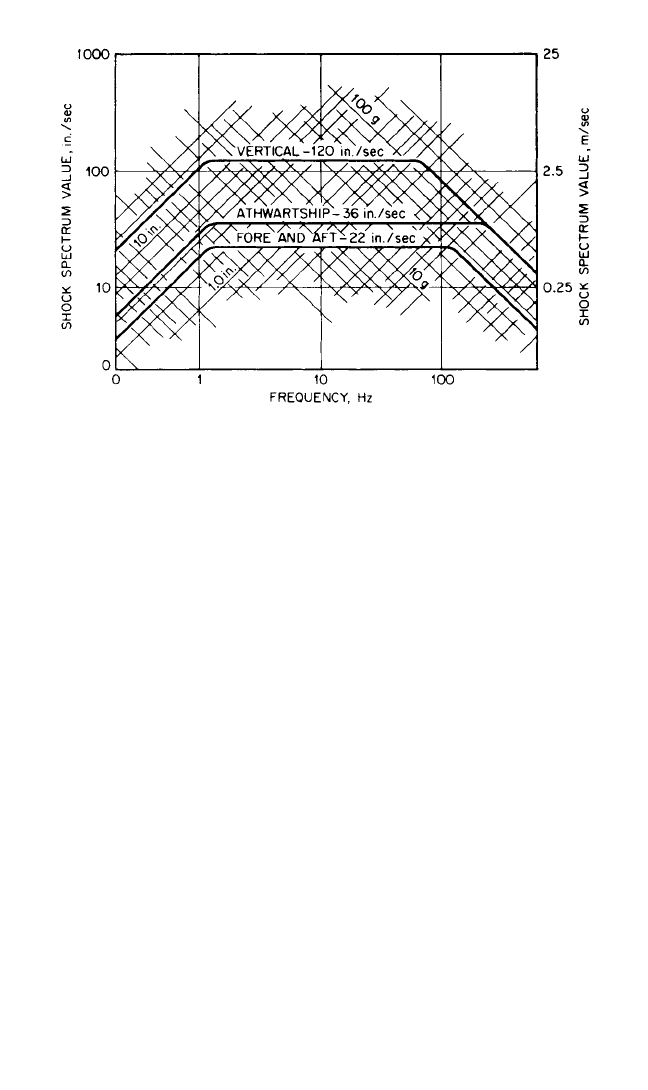
FSP are shown in Fig. 26.9.
The LFSP is 50 ft (15.2 m) long by 30 ft (9.1 m) wide with a maximum load capac-
ity of 400,000 lb (181,440 kg) and an internal volume of about 48 ft (14.6 m) by 28 ft
(8.5 m) by 34 ft (10.4 m) high to the center of the canopy. The charge size is 300 lb
(136.1 kg), and the charge depth is 20 ft (6.1 m); the standoff is decreased for each shot
26.12 CHAPTER TWENTY-SIX, PART I
8434_Harris_26_b.qxd 09/20/2001 11:54 AM Page 26.12
to a final value of 50 ft (15.2 m).At the crossover load of 30,000 to 40,000 lb (13,640 to
18,180 kg), the LFSP provides a shock environment equivalent to the FSP.Therefore,
data in Fig. 26.9 can be used in design of equipment scheduled for LFSP shock testing.
Hopkinson Bar. When shock testing requires extremely high g levels for light
loads (for example, calibration of accelerometers), the Hopkinson bar has proven
useful.A controlled velocity projectile is impacted on the end of a metallic bar, caus-
ing a stress wave of known magnitude to travel along the bar. Often, the magnitude
of the stress wave is measured as it passes the middle of the bar.The item under test
is attached to the extreme end of the bar and experiences a high g rapid rise time
acceleration when the stress wave arrives at that position. See Fig. 18.12.
MULTIPLE-IMPACT SHOCK MACHINES
Many environments, particularly those involving transportation, subject equipment
to a relatively large number of shocks.These are of lesser severity than the shocks of
major intensity that have been considered above, but their cumulative effect can be
just as damaging. It has been observed that components of equipment that are dam-
aged as a result of a large number of shocks of relatively low intensity are usually dif-
ferent from those that are damaged as a result of a few shocks of a relatively high
intensity. The damage effects of a large number of shocks of low intensity cannot
generally be produced by a small number of shocks of high intensity. Separate tests
are therefore required so that the multiple number of low-intensity shocks are prop-
erly emulated.
Vibration Machines. Electrodynamic, hydraulic, and pneumatic vibration test-
ing machines provide a ready and flexible source of multiple shock pulses so long
as the pulse requirements do not exceed force and motion capabilities of the
SHOCK TESTING MACHINES 26.13
FIGURE 26.9 Design shock response spectra for the floating shock platform.
The lower cutoff frequency is 1.15 Hz for all directions. The upper cutoff frequen-
cies are vertical, 67 Hz; athwartship, 220 Hz; fore and aft, 125 Hz.
8434_Harris_26_b.qxd 09/20/2001 11:54 AM Page 26.13

selected machine. They can be programmed to provide a series of different shock
pulses or to repeat a particular shock motion as many times as desired and to estab-
lish the necessary initial conditions prior to each shock pulse. See Chap. 25 for more
information.
ROTARY ACCELERATOR
A quick-starting centrifuge can is used to quickly attain and maintain an accelera-
tion for a long period of time. The accelerator consists of a rotating arm which is
suddenly set into motion by an air-operated piston assembly. The test object is
mounted on a table attached to the outer end of the arm.The table swings on a pivot
so that the resultant direction of the acceleration is always along a fixed axis of the
table. Initially the resultant acceleration is caused largely by angular acceleration of
the arm, so this axis is in a circumferential direction. As the centrifuge attains its full
speed, the acceleration is caused primarily by centrifugal forces, so this table axis
assumes a radial direction. These machines are built in several sizes. They require
between 5 and 60 milliseconds to reach the maximum value of acceleration. For
small test items (8 lb, 3.6 kg), a maximum acceleration of 450g is attainable; for
heavy test items (100 lb, 45.4 kg), the maximum value is about 40g.
REFERENCES
1. Gaberson, H. A., and R. H. Chalmers: Shock and Vibration Bull., 40(2):31 (1969).
2. Piersol, A. G.: J. IEST, 44(1):23 (2001).
3. “Specification for the Design, Construction, and Operation of Class HI (High Impact)
Shock Testing Machine for Lightweight Equipment,” American National Standards Insti-
tute Document ANSI S2.15-1973.
4. “Methods for Specifying the Performance of Shock Machines,” American National Stan-
dards Institute Document ANSI S2.14-1973.
5. Military Specification. “Shock Tests HI (High Impact); Shipboard Machinery, Equipment
and Systems, Requirements for,” MIL-S-901D (Navy), March 17, 1989.
6. Clements, E. W.: “Characteristics of the Navy Large Floating Shock Platform,” U.S. Naval
Research Laboratory Report 7761, 15 July 1974. (Obtainable from the Shock and Vibration
Information Analysis Center, Booz-Allen & Hamilton Incorporated, 2231 Crystal Drive,
Suite 711, Arlington, VA 22202.)
26.14 CHAPTER TWENTY-SIX, PART I
8434_Harris_26_b.qxd 09/20/2001 11:54 AM Page 26.14

CHAPTER 26, PART II
PYROSHOCK TESTING
Neil T. Davie
Vesta I. Bateman
INTRODUCTION
Pyroshock, also called pyrotechnic shock, is the response of a structure to high-
frequency (thousands of hertz), high-magnitude stress waves that propagate
throughout the structure as a result of an explosive event such as the explosive charge
to separate two stages of a multistage rocket. The term pyrotechnic shock originates
from the use of propellants such as black powder, smokeless powder, nitrocellulose,
and nitroglycerin in devices common to the aerospace and defense industries. These
devices include pressure squibs, explosive nuts and bolts, latches, gas generators, and
air bag inflators.
1
The term pyroshock is derived from pyrotechnic shock, but both
terms are used interchangeably in the industry and its literature. A pyroshock differs
from other types of mechanical shock in that there is very little rigid-body motion
(acceleration, velocity, and displacement) of a structure in response to the pyroshock.
The pyroshock acceleration time-history measured on the structure is oscillatory and
approximates a combination of decayed sinusoidal accelerations with very short
duration in comparison to mechanical shock described in Part I of this chapter. The
characteristics of the pyroshock acceleration time-history vary with the distance from
the pyroshock event. In the near field, which is very close to the explosive event, the
pyroshock acceleration time-history is a high-frequency, high-amplitude shock that
may have transients with durations of microseconds or less. In the far field, which is
far enough from the event to allow structural response to develop, the acceleration
time-history of the pyroshock approximates a combination of decayed sinusoids with
one or more dominant frequencies. The dominant frequencies are usually much
higher than that in a mechanical shock and reflect the local modal response of the
structure.The dominant frequencies are generally lightly damped.However, since the
frequencies are so high, it typically takes less than 20 milliseconds for the pyroshock
response to dampen out and return to zero. Satellite, aerospace, and weapon compo-
nents are often subjected to pyroshocks created by devices such as explosive bolts
and pyrotechnic actuators. Pyroshock structural response is also found in ground-
based applications in which there is a sudden release of energy, such as the impact of
a structure by a projectile.
Pyroshock was once considered to be a relatively mild environment due to its
low-velocity change and high-frequency content. Although it rarely damages struc-
tural members, pyroshock can easily cause failures in electronic components that are
sensitive to the high-frequency pyroshock energy. The types of failures caused by
pyroshock commonly include relay chatter, hard failures of small circuit compo-
26.15
8434_Harris_26_b.qxd 09/20/2001 11:54 AM Page 26.15

nents, and the dislodging of contaminants (e.g., solder balls), which cause short cir-
cuits. A significant number of flight failures have been attributed to pyroshock com-
pared to other types of shock or vibration sources, and, in one case, an extensive
database of the failures has been compiled.
2
Designers must rely on testing for qual-
ifications of their systems and components that will be exposed to pyroshock envi-
ronments in the absence of analytical techniques to predict structural response to a
pyroshock. Failures can be reduced by implementing a qualification testing program
for components exposed to a pyroshock environment. This chapter describes the
characteristics of pyroshock environments, measurement techniques, test specifica-
tions, and simulation techniques.
PYROSHOCK CHARACTERISTICS
COMPARISON OF NEAR-FIELD AND FAR-FIELD CHARACTERISTICS
The detonation of an explosively actuated device produces high-frequency tran-
sients in the surrounding structure. The specific character of these acceleration tran-
sients depends on various parameters including: (1) the type of pyrotechnic source,
(2) the geometry and properties of the structure, and (3) the distance from the
source. Due to the endless combinations of these parameters, sweeping conclusions
about pyroshock characteristics cannot be made; however the following paragraphs
describe useful characteristics of typical pyroshock environments.
A pyrotechnically actuated device produces a nearly instantaneous pressure on
surfaces in the immediate vicinity of the device. As the resulting stress waves propa-
gate through the structure, the high-frequency energy is gradually attenuated due to
various material damping and structural damping mechanisms. In addition, the high-
frequency energy is transferred or coupled into the lower-frequency modes of the
structure. The typical pyroshock acceleration transient thus has roughly the appear-
ance of a multifrequency decayed sinusoid (i.e., the envelope of the transient decays
and is symmetric with respect to the positive and negative peaks).The integral of the
typical transient also has these same characteristics.
3
In most cases, the initial portion
of the acceleration transient exhibits a brief period during which the amplitudes of
the peaks are increasing prior to the decay described above (see Figs. 26.10 and
26.11). This is a result of the interaction of stress waves as they return from various
locations in the structure.
A pyrotechnically actuated device imparts very little impulse to a structure since
the high forces produced are acting for only a short duration and are usually inter-
nal to the structure. The net rigid body velocity change resulting from a pyroshock is
thus very low relative to the peak instantaneous velocity seen on the integral of the
acceleration transient. Rigid body velocity changes are commonly less than 1 meter
per second. The duration of a pyroshock transient depends on the amount of damp-
ing in a particular structure, but it is commonly 5 to 20 milliseconds in duration.
Pyroshock may be subdivided into two general categories: Near-field pyroshock
occurs close to the pyrotechnic source before significant energy is transferred to
structural response. It is dominated by the input from the source and contains very
high-frequency and very high g energy. This energy is distributed over a wide fre-
quency range and is not generally dominated by a few selected frequencies. Far-field
pyroshock environments are found at a greater distance from the source where sig-
nificant energy has transferred into the lower-frequency structural response. It con-
tains lower frequency and lower g energy than near-field pyroshock; most of the
26.16 CHAPTER TWENTY-SIX, PART II
8434_Harris_26_b.qxd 09/20/2001 11:54 AM Page 26.16