Henini M. Handbook of Self Assembled Semiconductor Nanostructures for Novel devices in Photonics and Electronics
Подождите немного. Документ загружается.

Quantum Dot Infrared Photodetectors by Metal-Organic Chemical Vapour Deposition 629
In the meantime, while charges are being emitted from the dot, other charges are being
injected from the electrode. In the steady state, as many are coming in as are going out. The elec-
trode injection rate I
inj
, assuming injection into a drifting state, rather than a pure eigenstate, is
given by
IeAdEfEEF
m
eF
EE
b
()() {[ ]ρμ exp
*
/
/
24
3
2
12
32
⎛
⎝
⎜
⎜
⎜
⎞
⎠
⎟
⎟
⎟
⎟
⎡
⎣
⎢
⎢
⎢⎢
⎤
⎦
⎥
⎥
⎥
∫∫
0
E
E
b
B
eA dE E f E F ρμ()()
(21.23)
where the fi rst term is Fowler–Nordheim tunnelling through the injection barrier, A is the elec-
trode area, and f ( E ) the Fermi function. The second term is the band contribution. The equality
of injection current to bulk current establishes the Fermi level in the bulk.
Assuming the system is roughly neutral, it follows that quantum dots which have just emitted
will eventually be replenished by charges which are fl owing about in the band. The typical times-
cale 1/ C
be
for reoccupation is 10
9
to 10
1 0
s, which is much longer than the typical transit time
L / μ F 10
12
s. So it follows that photoexcited charges will be fl owing around the circuit at very
high speeds before they get captured again.
C
be
W
eg
W
ge
W
eb
W
gb
N
b
N
e
N
g
N
tot
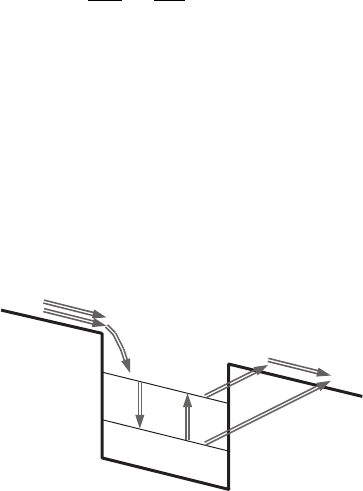
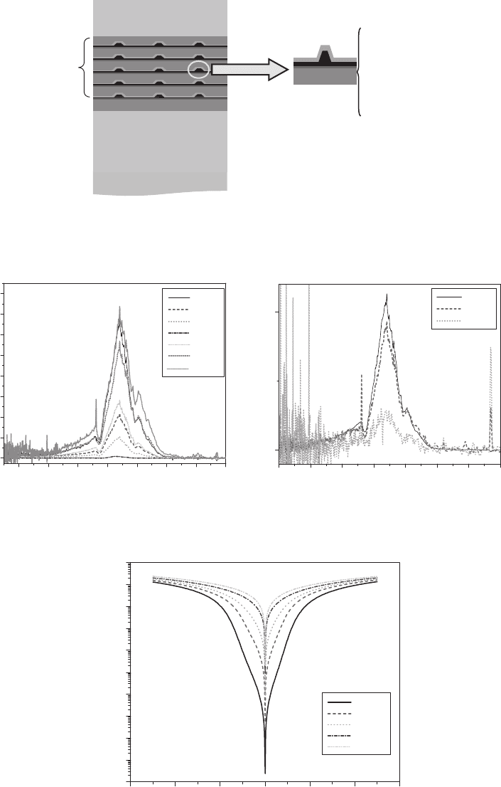
Figure 21.6 Schematic diagram for the processes of the electrons that escape from, capture into, excite and recom-
bine in the dot.
The theory of the dark current is developed using a rate equation approach. In Fig. 21.6 , the
schematic diagram of the processes involved in the dark situation is shown in a two-level system.
But this can be easily expanded into a multi-level system. N
tot
is the number of electrons which
are provided to a quantum dot through the current injection from the electrode and proportional
to the density of the quantum dots in one layer. N
e
and N
g
are the numbers of the electrons stay-
ing in the excited states and the ground state, respectively. N
b
is the number of electrons which
are emitted from a dot to the barrier continuum. C
be
is the capture rate from the band continuum
to the excited state. W
eb
and W
gb
are the escape rates from each quantum level ( e : excited state
and g : ground state) to the band continuum. These escape rates can be obtained with the same
method as the escape rate for the responsivity, Eq. 21.20, because the photoexcited electrons and
electrons under dark condition in a dot follow the same routes such as thermal activation and
tunnelling. W
eg
is the transition rate from the excited state to the ground state. W
ge
is the transi-
tion rate from the ground state to the excited state. Because of the charge conservation:
NNNN
tot b g e
(21.24)
should be satisfi ed at any time. In Eq. 21.24, N
tot
is a constant which is determined as
NAeFFN
tot d
•
μ() .
(21.25)
But the other numbers N
b
, N
g
, and N
e
change under circumstances. For the steady state, detailed
balance rate equations can be obtained for each N .
CH021-I046325.indd 629CH021-I046325.indd 629 6/27/2008 5:47:59 PM6/27/2008 5:47:59 PM

630 Handbook of Self Assembled Semiconductor Nanostructures for Novel Devices in Photonics and Electronics
If we solve the above equations to get the relation between N
b
and N
tot
, we can get:
N
NWW WW WW
WW WW WW C W
b
tot ebgb ebge eggb
eb gb eb ge eg gb be e
()
()(
gggbge
tot eb
eb be e
gg
e
WW
NW
WC WW
)
()
≈
1/
(21.26)
Here we use the approximation that W
gb
is very small and can be neglected in most cases.
Because W
eg
/ W
ge
is the very occupation probability in the quantum dot level “ e ” which obeys a
Fermi distribution with a self-consistent Fermi level and temperature, Eq. 21.26 becomes:
N
NWf
CffWC
b
tot eb e
be e e eb be
[( )]
.
1/
(21.27)
In general, the quantum dot has more than two levels. In the multi-level case, the number of
electrons emitted from each level and therefore the dot emission currents from each level can add
up. The general expression for the dot emission current can be written:
I
Ae F Fn
C
fW
fWC
W
dot
d
be
ssb
ssbbe
s
sb s
μ
ν
()
()1/
∑
⎧
⎨
⎪
⎪
⎩
⎪
⎪
⎫
⎬
⎪
⎪
⎭
⎪
⎪
bbs
sb sb
sb
sb
g
EkT aE E eF Eexp / exp exp / exp
//
[][ ][ ][ 243
12 32
γγ //
exp exp /
/
kT
aE eFa kT
sb
]
[][]12
12
γ
(21.28)
where A is area, e is the electronic charge, F is the electric fi eld, μ ( F ) is band mobility and n
d
is the
density of quantum dots. f
s
is the Fermi function at level “ s ” and the Fermi level has to be deter-
mined self-consistently for each bias V and temperature T by matching injection and quantum
dot escape current. W
sb
is the escape rate from each quantum level s to the band continuum. For
simplicity we defi ne activation energy, also
2fn
s
s
dot
∑
〈〉
which is the mean number of elec-
trons in a dot:
I
Ae F FN
nC
gEFkT
dot
d
ebe
ssc D
μ
ν
()
()
[()].
1
exp /
(21.29)
The total current across the device area includes also the uniform band contribution as in Eq.
21.23. The prefactor g
s
ν
sc
is the product of the density of fi nal states and the sum over all paths
from a level “ s ” to the continuum “ c ” .
21.2.8 Modelling of detectivity
One of the measures for device performances is the specifi c detectivity D *, defi ned as the ratio of
responsivity over the square root of the dark current density at a given bandwidth multiplied by
the gain [13] .
This can be written in the elegant form (unit band width, D* in cmHz
1/2
/W):
D
R
eg I
D
*
*
/
[()]
.
12
(21.30)
Theoretical modelling of peak detectivity Eq. 21.30 can be rewritten combining Eq. 21.15 and
Eq. 21.29 as follows:
D
Q
ee
T
AN
ec
t
kT
ec
EkT
ec
*
()
〈〉
〈〉
⎡
⎣
⎢
⎢
⎤
⎦
⎥
⎥
〈,〉ν
νν ν
αω
12
0
12
/
/
/
/Δ
dd
EkTEkT
e
Dec
ω
()//2
(21.31)
where Q N
d
AL is the total number of quantum dots in the device.
CH021-I046325.indd 630CH021-I046325.indd 630 6/27/2008 5:47:59 PM6/27/2008 5:47:59 PM

Quantum Dot Infrared Photodetectors by Metal-Organic Chemical Vapour Deposition 631
21.2.9 Summary
The origins of novel properties and predicted device improvement of quantum dots devices
are discussed. It has been shown that the steep δ -function density of states of quantum dots is
responsible for most of the improvements compared with QWIP, including high-temperature
operation, high responsivity, high selectivity and narrow spectrum. Another advantage is nor-
mal incidence detection due to 3D confi nement. It has been predicted that with improved quan-
tum dots fabrication QDIP should outperform QWIP.
21.3 InP-based QDIP materials growth and characterizations
The material growth is the most challenging step in QDIP device fabrication. In this section, the
details regarding the MOCVD growth and characterization of InP, GaInAs, AlInAs materials and,
most importantly, InAs quantum dots are described. The next chapter will present the detector
characterization for the structures fabricated from these materials.
Table 21.1 Physical properties of InAs and InP.
T (K) InAs InP
Crystal structure Cub (ZnS) Cub (ZnS)
Lattice constant (Å) 300 6.0584 5.8688
Energy gap (eV) 300 0.36 1.35
0 0.41 1.42
Melting point (K) 1215 1335
Coeffi cient of thermal expansion
(10
6
K
1
)
300 4.52 5.0
m
e
*/ m
0
4 0.024 0.077
m
lh
*/ m
0
4 0.025 0.12
m
hh
*/ m
0
4 0.37 0.55
m
sos
*/ m
0
4 0.14 0.12
Electron mobility (cm
2
/V s) 300
77
3 10
4
8 10
4
5 10
3
4 10
4
Hole mobility (cm
2
/V s) 300 200 150
77 500 1200
Intrinsic carrier Conculation (cm
3
)
300
9 10
14
1 10
8
Static dielectric constant 15.15 12.5
High-frequency dielectric constant 12.25 9.61
Elastic moduli (10
12
dyn cm
2
)
300
C
11
8.329 10.11
C
12
4.526 6.61
C
44
3.959 4.56
Refractive index 3.44 3.35
Optical phonon (cm
1
)
242 320
LO 220 288
T O
21.3.1 Growth and characterization of matrix material
“ Epi-ready ” semi-insulating (SI) InP substrates are the templates for all the growths in this work.
All of the growths in this work are done with an Emcore D125 low-pressure (LP) MOCVD. First
of all, homoepitaxial growth of InP is optimized. The growth of high-quality InP is important
since it serves as the nucleation layer for the entire growth as well as the barrier in the active
region. InP has a wide growth window. Usually within one growth of a device structure, different
growth temperatures are needed. For example, the bottom and top InP contact layers are usu-
ally grown at a higher, optimum temperature to ensure the excellent quality; while a much lower
CH021-I046325.indd 631CH021-I046325.indd 631 6/27/2008 5:48:00 PM6/27/2008 5:48:00 PM
632 Handbook of Self Assembled Semiconductor Nanostructures for Novel Devices in Photonics and Electronics
temperature will be used for the InP barrier in the active region to accommodate the growth of
InAs QDs at lower temperature.
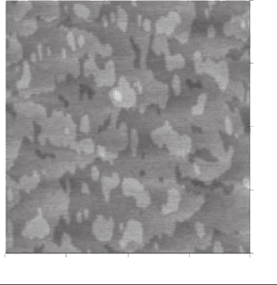
The as-grown InP sample shows a mirror-like surface. The 1 μ m 1 μ m atomic force micro-
scope (AFM) scan image shows a very smooth surface with clear atomic steps and a roughness
(RMS) of 1.16 Å, indicating excellent structural quality.
GaInAs is an important alloy because Ga
0.47
In
0.53
As is lattice matched to InP and has a lower
band gap energy. By using Ga
0.47
In
0.53
As as the matrix, the confi nement, and thus the inter-
subband transition energy, of InAs QD can be tuned. For example, GaInAs QWs can be inserted
between InAs QD and InP barrier to form a “ dot in a well ” structure. By changing the thickness
or the composition of this GaInAs layer, the detecting wavelength may be tuned. Besides, it is also
found experimentally that by using GaInAs the form and size of the QD can be changed, as will
be shown later.
As part of the active region, the GaInAs layer has to be grown at the same temperature for
QDs. For some of the work here, a growth temperature of 500°C was chosen. In order to opti-
mize the growth of GaInAs, a 0.5 μ m InP buffer layer was fi rst grown at optimum condition. The
temperature was decreased to 500°C and bulk GaInAs was grown. The lattice match condition
was obtained by adjusting the fl ow rates of trimethylindium (TMIn) and triethylgallium (TEGa).
Under the optimized condition, the as-grown sample shows excellent morphology with very
few defects. X-ray diffraction shows an FWHM as small as 32.3 arcsec. AFM shows atomic steps
and an RMS of 1.67 Å for a 1 μ m 1 μ m scan, as shown in Fig. 21.7 .
1.00
1.00
0.75
0.75
0.50
0.500.25
0.25
0
0
m
Figure 21.7 Surface morphology of GaInAs grown at T 500°C (1 μ m 1 μ m AFM).
21.3.2 Growth and characterization of InAs QDs
Growth of InAs quantum dots is not only the most important to the success of the QDIP device
operation but also the most challenging task. So far, most quantum dot research has been done
with In(Ga)As quantum dots on GaAs substrate grown by MBE. Very limited information is
available for InAs quantum dots growth on an InP material system by MOCVD. Various growth
parameters need to be optimized to fi rst enable the growth of quantum dots then change the
form, size and density of QD in a controlled manner. In this section, the growth and characteriza-
tions of single-layer InAs quantum dots on both InP and GaInAs matrix are presented.
21.3.3 Single-layer InAs quantum dots on InP
Self-assembly growth of InAs quantum dots on an InP matrix are fi rst realized. The relation-
ship between growth parameters and characteristics of quantum dots, such as dot size, dot den-
sity, and dot size uniformity, are fully studied. Some important parameters being optimized for
CH021-I046325.indd 632CH021-I046325.indd 632 6/27/2008 5:48:00 PM6/27/2008 5:48:00 PM
Quantum Dot Infrared Photodetectors by Metal-Organic Chemical Vapour Deposition 633
quantum dot growth are growth temperature, growth rate, and V/III ratio. The lower growth
rate is necessary to obtain more uniform-sized dots and prevent the forming the large islands.
For MOCVD, lowering the growth rate is limited technically by the minimum fl ow rate allowed by
mass fl ow control in most cases. The substrate temperature is a dominant factor for the diffusion
process during quantum dot growth. After optimization, the optimum growth parameters will be
used for fi nal QDIP structure growth.
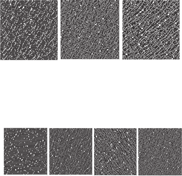
21.3.3.1 Growth temperature
First, the growth temperature was optimized. The structure consists of 0.5 μ m InP buffer grown
at 590°C, then 5 ML InAs grown at 490°C, 500°C and 510°C for three samples. During the QD
growth, the fl ow rate is 50 sccm for both TMIn and arsine. The AFM of these three samples are
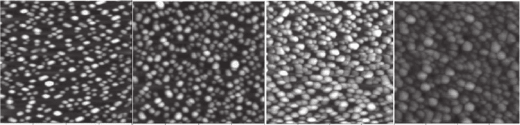
shown and compared in Fig. 21.8 . It can clearly seen that at 490°C, the dot density is low while
at 510°C although dot density increases the large defect density increases too. As a result, 500°C
is chosen as the optimium growth temperature. Too low temperature causes low mobility of the
adsorbed atoms on the substrate surface and too high temperature causes high coalescence rate
between formed quantum dots.
0 2.50 5.0 0 2.50 5.0 0 2.50 5.0
490°C 500°C 510°C
Figure 21.8 Comparison of growth of InAs QD on InP at different temperatures.
0 2.50 5.0 0 2.50 5.0 0 2.50 5.0 0 2.50 5.0
Figure 21.9 Comparison of growth of InAs QD on InP with different arsine fl ow rates: (from left to right)
50 sccm, 25 sccm, 12 scmm and 8 sccm.
21.3.3.2 V/III ratio
The effect of V/III ratio on the formation of QD was studied by changing the fl ow rate of arsine.
The growth temperature was fi xed at 500°C. The growth structures and conditions were identi-
cal as above except that different fl ow rates of arsine were used during growth of InAs QDs. As
shown in Fig. 21.9 , dot density is increased when the V/III ratio is decreased due to increased
movement of the adatoms.
CH021-I046325.indd 633CH021-I046325.indd 633 6/27/2008 5:48:01 PM6/27/2008 5:48:01 PM
634 Handbook of Self Assembled Semiconductor Nanostructures for Novel Devices in Photonics and Electronics
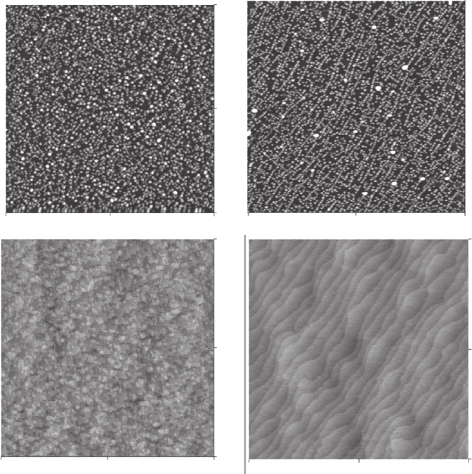
21.3.4 Single-layer InAs quantum dots on GaInAs
InAs QDs were also grown on a GaInAs matrix and compared with those grown on an InP
matrix. The structure consists of 0.5 μ m buffer grown at 590°C, then 3 ML (10 Å) Ga
0.47
In
0.53
As
quantum well and 5 ML InAs QDs at the optimized conditions mentioned above.
The dot size, density and distribution are compared with the results of the InP matrix in Fig.
21.10 . It can be found that even though the GaInAs layer is quite thin, it affects the growth of InAs
QDs. The dot size and distribution are more uniform and the defect size decreases. To explain such
difference, similar structures were grown without the QDs on top. By comparing the results with
and without QD for both GaInAs and InP matrix materials, it can be found that the cause might
be the different surface condition of the matrix materials. For the InP matrix, atomic steps can
be clearly seen and the InAs QDs seem to follow these steps. This argument is reasonable because
most adatoms will incorporate at an atomic step resulting from a miscut substrate. Although the
surface of GaInAs is smooth too, the atomic steps are much smaller and more random, which
may help form more randomly distributed but uniform QDs.
QD
Barrier
GaInAs
InP
0 2.50
2.50
5.00
5.00
0
0 2.50
2.50
5.00
5.00
0
0
2.50 5.00
02.50
2.50
5.00
5.00
0
mm
m
Figure 21.10 Comparison of InAs QD grown on GaInAs (top left) and on InP (top right). Also shown here are the
matrix surfaces before the deposition of InAs QDs.
CH021-I046325.indd 634CH021-I046325.indd 634 6/27/2008 5:48:04 PM6/27/2008 5:48:04 PM
Quantum Dot Infrared Photodetectors by Metal-Organic Chemical Vapour Deposition 635
21.3.4.1 Single-layer QDs growth with dilute arsine
As discussed previously, dot density increases with the decrease of arsine due to increased move-
ment of the adatoms. To follow this trend, a dilute arsine (5% arsine/hydrogen mixture) was used
for the growth of InAs QDs. All the other conditions remained identical. Dilute arsine fl ow rates
of 100, 75, 50 and 25 sccm were used. The AFM images of the QDs are shown in Fig. 21.11 . It
seems that the dot density remains the same when the dilute arsine fl ow changes. However, the
dot form changes from tall and thin to short and fat from 100 sccm to 25 sccm.
1 0.25 0.50 0.75 1.0 1.0 1.00.25 0.50 0.50 0.500.75 0.750.75 1.0 0.25 0.25
100 sccm 75 sccm 50 sccm 25sccm
Figure 21.11 Comparison of growth of InAs QD on GaInAs matrix with different 5% dilute arsine fl ow rates:
(from left to right) 100, 75 , 50 and 25 sccm.
21.3.5 Doping of InAs quantum dots
As discussed in section 21.2, QDs need to be doped for the proper QDIP operation. Doping of
QDs is much different from the doping of bulk semiconductors or quantum wells. Doping may also
affect the quantum dot size and density. Unfortunately, there is no easy way to directly estimate the
doping level in the QDs. However, it is natural to assume that the device that gives the best result
shall have the proper doping. In this work, doping of QDs is optimized by comparing the results
from a batch of samples with the same structure but different doping (silane fl ow rate).
21.3.6 Conclusions
The optimized growth conditions for InP and GaInAs bulk materials and InAs quantum dots are
presented. The growth conditions such as growth temperature, V/III ratio, and matrix material
are optimized. After InP and GaInAs matrix materials are optimized, the growth of InAs quan-
tum dots on both InP and GaInAs matrices are done and compared. The dependence of dot size,
density and distribution upon growth parameters such as growth temperature, V/III ratio, as
well as different matrix material is presented. InAs quantum dots with uniform size, high density
and low defect density are realized under the optimized conditions. Finally, the importance and
method for doping of InAs quantum dots are discussed.
21.4 InP-based QDIP device results
The realization of the QDIPs in this work is performed by the careful optimization of growth and
doping of the InP buffer and barrier, GaInAs matrix and InAs quantum dots. Then the layers are
grown together and optimized again if necessary. Finally, with the methods previously described,
the device structures are grown, fabricated, and tested. This order of design, growth optimiza-
tion, and QDIP operating characteristics is presented in this section.
21.4.1 InAs/GaInAs/InP QDIP
As discussed in the previous section, QDs grown on different matrix materials can result in dif-
ferent dot size, density and uniformity. Previously, InAs QDs were grown after 10 Å GaInAs QW
CH021-I046325.indd 635CH021-I046325.indd 635 6/27/2008 5:48:06 PM6/27/2008 5:48:06 PM

636 Handbook of Self Assembled Semiconductor Nanostructures for Novel Devices in Photonics and Electronics
on top of an InP barrier rather than directly on InP in order to stop As and P exchange and have
better density and uniformity. Here we replace the 10 Å lattice-matched GaInAs layer with a 10 Å
strained GaAs layer and study its effect on the formation of quantum dots.
As shown in Fig. 21.12 , under the same growth conditions, InAs QDs grown on GaAs (right)
show smaller dot size, higher dot density and improved uniformity compared with those grown
on GaInAs (left). Dot density and uniformity are important to device performance while smaller
dots would enable further increase of the dot density.
0 0.25 0.50 0.75 1.00 0 0.25 0.50 0.75 1.00
0
0
0.25
0.25
0.50
0.50
0.75
0.75
1.00
1.00
μmμm
Figure 21.12 Comparison of InAs QD grown on different matrices. Left : 5 ML InAs QD grown on 10 Å GaInAs/
InP. Right : 5 ML InAs QD grown on 10 Å GaAs/InP.
The QDIP device has the following structure. First, a 0.5 μ m undoped InP buffer was
grown at 590°C followed by a 0.5 μ m bottom InP contact layer doped with dilute SiH
4
to
n 1 1 0
18
c m
3
. Next the active region was grown at 500°C. The active region consisted
of ten periods of the following structure: 400 Å InP barrier, 10 Å GaAs, InAs QDs and 10 Å
In
0.53
Ga
0.47
As. For InAs QDs, the nominal growth rate was 0.42 ML/s and the growth time was
12 seconds. After the QD layer was deposited, 60 seconds of ripening time was given with dilute
AsH
3
fl owing. The InAs QDs were doped with dilute SiH
4
(200 ppm). Finally, a 0.2 μ m n -type
In
0.53
Ga
0.47
As ( n 1 1 0
18
c m
3
) top contact layer was grown at 590°C.
To test the QDIP’s performance, 400 μ m 4 0 0 μ m detector test mesas were fabricated with
lithography and dry etching with electron–cyclotron resonance reactive ion etching. Ti/Pt/Au
bottom and top metal contacts were made via e-beam metallization, lift-off technique and alloy-
ing at 400°C for 2 minutes. The sample was then mounted to a copper heat-sink and attached to
the cold fi nger of a liquid nitrogen cryostat equipped with a temperature controller.
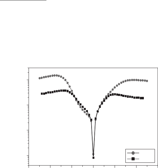
21.4.1.1 Spectral response
The spectral response of the QDIP was tested on a Fourier transform infrared (FTIR) spectrom-
eter. Photoresponse peaked at 6.4 μ m and had a cut-off at 6.72 μ m (see Fig. 21.14 ). The spectral
width ( Δ λ / λ
peak
) was 20%, indicating bound-to-bound intersubband absorption. The shape, peak
and cut-off of this QDIP showed negligible change with varying temperature (from T 7 7 K t o
T 120 K) and bias (from V
b
1 V t o V
b
1 V ) .
21.4.1.2 Dark current
The dark current of the QDIP was measured at 77 K using a closed cycle cryostat and the result
is shown in Fig. 21.15 . The dark current was still very high compared with QWIP and far from
CH021-I046325.indd 636CH021-I046325.indd 636 6/27/2008 5:48:08 PM6/27/2008 5:48:08 PM
Quantum Dot Infrared Photodetectors by Metal-Organic Chemical Vapour Deposition 637
200 nm n-InP top contact
layer grown at 590ⴗC
500 nm n-InP bottom
contact layer grown
at 590ⴗC
SI InP substrate
3 ML GaAs
InAs wetting layer
3 ML InGaAs
n-doped InAs QD
InP barrier
40 nm m
Ten periods
grown at 500ⴗC
Whole device structure Structure of one period
Figure 21.13 InAs/GaInAs/InP QDIP structure.
0
345678910
345678910
20
40
60
80
100
120
140
160
Bias dependent photoresponse at 77 K
Relative photoresponse (a.u.)
Wavelength (μm)
1 V
0.7 V
0.4 V
0 V
0.4 V
0.7 V
1 V
0
50
Temperature dependent relative photoresponse
77 K
100 K
120 K
Relative photoresponse (a.u.)
Wavelength (μm)
λ
peak
6.4 μm
Figure 21.14 Normalized relative spectral response curve for the ten stack InAs/GaInAs/InP QDIP.
6 4 20246
10
11
1 10
10
1 10
9
1 10
8
1 10
7
1 10
6
1 10
5
1 10
4
1 10
3
1 10
2
1 10
1
77 K
100 K
120 K
150 K
200 K
Temperature dark currents
Dark current (A)
Bias (V)
Figure 21.15 Dark current measured as a function of bias for the ten stack InAs/GaInAs/InP QDIP at different
temperatures.
CH021-I046325.indd 637CH021-I046325.indd 637 6/27/2008 5:48:09 PM6/27/2008 5:48:09 PM
638 Handbook of Self Assembled Semiconductor Nanostructures for Novel Devices in Photonics and Electronics
the predicted value. As will be shown next, this problem can be partly solved by using a current
blocking layer.
21.4.1.3 Responsivity
The absolute magnitude of the blackbody responsivity ( R
bb
) was determined by measuring the
photocurrent I
p
with a calibrated blackbody source which was set at 800°C. Test mesa was front
illuminated from the top of the mesa with normal incident infrared radiation. Peak responsivity
( R
p
), a more general merit for infrared detector, can be calculated as:
RR
Md
MRd
pbb
det
det
0
0
∞
∞
∫
∫
()
()()
λλ
λλλ
(21.32)
where R ( λ ) is the normalized photoresponse spectrum, and M
det
( λ ) is the blackbody exitance
spectrum, and the results at both 77 K and 100 K are shown in Fig. 21.16 . At T 77 K and a
bias of 1.7 V, a peak responsivity of 1.5 A/W was observed for our QDIP. The peak responsiv-
ity at 100 K did not change around from 1 V to 0.8 V, but at higher biases, the responsivity
decreased compared to that of 77 K.
3 2 10123
1
10
100
1000
77 K
100 K
Responsivity (mA/W)
Bias (V)
Figure 21.16 Responsivity measured as a function of bias for the ten stack InAs/GaInAs/InP QDIP at 77 K and
100 K.
21.4.1.4 Noise current
Noise current was measured and the result is shown in Fig. 21.17 . The noise current ( i
n
) was
measured at both T 77 K and T 100 K using a fast Fourier transform spectrum analyser. As
shown in Fig. 21.17 , very low noise was observed around 0 V at 77 K. Beyond these ranges, the
noise was dominated by generation–recombination noise of the dark current [20] . The noise cur-
rent increases very fast with increasing temperatures.
21.4.1.5 Detectivity
The specifi c detectivity was calculated based on the peak responsivity and noise current. The peak
detectivities ( D *) can be calculated from D * R
p
( A · Δ f )
1/2
/ i
n
, where A 1.375 1 0
3
c m
2
is
the illuminated detector area and Δ f 1 Hz is the bandwidth. The detectivities of our QDIP as a
function of bias at both T 77 K and T 100 K are shown in Fig. 21.18 . The highest detectivities
CH021-I046325.indd 638CH021-I046325.indd 638 6/27/2008 5:48:10 PM6/27/2008 5:48:10 PM