Higgins M.D. Quantitative textural measurement in igneous and metamorphic petrology
Подождите немного. Документ загружается.

2.5.2.2 X-ray maps: EMP, SEM and Micro-XRF
X-ray maps are images in which the intensity (pixel value) is related to the
composition of the surface. They are created from analysis of secondary
X-rays produced when electrons strike a surface with sufficient energy
(Reed, 1996). The energy (or wavelength) of some of these X-rays are char-
acteristic of the atomic number of the atoms in the target and hence can be
used to determine the elemental concentration. The quantity of X-rays prod-
uced per unit mass decreases considerably with atomic number, as does the
sensitivity of the detector and window systems.
All EMPs and most SEMs have the X-ray detectors needed to produce
X-ray maps. There are two types of X-ray detector. Energy-dispersive detec-
tors use a silicon or germanium crystal and can measure many different X-ray
energies simultaneously. Most are not sensitive to elements lighter than
sodium and the resolution is not always sufficient to separate adjacent peaks
produced by different elements. Wavelength-dispersive detectors use a crystal
to diffract the X-rays produced by the sample. The angle between the detector,
sample and the crystal is varied to select different X-ray wavelengths and hence
only one element can be measured at a time. The resolution and sensitivity of
this detector are greater than those of the energy-dispersive detectors and hence
they are more sensitive and precise.
If an electron beam is scanned (rastered) across a sample then the X-rays
emitted at each point can be filtered for each element. This can be assembled to
give an X-ray map of the sample for each element. For larger samples the beam
can remain stationary and the sample driven mechanically to give the same
effect. Such images overcome some of the problems associated with BSE
images, in that minerals such as quartz and feldspars are clearly distinguished.
However, production of X-ray maps is time-consuming and hence costly. In
addition, the resolution of the images is commonly poor compared to BSE
images as the X-rays are much less intense.
Secondary X-rays are also generated when a beam of primary X-rays strikes
a surface. This is called X-ray fluorescence (XRF) and is commonly used for
the chemical analysis of powder samples. Recent developments in X-ray optics
have enabled the beam size to be reduced to 50 or even 10 mm in a micro-XRF
instrument. While this resolution is much less than that of an SEM it is
sufficient for many studies. The X-rays are generally analysed with an
energy-dispersive detector, as for an SEM. There are many advantages to
this technique: the equipment is much cheaper and the analyses faster. It can
operate without a vacuum and there are no electronic charging effects, as
X-ray photons are neutral.
2.5 Surface and section analytical methods 19
2.5.2.3 Cathodoluminescence
Cathodoluminescence is the emission of light by a crystal in response to
electron bombardment (Pagel, 2000). This effect is only seen in some miner-
als, but these include such common species as feldspars, calcite, zircon and
quartz. The intensity and colour of the light are highly variable and com-
monly depend on the concentration of trace elements called activators and
the density of lattice defects. Hence, cathodoluminescence can be used to
distinguish grains or parts of grains with different growth histories. It is used
extensively to examine the petrology of sedimentary rocks, but has been less
exploited in textural studies of metamorphic and igneous rocks (e.g. Titkov
et al., 2002).
Cathodoluminescence is most commonly measured with a luminoscope: a
special instrument that is attached to a regular petrographic microscope. It can
also be observed with the optical system of an EMP. The most sensitive
method is to use a special light detector in an SEM, but this only records the
intensity and not the colour of the light.
2.5.2.4 Orientation contrast imaging
Under normal ‘flat scanning’ mode the mean atomic number of the crystal (
Z)
controls most of the variation in BSE intensity. However, if the electron beam
hits the sample obliquely then the crystallographic orientation of the crystal
becomes important because electrons are channelled into and out of the
crystals along lattice planes (Figure 2.4; Prior et al., 1999). If these are parallel
to the electron beam and/or direction of the detector the electron intensity will
be enhanced. This effect is exploited in orientation contrast imaging (OC). In
flat scanning the OC effect is about ten times less important than
Z effects.
However, if the sample is tilted at 708 to the beam direction then OC dominates
(Figure 2.4).
Surface preparation is particularly important in OC. Normal polishing
(sufficient for BSE images) disturbs the crystal lattice near to the surface and
inhibits the OC effect. Therefore, final polishing must be done using special
techniques, such as colloidal silica (Xie et al., 2003), chemical–mechanical
polishing or etching (Prior et al., 1999).
This method may be especially useful for imaging touching cubic (isometric)
crystals. Such minerals are optically isotropic and hence cannot be separated in
reflected and transmitted light. However, OC varies with the orientation of the
lattice planes; hence the crystals will have different intensities and grain
boundaries can be easily identified.
20 General analytical methods
2.5.3 Optical analytical methods
Examination of rocks in transmitted and reflected light has a long history and
still remains a very cost-effective analytical method. Indeed, it is probably the
most commonly used method in quantitative textural analysis. The wide range
in the optical properties of minerals, especially their common anisotropy,
makes it easy to distinguish individual crystals, even when they touch. Hence,
it is the method of choice for minerals that are especially abundant in a rock.
The quality of images is very important for successful quantification. Many
older microscopes have high-quality dedicated (and commonly antiquated)
film cameras. Individual photographs taken on 35 mm film can sometimes be
enlarged to 35 cm without loss of resolution. The prints can then be scanned
for digital processing. Small ‘domestic’ digital cameras commonly have com-
plex zoom lenses which can have considerable flare and chromatic aberration.
More expensive dedicated digital cameras have much simpler and better lenses
and greater resolution.
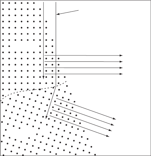
Electron
beam
Channelled
electron
beams
Crystal 1
Crystal 2
Figure 2.4 Orientation contrast imaging. The lattices of two crystals with
different orientations are indicated by the arrays of points. In this example
the electron beam is vertical and the sample surface is at an angle of about
70 degrees. Electrons are channelled into and out of the crystals along
lattice planes.
2.5 Surface and section analytical methods 21
2.5.3.1 Transmitted light
Rocks are examined in transmitted light using thin sections. A standard thin
section is 30 mm thick and measures 23 cm. Larger thin sections, 3 7 cm, are
also readily available, as are thinner-than-normal sections. Polished thin sec-
tions that can also be used in reflected light are generally only available in the
smaller size. Identification of minerals by optical methods is complex and is
covered by basic texts, such as Nesse (1986).
Thin sections are usually examined in plane-polarised light and under
crossed polarisers with a petrographic microscope. Normal petrographic
microscopes equipped with film or digital cameras can yield good photographs
of regions up to 2 mm. Unusual low-power objectives (1) can image larger
areas, but special stages are needed and illumination is commonly uneven.
Larger images can be assembled by taping together photographic prints into a
mosaic or by electronically stitching digital images (see Appendix).
It is difficult to get an image of a whole thin section with a regular petro-
graphic microscope. Some specialised zoom microscopes can cover a whole
regular thin section with as few as 10 images. Other solutions found are a film
scanner (Tarquini & Armienti, 2001), a slide-copying apparatus or camera
attachment, or a light bench. Some systems use a flash so that vibration
problems are reduced. It is also possible to use a document scanner that can
operate with transmitted light on a thin section. This works well for a direct
image or with plane-polarised light produced by a single Polaroid sheet.
However, if two Polaroid sheets are sandwiched on either side of the section
to make a cross-polarised image then there is not always enough light to yield a
good image.
The lower limit of resolution is commonly close to the thickness of the
section, 30 mm. Although the physics of light indicates that a higher resolution
is possible, it is rarely approached in most studies because of the difficulty of
observing small crystals in thin section, except where the matrix is lightly
coloured. It should also be remembered that small crystals enclosed in the
thin section are seen in projection whereas larger crystals are seen in section.
This necessitates different mathematical procedures to calculate the 3-D
textural parameters (see Chapter 3).
A multitude of colour images are possible from a single thin section: in
plane-polarised light pleochroic minerals will have different colours according
to the orientations of the polarisers. Similarly, when examined with crossed
polarisers crystals will show different colours and extinctions according to
the orientation of the polarisers. Most types of automatic image analysis
cannot cope with more than a single image, however, computer-integrated
22 General analytical methods
polarisation microscopy methods are designed to exploit this aspect of optical
mineralogy (see Section 2.6.4; Heilbronner & Pauli, 1993, Fueten, 1997).
In cross-polarised light some crystals will generally be in extinction for any
orientation of the section. This can be a problem for the measurement of
crystals using simple observations of a single cross-polarised image. A little-
used optical technique, the ‘Benford plate’ can eliminate this problem (Craig,
1961). The name is a misnomer as the set-up consists of two matched quarter
wave plates (retardation ¼ 132 nm). One is placed below the thin section,
oriented at 908 to an accessory plate holder. The other is inserted in the normal
position for an accessory plate. With the Benford plates installed, the birefrin-
gent colour of crystals is identical to that seen at the 458 position without the
plates. However, the birefringence colour, and its intensity, do not change with
rotation of the stage; that is, extinction no longer occurs. Clearly, this can be
very useful as all crystals can be observed with the stage in a single orientation.
However, the intensity contrast between grains may be less than that normally
observed. This image is identical to the maximum birefringent image obtained
in computer-integrated polarisation microscopy (see Section 2.6.4).
Thin sections are generally observed orthogonal to the plane of the section,
but in some situations it may be useful to remove this constraint. The universal
stage is an accessory for a standard petrographic microscope that enables
tilting of the section with respect to the direction of observation. Hence,
crystals and their boundaries can be examined from different orientations. It
is described in more detail in Section 5.5.1.
The infrared absorption of mineral sections can also be examined, generally
by using a high resolution infrared spectrometer (e.g. Ihinger & Zink, 2000).
A section thicker than normal (800 mm) is polished on both sides and the
spectra of 100 mm spots collected. Each spectrum is filtered for absorbance in
a range of wavelengths that correspond to resonance of specific chemical
entities and is used to build an absorbance map of the section. This technique
has been used to examine the distribution of hydrogen in quartz.
2.5.3.2 Reflected light
Rocks are examined in reflected light using polished thin sections or blocks
(Cabri & Vaughan, 1998). Examination of polished sections in orthogonally
reflected light can complement studies in transmitted light or be done inde-
pendently. Many research microscopes are set up so that they can be used for
both optical techniques. The variation in optical properties in reflected light
is generally more limited than that in transmitted light, but the method is
especially important for opaque minerals. The resolution of the method is not
limited by scattering of light within the material and hence features as small as
2.5 Surface and section analytical methods 23
1 mm can be readily observed. However, there is no good way to get images of
areas larger than can be viewed with the normal microscope lenses or
assembled from image mosaics. For instance, a document scanner does not
yield very good images because the light is not orthogonal to the surface.
However, it may be useful if there are very large differences in reflectivity.
Although surfaces may be viewed in both plane-polarised light and under
crossed polarisers, the former is used most commonly for imaging surfaces. As
for transmitted light, anisotropic minerals may have different reflectances
(colours) for different orientations, but the effect is not large for most miner-
als. Hence, minerals are usually imaged in plane-polarised or unpolarised
light. In this situation the most important parameter is the reflectance of the
mineral. Reflectances have been recently tabulated for all new minerals, at
20 nm intervals from 400 to 700 nm, but values at four standard wavelengths
are generally used (470, 546, 589 and 650 nm). Most transparent minerals, such
as quartz and feldspars have reflectances in the range 5–10%. Other minerals
are much higher: oxide minerals 12–30%; sulphides 12–60% and metals
50–100%. Surfaces may also be etched or stained to bring out the contrast
between different minerals, sub-grain boundaries and crystal defects (see
Section 2.5.3.3 and review by Wegner & Christie, 1985 ).
Minerals can be imaged electronically by standard charge-coupled device
(CCD) cameras. However, such cameras are designed to mimic the human eye
and hence record light in three wide spectral bands. A better approach is to use
narrow (10 nm) bandwidth filters (Pirard, 2004). Such a system needs to be
carefully calibrated, but can give much better resolution of mineral phases,
especially those with reflectances greater than 5%. This method can distin-
guish mineral pairs that are problematic in BSE (e.g. chalcopyrite/pentlandite)
or X-ray maps alone (e.g. hematite/magnetite/goethite).
2.5.3.3 Nomarski (DIC) microscopy
A very useful optical technique for imaging surfaces is differential interference
contrast (DIC) or Nomarski microscopy. It has long been used by metallur-
gists to produce detailed images of polished surfaces, and has also been used by
petrologists to examine mineral and rock textures (Anderson, 1983, Pearce
et al., 1987, Pearce & Clark, 1989). It can reveal both the exterior shape of
crystals and their internal structure, and can be useful for distinguishing
crystals from a glassy matrix. It can be applied to thin sections and hence is
complementary to normal reflected and transmitted light methods.
Nomarski microscopy is an optical technique for imaging the micro-relief of
surfaces (<0.5 mm). A light beam is split by a prism; one beam is reflected off
the surface and allowed to interfere with the reference beam. Hence the method
24 General analytical methods

is sensitive to surface relief of the order of the wavelength of light. The special
lenses and prisms that are needed are usually fitted to a specialised microscope,
which may be available in metallurgy laboratories.
The initial surface must be very well polished, with no remaining scratches.
This can be done in the same way as for normal polished sections. The surface
is then etched to develop relief (Table 2.2; Wegner & Christie, 1985). Etch
depth will depend on the nature of the mineral, the orientation of the section
and the density of crystalline defects. Finally, the surface may be coated with
carbon or metal using the same apparatus that is used for SEM studies. This
coating reduces interference from reflections beneath the surface of the
sample. However, it also reduces the contrast in reflectivity between different
minerals and glass. If polished thin sections are used then the technique may be
complemented by examination with transmitted light, if the coating is not too
thick. This is useful if two anisotropic crystals touch; they may then be
distinguished by differences in optical orientation.
2.5.4 Slabs and outcrops
For rocks containing large crystals sawn slabs can be very useful. The
surface should be planar, but it is not usually necessary to have a perfectly
polished surface, unless very small crystals will be examined. A sawn surface
can be ground flat with wet abrasives on a rotating lap (wheel) or with
waterproof (wet and dry) silicon carbide/oxide paper on a flat surface such
as a sheet of glass.
The surface can be etched or stained to enhance the contrast between the
different minerals. One of the best known stains is sodium cobaltinitrite which
Table 2.2 Etchants used for Nomarski examination of minerals. All samples
should be neutralised with Na
2
CO
3
after etching so that degassing of HF does not
etch the objective lenses. A much longer list of possible etchants and further
details of the methods are available in Wegner and Christie (1985).
Mineral Etchant Notes and reference
Plagioclase Fluoroboric acid (HBF
4
); 2–3
minutes at room temperature
(Anderson, 1983)
Olivine Concentrated HCl; 10–20 minutes
at 45 8C
(Clark et al., 1986)
Clinopyroxene Concentrated HF; 2–4 minutes
at room temperature
HF attacks plagioclase and
olivine vigorously (Clark
et al., 1986)
2.5 Surface and section analytical methods 25

colours all potassium feldspar a deep orange. Other minerals can also be
stained (Table 2.3; Hutchison, 1974). It is also possible to stain thin sections.
Crystals in slabs can be measured manually in several ways: (1) The simplest
is with a ruler and protractor (see below). (2) Mineral outlines can be traced
onto a transparent overlay and subsequently scanned and analysed automat-
ically. (3) Slabs can be placed on a document scanner and the images analysed
automatically or manually. Very large polished rock panels, as used for build-
ing facing, can provide material transitional in scale between slabs and
outcrops.
Very large crystals must be examined in outcrop, especially those with low
number densities. Crystals can be measured directly with a ruler and protrac-
tor. Photographs of outcrops can also be used, but not generally so success-
fully – what is clear in the field can be confusing on a photograph at a later
date. The method is most easily applied to flat surfaces naturally polished by
glacial action (Higgins, 1999). However, it can also be used on surfaces
smoothed by rivers or the sea. In some cases dimensional stone quarries may
yield sufficiently smooth surfaces.
2.6 Extraction of textural parameters from images
Some of the analytical methods described above yield quantitative textural
data directly. However, most produce images that must be measured to extract
various textural parameters. Manual image analysis methods demand a large
amount of individual attention and judgement and user training is very
important. Such methods generally yield high-quality data directly, but are
Table 2.3 Some staining procedures that can be used to help distinguish
minerals in slabs. Some of these techniques can also be used for staining thin
sections. Details of these and other procedures can be found in Hutchison (1974).
Minerals Treatment Colours and not es
K-feldspar 1) HF (49%) 30 seconds
2) Na
3
Co(NO
2
)
6
Sodium
cobaltinitrite (freshly
prepared) 10 seconds
K-feldspar ¼ oran ge
Plagioclase ¼ white
Quartz ¼ grey
Quite resistant to abrasion
Plagioclase Amaranth red Red. Easily removed from surface
Calcite and
dolomite
1) HCl (1.5%) 10 seconds
2) Alizarin red
3) Potassium ferrocyanide
K
4
Fe(CN)
6
3H
2
O
Calcite ¼ rose to red
Dolomite ¼ colourless
26 General analytical methods
very time-consuming. In addition, there is always the possibility of operator
bias, especially where the researcher does the measurement. Automatic image
analysis methods may take much time to set up, but can be faster if many,
similar samples need to be processed (see the general review in Russ, 1999).
The quality of the data is commonly not as high as that produced manually,
even though it may suffer less from operator bias. This may be balanced by a
greater number of crystals and samples measured.
The images produced by many analytical methods have too few pixels for
adequate precision. Several images can be combined together like a mosaic to
produce a larger image. This can be done electronically or by taping photo-
graphic prints together and scanning the mosaic.
2.6.1 Size limits of measurements
No matter what method is used to acquire quantitative textural data, the mini-
mum size of crystal that can be recognised and measured must be established. If
no data are listed for crystals smaller than a certain size it is important to indicate
if this reflects an artefact of measurement or a real lack of crystals in that size
range. Methods can be combined to cover a wider size range than would be
possible with a single method. For instance data from outcrop measurements can
be combined with data from slabs; thin sections can be measured at two different
scales; BSE images can be combined with thin section measurements. It is very
important to record and publish the details of the data-acquisition method and
steps taken to ensure adequate quality control.
The maximum size of crystal that can be precisely determined is generally
determined by the number of crystals in the largest interval, and not by the
physical limitations of the method. However, the maximum size must also be
specified where possible.
2.6.2 Manual image analysis
Crystals viewed with an optical microscope can be measured directly without
recording an image: the scale in the microscope eyepiece can be used to
measure intersection length and width, and the crystal rotated on the stage
to determine the orientation. This has the advantage that different magnifica-
tions and orientations of the stage can be used to identify the crystal; hence a
wide range of crystal sizes can be measured. It is also useful for rocks that have
a low number of crystals per unit volume (number density). However, it is
difficult to keep track of which crystals have been measured, and the use of a
photograph is advised, even if only to check off that a crystal has been
2.6 Extraction of textural parameters from images 27
measured. A similar method can be used with an electron microscope (SEM),
with the same caveats.
Most of the techniques discussed above produce images: single images or
mosaics, on paper or in electronic form. These images can then be measured
manually in several different ways: (1) the intersection length, intersection
width, long-axis orientation and centroid position can be determined using a
ruler and protractor; (2) the crystal outlines may be traced onto a transparent
overlay, which is then scanned and analysed automatically as discussed below;
(3) digital images can be imported into a vector drawing program (e.g.
CorelDraw
TM
) and the crystal outlines traced by drawing a polygon with the
mouse; (4) photographs can be put on a digitising tablet and the outline of each
crystal in the photograph traced using the digitising puck. A number of
programs can be used to control the digitising tablet (see Appendix) and
reduce the raw positional data to textural parameters. In each case the actual
outline of the crystal in the thin section should be verified with a polarising
microscope.
2.6.3 Automatic image analysis
Automatic image analysis commonly involves many different steps
(Figure 2.5). The goal of image processing is to segment the original image
into a classified image of the mineral of interest: a wide range in pixel values in
one or many channels of the original data image are reduced to a small number
of different pixel values, one for each phase of interest. Clearly, it may not be
easy to classify some pixels. This commonly occurs where a pixel traverses the
contact between two minerals. Sub-pixel grains and unknown minerals can
also cause problems. It must be decided if it is really necessary to classify all
pixels or if unclassified pixels can be accepted.
A number of successful image processing procedures have been published
but many are specific to particular proprietary image processing software (e.g.
Perring et al., 2004). The expense and limited distribution of these systems has
led many researchers to use general purpose image software (i.e. Adobe
Photoshop
TM
) and powerful open-source, free software (e.g. NIHImage/
ImageJ). Here, I have tried to present an approach that can be applied more
generally. I do not want to enter into the specifics of program usage, as this will
be outmoded before the book is published.
2.6.3.1 Grey-scale images
Some analytical methods produce images with a single variable, usually called
grey-scale images: for instance, the amount of backscattered electrons or the
28 General analytical methods