Kothari D.P., Nagrath I.J. Modern Power Systems Analysis
Подождите немного. Документ загружается.

164
I
toctern
power
Svstem
,Analvsis
Power
factor
ar
station
2
=
coS
(ron*r
15'638
')
=
O.zgs
lagging
\20)
The
station
loads,
load
demands,
and
line
flows
are shown
in Fig.5.1g(b).
ir-;-
t {
iz i, r"
r
p
""
rt
"
"r
v.
Case
(b):
Cable impedance
=
0.005
+70.05
=
0.0502
lB4.3 pu.
In rhis
case
the
cable
resistance
causes
real power
loss
which
is not
known
a
priori.
The real
load
flow
is thus
not obvious
as was
in
the case
of
R
=
0. we
specify
the
generation
at
station
I as
Pcr=
20
Pu
The
consideration
for fixing
this
generation
is
economic
as we
shall see in
Chapter
7.
The
generation
at
station
2 will
be
20
pu
plus
the cable
loss.
The
unknown
variables
in
the problem
are
P62,
6p
Qcp
Qcz
characteristics
and
Performance
of
power
Transmission
Lines
165
6r
=
14.4"
Substituting
dr in
Eqs.
(ii),
(iii)
and
(iv),
we
ger
Qct=
5.13,
Qc2
=
16.12,
PGz
=
20.10
It may
be
noted
that
the
real
Gz(Pcz
-
20.10).
^'- - ^D'
"'^'
power
loss
of
0. i pu
is
supplied
by
The above
presented
problem
is
a two-bus
load
flow problem.
Explicit
solution
is always possible
in
a two-bus
case.
The
reader
should
try
the
case
when
Qcz=710
and
lV2l
='-
The
general
load
flow
problem
will be taken
up in
Chapter
6. It will
be
seen
that
explicit
solution
is not
possible
in the
general
case
and
iterative
techniques
have
to be resorted
to.
A 275
kV transmission
line
has the
following
line
constants:
A
=
0.85
15":
B
-
200
175"
(a)
Determine
the
power
at unity power
factor
that
can
be
received
if the
voltage
profile
at each
end
is to
be
maintaine
d
at 275
ky
.
\
(b)
What type and
rating
of compensation
equipment
would
be required
if the
load is 150
MW
at unity power
factor
with
the
same
voltage
profile
as
in
part
(a).
(c)
With
the load
as in
part (b),
what
r,vould
bc
thc
receiving-end
voltage
if
the
compensation
equipment
is
not
installed?
Solution
(a)
Given
lV5l
=
lVal
=
215
kY;
e,
=
5o,
C
=
J5".
Since
the
power
is received
at
unity power
factor,
Qn=
o
Substituting
these
values
in Eq.
(5.62),
we can
write
Let
us
now
examine
as to
how
many
system
equations
can
be formed.
From
Eqs.
(5.68)
and
(5.69)
Pct
-
Por
=
',
=
#cos
d-
V#*s@+
61)
5
=
-=
cos
84.3"
-
^-=
cos
(84.3"
+
4)
(i)
U.U)UZ
U.U)UZ
ecr-
eot=
es=
ffrt^t-trr,\i,sin
(d+
4)
Qcr
-
S
=
;j-
sin 84.3"
-
=+-sin
(84.3"
*
Ur)
(ii)
0.0502
0.0502
From
Eqs.
(5.66)
and
(5.67)
Poz-P
-P
-lvtllvzl
lv'P
Gz=
Pn=
-ff
cos
(d-
6r)-
-1:-cose
2s
-
Pc2=
*;rcos
(84.3"
-
A,l
-
#rcos
84.3o
(iii)
eor-
ecz=
en=
Uffiri,
(o-
6t>
-
,Yl!rr",
lzl
15
-
Qcz=
#,
sin
(84.3"
-
4)
#,
sin
84.3"
(v)
Thus
we
have four
equations,
Eqs.
(i)
to
(iv),
in
four unknowns
p52,
51,
e61,
Q62.Even
though
these
are
non-linear
algebraic
equations,
solution
is
possible
in
this
case.
Solving
Eq.
(i)
for
d,, we
have
o
-
!5x]75-
sin
(75"-
d)
-
200
0=378sin(75"-A-302
which gives
6- ))"
From
Eq.
(5.61)
ij;
x
Q75)2
sin
(75"-
5")
Pn=
275^x275
cos
(75o
-
22")
-
9
85
*
(2712
cos
70o
"
200
200
-
227.6
-
109.9
=
117.7
D{W
150=
215zq7cos
(75o
-
5)-
200
150=
378
cos
(75"
-
4
-
110
or
5
=
28.46"
From
Eq.
(5.62)
166
|
todern
power
Svstem
Analvsis
I
(b)
Now
lV5l
=
lVpl
=
275
kV
Power
dernanded
by
load
=
150
MW
at
UPF
Pn=
PR=150MW;
Qo=0
0
=
!:y-*t
sin
(75'-
.5)
-
*tvot2
sin
70' (ii)
200
200
From
Eq.
(ii),
we get
sin(75"-
A=0.00291VR1
characteristics
and
Performance
of Power
Transmission
Lines
Ifil
150
=
1.375
lynt
(1
_
(0.002912
lv^121u2
_
0.00l45tyRl2
Solving the
quadratic
and
retaining
the
higher value
of lv^|,
we
obtain
lVal
=
244.9
kV
Note:
The
second
and lower
value
solution
of
lVol
though
feasible,
is
impractical
as it corresponds
to
abnormally
low
voltage
and
efficiency.
It is
to be observed
from
the results
of this problem
that
larger power
can
be
transmitted
over a
line with
a
fixed
voltage profile
by
installing
compensation
equipment
at
the receiving-end
capable
of feeding
positive
VARs
into
the line.
Circle Diagrams
It has
been shown
above
that-the
flow
of
active
and
reactive
power
over
a
transmission
line can
be handled
computationally.
It will
now
be shown
that
the
Iocus of
complex
sending-
and
receiving-end
power
is
a circle.
Since
circles
are
convenient
to draw,
the circle
diagrams
are
a useful
aid
to visualize
the load
flow problem
over
a single
transmission.
The
expressions
for
complex
number
receiving-
and
sending-end
powers
are
reproduced
below
from
Eqs.
(5.58)
and
(5.59).
0.85
.^- -,)
,*
x
(275)'cos
70o
en=
"#
sin
(75.
-
28.46")
-
0'85
x
e75)2
sin
70o
200
-
274.46
-
302
=
-
2l.56
MVAR
Thus
in
order to
maintain2T5
kV
at a
receiving-end,
en=
-27.56
MVAR
must
be
drawn
along
with
the real
power
of Po
=
150
MW.
The
load
being
150 MW
at
unity
power
factor,
i.e.
Qo
=
0,
compensation
equipment
must
be installed
at the
receiving-end.
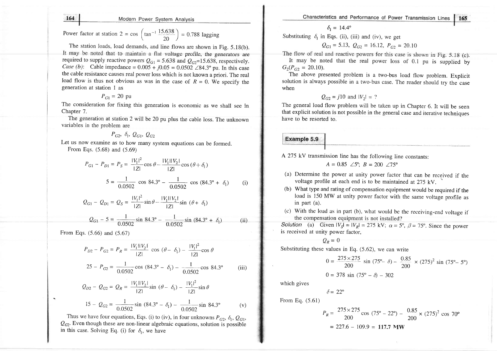
With
reference
to Fig.
5.19, we
have
-27.56+
Qc=0
or
Qc
=
+ 27.56
MVAR
i.e.
the
compensation
equipment
nnust
feed
positive
VARs into
the
line.
See
subsection
5.10 for
a
more detailed
explanation.
150
-
j27.56
150
+/0
sR=-
lfl
rv^r'
4/r-
r.
+P
4r-
b)
n=
l+l
vs(
t(r-
o)-
+3
4/r+
o
(s.s8)
(5.5e)
(s.16)
Fig.
5.19
(c)
Since no
compensation
equipment
is
provided
Pn=
150MW,
Qn=0
Now,
The units
for
Sp
and
S, are
MVA
(three-pha,se)
with
voltages
in
KV line.
As
per
the above
equations,
So
and
,9,
are
each
composed
of two phasor
componenfs-6ne
a constant
phasor
and
the
other
a
phasor
of
fixed
magnitude
but variable
angle. The
loci lor
S^ and
S, would,
therefore,
be
circles
drawn
from
the tip
of constant phasors
as centres.
It follows
from
Eq.
(5.58)
that
the
centre
of receiving-end
circle
is
located
at the tip
of the.phasor.
lV5
l= 275kV,lVal=
?
Substituting
this data
in
Eqs.
(5.61)
and
(5.62),
we have
150
=
t':\!'"os
(75"
-
A
-
ggtv^t2
cos
70"
200
200
-l+l
vRP
t(r
-
a)
I Bl
'\
in
polar
coordinates
or in
terms
of rectangular
coordinates,
Horizontal
coordinate
of the centre
(i)
=
-l|lrv-f
cos
(//-
a)
MW
(s.77)
e.-'1,,
,
.
I
.d6Eif
_
Modern
power
System
Analysis
.,.,,
Vertical
coordinate
of the
centre
=
-i{-ltv*t2
sin
(tJ-
a)
MVAR
lBl
The
radius
of
the
receiving-end
circle
is
tysllyRlMVA
tBl
lAll t2
lall
u"l
Reference
line
for
angle
6
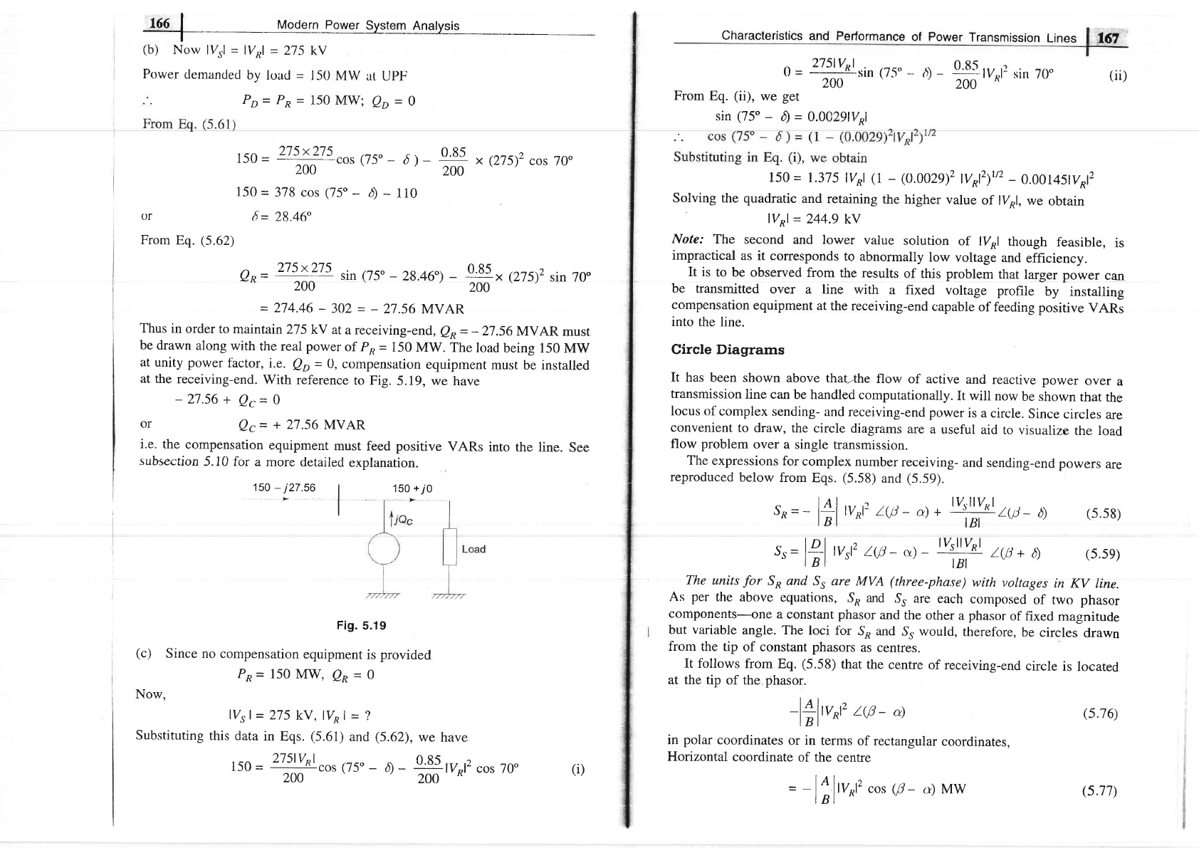
Fig.
5.20
Receiving-end
circle
diagram
F'or
constant
lVol,
the
centre
Co
rernains
fixed
and
concentric
circles
result
for
varying
l7rl.
However,
for
the
case
of
constant
ll{l
and
varying
lvol
the
centrcs
o1'circles
movc
along
the
line
OCoaru),have
raclii
in accordance
to
ltzrl
lvRtABt.
Similarly,
it follows
from
Eq.
(5.59)
that
the
centre
of
the
sending-end
circle
is
located
at
the
tip
of
the phasor
characteristics
and
performance
of
power
Transmission
Lines
t69
Vertical
coordinate
of
the
centre
=
l+ilvrt2
sin
(F
-
a)
MVAR
t
Bt
The
radius
of
the
sending-end
circle
is
(5.78)
(s.81)
The
sending-end
circle
diagram
is
shown
in
Fig.
5.2I.Thecenrre
is
located
by
drawing
OC,
at
angle
rt?
-
a)
from
the
positive
MW-axis.
From
the
centre
the
sending-end
circle
is
drawn
with
a
.uoi.rr${e(same
as
in
the
case
of
lBt
\
receiving-end).
The
operating
point
N
is
located
by
measuring
the
torque
angle
d(as
read
from
the
recefving-end
circle
diagram)
in
ttre
direction
indicated
from
thc
re'fi'rcncc'
Iinc.
l4l,u,,'
t(0.-
a)
I
Bl
in
the polar
coordinates
or
in
terms
of
rectangular
coordinales.
Horizontal
coordinate
of
the
centre
C5
Roforonco
lino
-
for
angle
d
Radius
lYsllVnl
lBl
Phasor
55
=
P5
+ie5
1--
Qs
+
Fig.
5.21
Sending-end
circle
diagram
i,i,=',!"i
=u':;=o
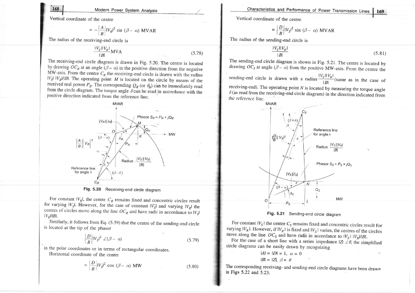
The
corresponding
receiving-
and
sending-end
circle
diagrams
have
been
clrawn
in
Figs
5.22 and
5.23.
(s.7e)
MVAR MVAR
=
B-ltv;2
cos
(f
-
a)
Mw
(s.80)
Pa=
oK
Qn= KM
Fig.5-22
Receiving-end
circre
diagram
for
a
short
rine
MVAR
Ps=oL
Qs=LN
L
Fig.
5.23
Sending-end
circle
diagram
for
a
stror.t
line
oJl:
use
of
circle
diagrams
is
i$ustrated
by
means
of
the
rwo
examples
given
A
50
Hz,
three-phasg,
275
kY,400
km
transmission
line
has
the
following
parameters:
characteristics and Performance
of
power
Transmission
Lines
[giM
t-
Resistance
=
0.035 Olkm
per
phase
Inductance
=
1.1
mHlkm
per
phase
Capacitance
=
0.012
pFlkm
per
phase
If
the line
is supplied
at 275 kV,
determine
the
MVA rating
of a
shunt
the receiving-end
when
the
line is delivering
no load.
Use
nominal-
zr
method.
Solution
R=0.035x400=14Q
X
=
314
x
1.1
x
l0-3
x
400
=
138.2
O
Z
=
14 +
7138
-
138.1
184.2"
Q
Y=
314
x
0.012
x
10-6
x
400
lg0"
-
1.507
x
10-3
/_W
U
A=
(t+Lvz\
=
1 +
-l-
x
t
.507 x
10-3
x
r3g.i
lri4.z"
\2)2
=
(0.896
+
70.0106)
=
0.896
lj.l'
B=Z-138.7
184.2"
lV5
|
=
275 kV,
lVpl
=
275 kV
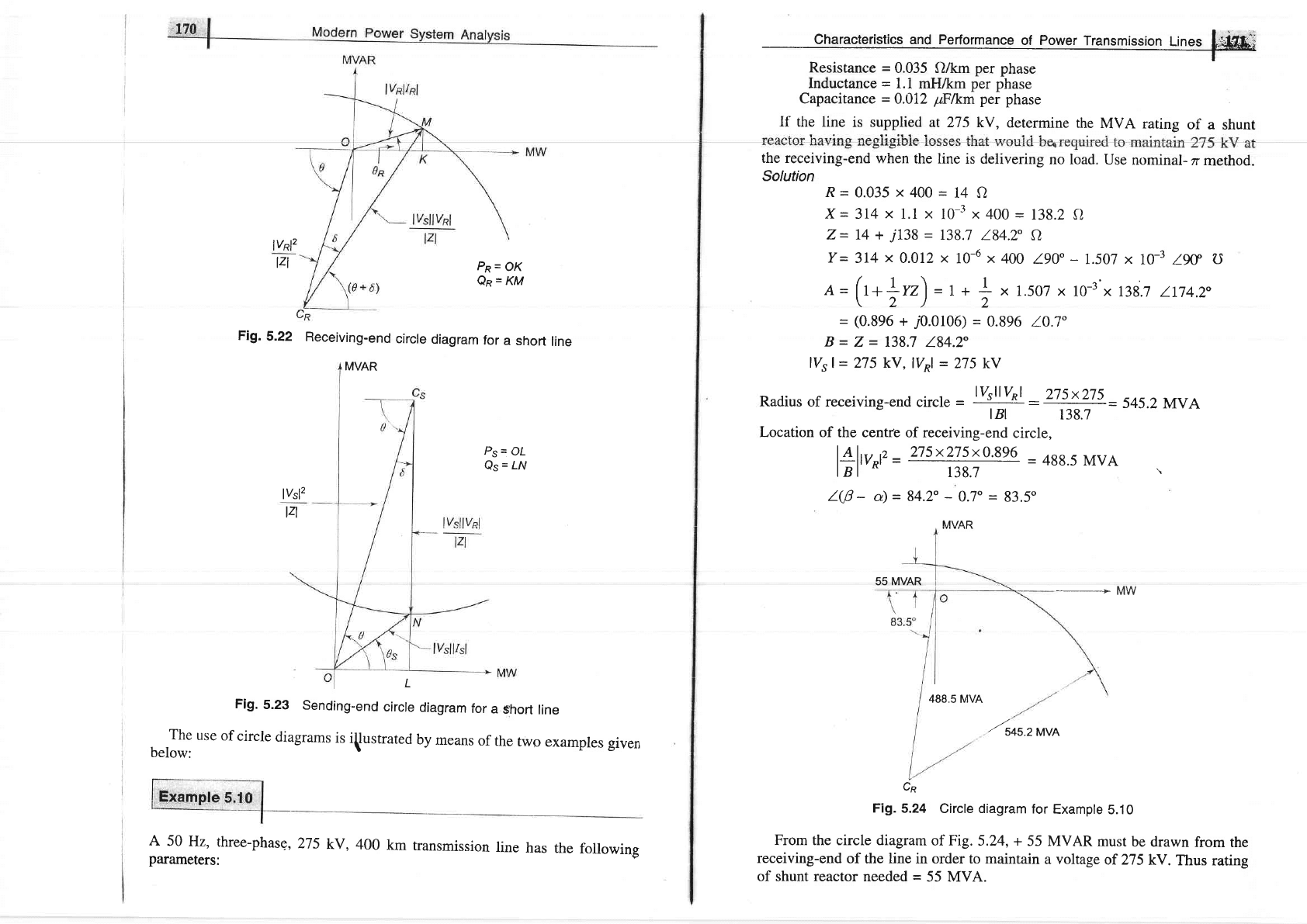
Radius
of receiving-end
circle
-
lysllyRl
-275x275
-
545.2MVA
tBl
138.7
Location of
the cenre of receiving-end
circle,
l4:l1
,,
275x275x0.896
=
488.5
MVA
I B I
ill
=
138J
=
'rdd')
rll
\
l@
-
a)
=
84.2"
-
0.7"
=
83.5"
i,\/A P
_
>MW
488.5
MVA
.tuou.rrro
Cp
Fi1.5.24
Circle diagram
for
Example
5.10
From the circle diagram
of Fig.
5.24, +
55 MVAR
must
be
drawn
from
the
receiving-end
of
the
line
in order to maintain
a voltage
of 275
kV.
Thus
rating
of
shunt
reactor
needed
=
55 MVA.
lvnl2
tzl
lvsl2
lzl
55 MVAR
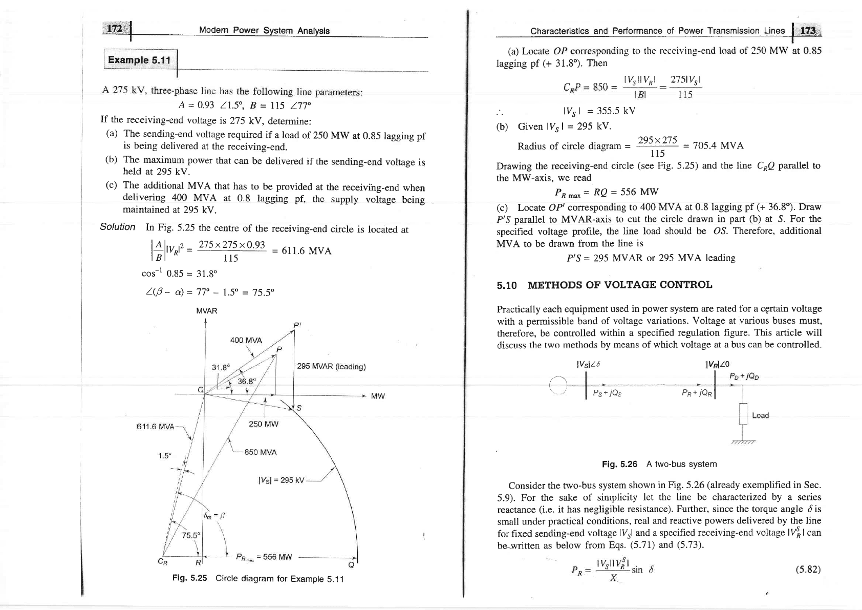
Example
5.11
X12,:jl
Modern
power
System
Analysis
A
-
0.93
11.5",
B
=
Il5
ll7"
If the
receiving-end
voltage
is
2'r-5
kV,
determine:
(a)
The
sending-end
voltage
required
if
a load
of 250
MW
at
0.g5 lagging
pf
is
being
delivered
at the
receiving-end.
(b)
The
maximum
power
that
can
be delivered
if the
sending-end
voltage
is
held
at 295
kV.
(c)
The
additional
MVA
that
has to
be provided
at the
receivihg-end
when
delivering
400
MVA
at
0.8 lagging
pt
the
suppty
voltage
being
maintained
at 295
kV.
Solution
In Fig.
5.25 the
centre
of the receiving-end
circle
is
located
at
l4li
t'
-
2t5x275x0'93
-
611.6
MVA
lBl
R'
-
tt5
cos-l
0.85
=
31.8"
l@-
a)=77o
-
1.5"
=
75.5"
Characteristics
and Performance
of
Power
Transmission
Lines
|
,i?3-;-
t-
(a)
Locate OP
conesponding
to the receiving-end load of
250 MW
at 0.85
lagging
pf
(+
31.8).
Then
, ^ or^
lysllyRl
275lvsl
lVsl
=
355.5
kV
(b)
Given
lV5 |
=
295
kV.
Radius
of
circle diagram
-
t".l?"
-
705.4 MVA
115
Drawing
the receiving-end
circle
(see
Fig.
5.25)
and the line C^Q
parallel
to
the
MW-axis,
we
read
PR-o
=
RQ
=
556
MW
(c)
Locate OPt
conesponding
to
400 MVA at 0.8 lagging
pf
(+
36.8"). Draw
P/S
parallel
to
MVAR-axis
to
cut the circle drawn
in
part
(b)
at S. For the
specified
voltage
profile, the line
load should be O^S.
Therefore, additional
MVA to be
drawn
from
the line
is
P/S
=
295 MVAR
or 295 MVA leading
5.10
METHODS
OF
VOLTAGE CONTROL
Practically
each equipment
used in
power
system are rated for a cprtain
voltage
with a
permissible band
of
voltage
variations. Voltage
at
various buses
must,
therefore,
be
controlled
within a specified
regulation figure. This
article will
discuss
the two
methods
by means of
whieh voltage
at a
bus
can be controlled.
lvslt6 lvRltj
MVAR
I
a)
I
p"-.io,
P^
iio*
|
Fig. 5.26
A two-bus system
Consider
the two-bus
system
shown
in Fig. 5.26
(akeady
exemplified in Sec.
5.9).
For
the
sake of
simplicity
let
the line be characterized by a series
reactance
(i.e.
it has
negligible
resistance). Further,
since the torque
angle d is
small
under
practical conditions,
real
and reactive
powers
delivered by
the line
for fixed
sending-end
voltage
lVrl
and a specified
receiving-encl
voltage
l{ | can
be-written
as
below
from
Eqs.
(5.71)
and
(5.73).
Fig.
5.25
Circle
diagram
for
Example
S.11
(5.82)
ef,
=
'li,
,,
u,
r
-
r v,i
rl
'X
Equation
(5.83)
upon
quadratic
solution*
can
also
be
written
as
rr{
r
=
}vrt
.
+tys
|
(1
-
4xesn
Avrtzlt/z
Since
the
real
power
demanded
by
the
loacl
must
be
delivered
by
the
line,
Pn=
Po
varying
real
power
demand
p,
is
met
by
consequent
changes
in
the
rorque
angle
d.
It
is,
however'
-to
be
noted
that
the
received
reactive
power
of
the
line
must
remain
fixed
at
esn
as given
by
Eq.
(5.g3)
for
fixed
rv,
I
and
specified
r4r.
il"
line
would,
therefore,
operate
with
specified
receiving-end
voltage
for
only
one
value
of
Qo
given
by
Qo
=
Qsn
Practical
loads
are
generally
lagging
in
nature
and
are
such
that
the
vAR
demand
Qn
may
exceed
et*.rt
easily
follows
from
Eq.
(5.g3)
that
for
or;
ot-
the
receiving-end
voltage
must
change
from
the
specified
value
'n'i
some
value
lTol
to
meet
the
demanded
VARs.
Thus
Q^=
o^=
lv*l
'
'Jo=
Qn
=
;i
(lYsl
-
lVol)
for
(QD>
QsR)
The
modified
lVol
is
then
given
by
rvlql
=
lvrt
-
+ty3
(1
-
4xeRltvrt
)r,,
nsmtssion
Lines
l"ffie
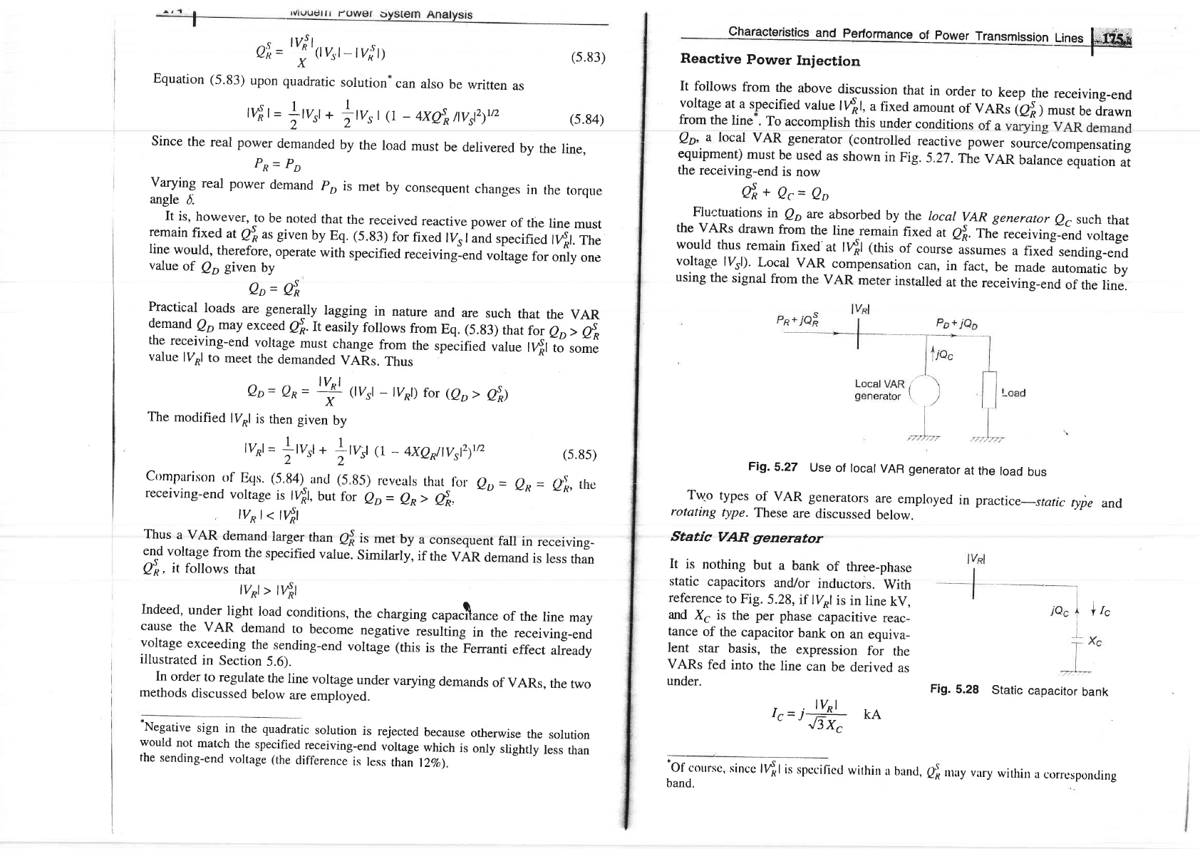
Reactive
Power
Injection
(5.83)
(5.84)
(s.85)
It follows
from
the
above
discussion
that
in
order
to
keep
the
receiving-end
voltage
at
a specified
value
l{1,
a
fixed
amount
of
VARs
tai
I
*;;;
drawn
Qn,
a
local
VAR
generator
(controlled
reactive
power
source/compensating
equipment)
must
be
used
as
shown
in
Fig.
5.27.
fle
vAR
balance
equation
at
from
the
line-.
To
accomplish
this
under
conditions
the
receiving-end
is
now
Oi
*
Qc=
Qo
Fluctuations
in
Qo
ue
absorbed
by the
local
vAR
generator
o6
such
that
the
vARs
drawn
from
the
line
remain
fixed
at
esn.
The
receiving-end
voltage
would
thus
remain
{1ed
at
l4l
(this
of
"ourr"lrrumes
a
fixed
sending_end
voltage
lVrl).
L,ocal
VAR
compensation
can,
in
fact,
be
made
automatic
by
using
the
signal
from
the
VAR
meter
installed
at
the
receiving-end
of
the
line.
Fig.
s-zr
use
of rocar
vAR generator
at
the
road
bus
Trryo
types
of
vAR
generators
are
employed
in practic
e-static
type
and
rotating
type.
These
are
discussed
below.
Static
VAR
grenerator
crrmparison
of
Eqs.
(5.84)
ancl (5.85)
rcvcals
thut
r^r. n.
-
n
-
.,-),s ,!,.,
receiving-end
voltage
is
r{r,
butior
bo=
Oo;
A:,"'
YD-
vR-
vp'
tttt:
tvo
|
<
t4l
Thus
a VAR
demand
larger
than
Qf
is
met
by
a
consequent
fall
in
receiving-
11d
":t!q,"
from
the
specified
value.
similarly,
if
the
vAR
demand
is
less
than
Q"*,
it
follows
that
tyRt
>
tr4l
Indeed,
under
light
load
conditions,
the
charging
"upu.lance
of
the
line
may
cause
the
VAR
demand
to
become
negative
resuliing
in
the
receiving-end
voltage
exceeding
the
sending-end
voltage
(this
is
the
Ferranti
effect
already
illustrared
in
Section
5.6).
In
order
to regulate
the
line
voltage
under
varying
demands
of
VARs,
the
two
methods
discussed
below
are
employed.
'Negative
sign
in
the quadratic
solution
is
rejected
because
otherwise
the
solution
would
not
match
the
specified
receiving-end
voltage
which
is
only
slightly
less
than
the
sending-end
vortage
(the
difference
is
ress
thai
nqo).
It
is
nothing
but
a
bank
of
three-phase
static
capacitors
and/or
inductors.
With
reference
to
Fig.
5.28,
if
lV^l
is
in
line
kV,
and
Xg is
the per
phase
capacitive
reac_
tance
of
the
capacitor
bank
on
an
equiva_
Ient
star
basis,
the
expression
for
the
VARs
fed
into
the
line
can
be
derived
as
under.
lIc
Fig.
5.28
Static
capacitor
bank
r,=iH
kA
'of
course,
sincc
t{tis
spccificcl
within
a
buntl,
Ql
rury vrry
withil
a
corresponding
band.
:
iii,',1,1
Modern
power
system
Anarysis
iQcG-Phase)-
3ry
(-
IF)
J3
-i3x
#.HMVA
t
Figure
5'29
shows
a
synchronous
motor
connected
to
the
receiving-end
bus
bars
and
running
at
no
load.
since
the
motor
o.u*,
n.grigible
real
power
from
$",.t":::H:,.,:o,^fl !:T-? T*ly
in
pr,use.
",
;
th"
,yn.r,ronous
reachnce
:j 3:^t1o1
wtr,icrr
i,
usium"a
to
have
;rr,r*,n
;r;:r*::':il;
tvP
QsQ-Phase)-
+
MVAR
XC
If
inductors
are
employed
instead,
vARs
fed
into
the
line
are
Q{3-phase)=-'F''tuo*
XL
Under
heavy
load
conditions,
when
positive
VARs
are
needed,
capacitor
banks
are
employed;
while
under
light
load
conditions,
when
negative
vARs
are
needed,
inductor
banks
are
switched
on.
The
following
observations
can
be
rnade
for.static
vAR
generators.
(i)
Capacitor
and
inductor
banks
can
be
switched
on
in
steps.
However,
stepless
(smooth)
VAR
control
can
now
be
achieved
using
SCR
(Silicon
Controlled
Rectifier)
circuitrv.
I-
_
(lvRl
-
IEGD/0.
,. ^
.C
_
J5;E-
KA
iec=
3tvRl4o
G
il
_J3
=
3W(-
lYRr-
rrcl)
J3
(
_jxsJl
)
=
jlVpt(tE6t
_
IVRt)lXs
MVA
ec=
tVRt (EGt
_
tVRt)lXs
MVAR
(5.8g)
It
immediately
follows
from
the
above
relationship
that
the
machine
feeds
positive
vARs
into
the
line
when
rEGt
>
tv^r (werexcited
case)
and
injects
negarive
VARs
if
lEGl
continuously
adjustable
by
adjusting
machine
"Jtution
which
controls
tE6l.
rn
contrast
to
statrc
vAR
generators,
the
following
observations
are
made
in
respect
of
rotating
VAR
generators. .,
(i)
These
can
provide
both
positive
and
negative
vARs
which
are
continu_
ously
adjustable.
(ii)
vAR
inje*ion
ar
a given
excirarion
is
ress
s
.
.
vol
rage.
As
I
rzo
r d
e
Jeas
e s
and
(r
E
6r
-
r v^
rr
t
i,Lt
tlt""r""
J"-:ff
i:::
{.:::
smaller
reduction
in
Qc
compared
to
the
.0.r.
or
static
capacitors.
From
rhe
observarions
-ua"
ibr_""
in
,.rp..t
of
,tuti.
""d;;;;;ing
vAR
generators,
it
seems
that
rotating
vAR
g.n"ruro*
would
be
preferred.
However,
economic
considerations,
install.tion
and
'rai'r.rrun..
problerns
limit
their
il]ffi'ir'$
t:L::"::ch
buses
in
the
svstem
*r,"i"'
a
taige
u.oun,-.or
vAR
Control
by
Transformers
The
vAR
injection
method
discussed
above
lacks
the
flexibility
and
economy
of
voltage
control
by
transformer
tap
changing.
The
transformer
tap
changing
is
obviously
rimited
to
a
narrow
range
of
voltage
control.
If
the
vortage
correction
needed
exceeds
this
range,
tap
changing
Is
used
in
conjunction
with
the
VAR
injection
method.
Receiving-end
voltage
which
tends
to
sag
owing
to
vARs
demanded
by
the
load,
can
be
raised
by
simultaneousry
.t,uogir;
th.
taps
of
sending_and
receiving-end
transformers.
Such
tap
changes
niust"be
made
,on_road,
and
can
be
done
either
manua'y
or
automaiically,-the
oo*io.,o"r
being
ca'ed
a Tap
Changing
Under
Load
ifCUf_l
transformer.
(s.86)
(s.87)
(ii)
Since
Qg
is proportional
to
the
square
of terminal
voltage,
capacitor
bank,
their
effectiveness
tends
to
decrease
as the
under
full
load
conditions.
(iii)
If
the
system
voltage
contains
appreciable
harmonics,
rhe
fifth
being
the
most
troublesome,
the
capacitors
may
be
overloaded
considerably.
(iv)
capacitors
act
as
short
circuit
when
switched
on.
(v)
There
is
a possibility
of
series
resonance
with
the
line
incluctance
particuia.riy
at
harmonic
frequencies.
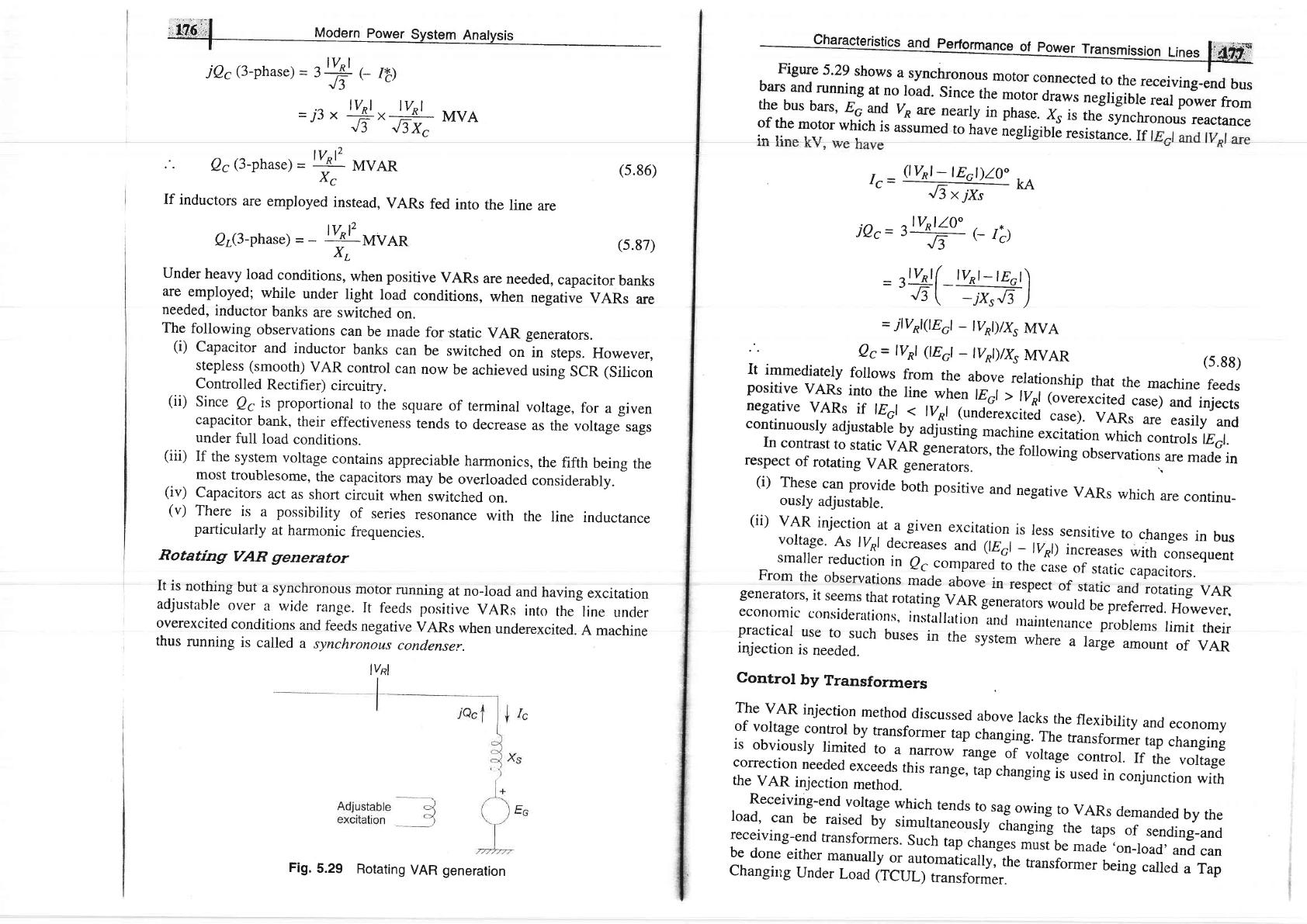
Rotating
VAR grenerator
It is
nothing
but
a
synchronous
motor
running
at
no-load
and
having
excitation
adjustable
over
a
wide
range.
It
feeds
positive
VARs
into
the
line
uncler
overexcited
conditions
and
f'eeds
negative
VARs
when
underexcited.
A
machine
thus
running
is
called
a
synchronous
condenser.
lvnl
for
a
given
voltage
sags
Fig.
5.29
Rotating
VAR generation
z=R+jx
,tig;'J
Modern
Power
System
Analysis
I
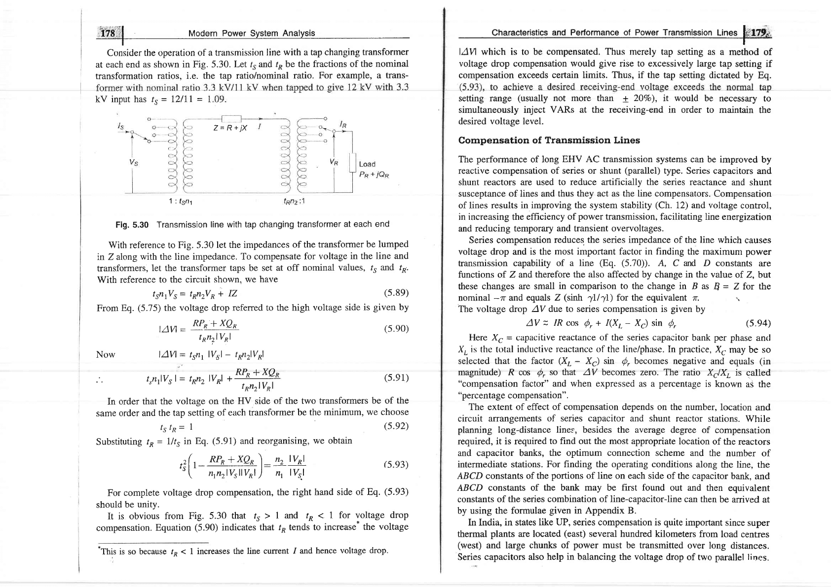
Consider
the
operation
of
a transmission line
with
a
tap changing transformer
at
each end as shown
in Fig. 5.30.
Let
/5
and
r^
be
the fractions of
the nominal
transformation
ratios, i.e. the tap
ratio/nominal
ratio.
For example, a
trans-
kV
input has rr
-
I2lll
=
1 : fsnl
Fig. 5.30
Transmission
line with tap changing
transformer
at
each
end
With reference to
Fig.
5.30
let the impedances
of the transformer
be lumped
tn Z along
with the line impedance.
To compepsate
for
voltage
in
the line
and
transformers,
let the transformer
taps be set
at off nominal
values,
rr and
ro.
With reference
to the circuit
shown. we
have
trnrVs= t^nrVo+
IZ
(s.8e)
From
Eq.
(5.75)
the
voltage drop
ref'erred to the high voltage
side is
given
by
tAvl
=
!I,!jIQs-
t
on,rlVol
lAVl
-
tsn,
lTsl
-
ton2lVol
Characteristics
and
Performance of Power Transmission
Lines
fi.l7!J,
I
l.{Vl
which is to be compensated.
Thus merely
tap setting as a
method
of
voltage drop compensation
rvould
give
rise to excessively
large tap
setting if
compensation exceeds
certain limits. Thus, if the
tap setting dictated
by Eq.
setting range
(usually
not more than + 20Vo),
it
would
be necessary
to
simultaneously inject
VARs at the receiving-end in
order to maintain
the
desired
voltage
level.
Compensation
of Transmission Lines
The
perfonnance
of
long
EHV AC transmission
systems can be improved
by
reactive compensation
of series or shunt
(parallel)
type.
Series capacitors
and
shunt reactors are used to
reduce artificially the
series reactance
and shunt
susceptance
of lines and thus
they act as the line compensators.
Compensation
of lines
results in improving the system stability
(Ch.
12) and voltage
conffol,
in
increasing
the
efficiency of
power
transmission, facilitating
line energization
and reducing
temporary
and
transient overvoltages.
Series compensation
reduces. the series impedance
of the
line
which
causes
voltage
drop
and
is the
most
important factor
in finding
the maximum power
transmission capability
of a
line
(Eq. (5.70)).
A, C and D constants
are
functions of Z and
therefore the also affected by change in the value
of. Z, but
these
changes are small
in comparison to the change
in B as
B
=
Z for the
nominal
-rr
and
equals Z
(sinh
4ll)
for the equivalent
zr.
.,
The
voltage
drop
AV due to series compensation is
given
by
AV
=
1R cos
S,
+ I(X,.
-
X.) sin ,!,
(s.e4)
Here
X,
=
capacitive reactance of the series capacitor
bank
per
phase
ancl
X,
is thc
total
incluctive rcactance of
the
line/phasc. In
practice,
X.
may be so
selected that the
factor
(XL
-
X.) sin
Q,
becomes
negative
and
equals
(in
magnitude) R cos
/,
so that AV
becomes zero. The
ratio X=IXL
is
called
"compensation
factor"
and when expressed
as a
percentage
is
known
as the
"percentage
compensation".
The extent of
effect of compensation depends
on the number,
location
and
circuit
arrangements
of series capacitor and
shunt reactor
stations. While
planning
long-distance
lines, besides the average
degree
of compensation
required,
it is required
to find out the most appropriate
location
of the
reactors
and capacitor banks,
the optimum connection scheme
and the
number
of
intermediate stations.
For finding the operating conditions
along
the
line, the
ABCD constants of the
portions
of line
on
each
side of the capacitor
bank,
and
ABCD
constants of the
bank may
be
first found
out and
then
equivalent
constants
of the series
combination of line-capacitor-line
can then
be
arrived
at
by
using the formulae
given
in Appendix B.
In India, in states
like UP, series compensation is
quite
important
since
super
thermal
plants
are located
(east)
several hundred kilometers
from
load
centres
(west)
and large
chunks of
power
must be
transmitted
over long
distances.
Series
capacitors also help
in
balancing the voltage
drop of two parallel
lines.
Now
(s.e0)
(s.e1)
In
order that
the voltage
on the
HV side
of
the
two transformers
be of
the
same
order and
the tap setting
of each
transformer
be the
minimum,
we choose
tstn=
1
(5.92)
SubstitutinE
tn=
llttin
Eq.
(5.91)
and
reorganising,
we obtain
trnrlvrl-
tonrlvol
+
RPR+xQR
t
*nrlVol
.r( ,
RPR
+xgo
) _
n2 lvRl
"['
"r"rWW
)-
",
W
(s.93)
For
complete
voltage drop
compensation,
the
right hand side
of Eq.
(5.93)
should
be unity.
It
is obvious
from
Fig. 5.30
that rr
> 1 and
tn 1 I
for voltage
drop
compensation.
Equation
(5.90)
indicates
that
/^
tends
to increase*
the
voltage
-This
is so
because fn
< 1 increases
the line
current / and
hence
voltage
drop.
r-hOt"
l uodern
Power
Svstem
Analysis
When
series
compensation
is
used,
there
are
chances
of sustained
overvoltage
to
the
ground at
the
series
capacitor
terminals.
This
overvoltage
can
be the
power
limiting
criterion
at
high
degree
of compensation.
A
spark
gap with a
high
speed
contactor
is
used
to
protect
the capacitors
under
overvoltage
trons.
Under
light
load
or
no-load
conditions,
charging
current
should
be kept
less
than
the
rated
full-load
current
of
the
line.
The
charging
current
is
approxi-
mately
given by
BrltA
where
B.
is the
total
capacitive
susceptance
of the
line
and
lVl
is the
rated
voltage
to
neutral.
If
the total
inductive
susceptance
is
Br due
to
several
inductors
connected
(shunt
compensation)
from
line
to
neutral
at
appropriate
places along
the
line,
then
the
charging
current
would
be
Characteristics and
Performance
of Power Transmission
Lines
kW
at a
leading
power
factor. At what value
of
P
is the
voltage
regulatior
zero
when the
power
factor
of the load
is
(a)
0.707,
(b)
0.85?
5.2
AlonglinewithA
=D=0.9
l1.5"andB=
150 165" CIhasatthe
loar
end a transformer having a series impedance Zr
=
100
167" Q. The
loar
form of
and evaluate
these constants.
5.3 A three-phase overhead line 200 km long has resistance
=
0.16 Qlkrn
an
conductor diameter
of 2 cm with spacing 4 m,
5 m and
6 m transpose(
Find:
(a)
the ABCD constants
using Eq.
(5.28b), (b)
the V,,
1,,
pf,,'I
when the line
is
delivering
full load of 50 MW at 132
kV and
0.8 laggin
pf,
(c)
efficiency
of
transmission,
and
(d)
the
receiving-end
voltag
regulation.
5.4 A short
230
kV transmission line with a reactance
of 18
O/phase
supplir
a load at
0.85 lagging
power
factor. For a line
current
of
1,000
A
tt
receiving- and
sending-end voltages are to be
maintained
at 230
k\
Calculate
(a)
rating of synchronous capacitor required,
(b)
the loa
current,
(c)
the
load
MVA.
Power drawn by the
synchronous
capacitt
may be neglected.
.\
5.5 A
40
MVA
generating
station is connected
to a
'three-phase
line
havin
Z
=
300
175"
Q
Y
=
0.0025 19tr
U.
The
power
at
the
generating
station is 40
MVA at unity power
factor
a
a voltage of L20 kV. There is
a load of 10 MW
at unity
power
factor
a
the mid
point
of
the
line.
Calculate the voltage
and
load at the
distant
enc
of
the
line.
Use
nominal-T
circuit for the line.
5.6
The
generalized
circuit constants of a transmission
line
are
A-0.93+70.016
B=20+
jI40
The load at the receiving-end is
60 MVA, 50 H4
0.8
power
factor
lagging. The voltage at the supply end is 22O
kV.
Calculate the
load
voltage.
Find the incident
and
reflected currents
for the line of Problem
5.3 at
the
receiving-end and 200 km from the receiving-end.
If
the line of Problem 5.6
is 200 km long
and delivers
50 MW at22OkY
and 0.8
power
tactor lagging, determine
the sending-end voltage,
current,
power
factor and
power.
Compute the efficiency
of transmission,
characteristic
impedance, wavelength,
and
velocity
of
propagation.
For Example
5.7
find the
parameters
of the
equivalent-n
circuit for
the
line.
r81
ff]
=
[1
",]l';l
(s.es)
Reduction
of the
charging
current
is by
the
factor
of
(1
-
Br lBc)
and
81lBg
is
the
shunt
compensation
factor.
Shunt compensation
at
no-load
also
keeps
the
receiving
end
voltage
within
limits
which
would
otherwise
be
quite
high
because
of
the
Ferranti
Effect.
Thus
reactors
should
be
introduced
as load
is
removed,f<lr
proper
voltage
control'
As
mentioned
earlier,
the
shunt
capacitors
are
used
across
an
inductive
load
so
as
to
provide
part'of the
reactive
VARs
required
by
the
load
to
keep
the
voltage
within
desirable
limits.
Similarly,
the
shunt
reactors
are
kept
across
capacitive
loads
or in
light
load
conditions,
as
discussed
above,
to absorb
some
of
the
leading
VARs
for
achieving
voltage
control.
Capacitors
are
connected
eithcr
clirectly
to a
bus
or
through
tcrtiary
wincling
of
the main
transformer
and
are
placed
along
the
line
to minimise
losses
and
the
voltage
drop.
Ii
may
be
noted
that
for
the same
voltage
boost,
the
reactive
power
capacity
of
a shunt
capacitrtr
is
greater
than
that of
a series
capacitor.
The
shunt
capacitor
improves
the
pf of the
load
while
the series
capacitor
has
hardly
any
impact
on
the
pf.
Series
capacitors
are
more
effective
for
long
lines
for
irnprovement
of
system
stability.
Thus,
we
see
that
in both
series
and
shunt
compensation
of
long
transmission
lines
it
is
possible
to
transmit
large
amounts
of
power efficiently
with
a flat
voltage
profile.
Proper
type
of
compensation
should
be
provided
in
proper
quantity
at appropriate
places to
achieve
the
desired
voltage
control.
The
reader
is
enceuraged
to
read
the
details
about
the Static
Var Systems
(SVS)
in
References
7, 8
and
16.
For
complete
treatment
on
'compensation',
the
reader
may
refer
to ChaPter
15.
PROB
!.EMS
A
three-phase
voltage
of
11
kV
is
applied
to a
line having
R
=
10
f) and
X
=
12
ft
p"t conductor.
At
the end
of the
line
is a
balanced
load
of
P
I,he,=
(Bc-
Br)
lvl
=
BclV
f[r
+)
5.7
5.8
5.9
5.1
,,1€?
il
uooern
power
system
hnalysis
-T-
5.10
An
interconnector
cable
having a reactance of
6
O links
generating
stations
1 and
2 as shown
in Fig.
5.18a.
The desired
voltage
profile is
lVtl
=
lVzl
=
22
kY. The
loads at the two-bus
bars are
40 MW at 0.8
lagging
power factor
and 20 MW
at
0.6
lagging
power
factor,
respectively. The
torque
angle and
the station
power
factors.
5.11
A 50
Hz,
three-phase,275
kV,
400 km transmission
line
has following
parameters
(per
phase).
Resistance
=
0.035 Qlkm
,
Inductance=1mFl/km
Capacitance
=
0.01
p,Flkm
If
the line
is supplied
at 275 kV,
determine
the MVA
rating of a shunt
reactor
having
negligible
losses that
would
be required
to maintain
275
kV
at the
receiving-end,
when the line is
delivering no-load.
Use nominal-
zr method.
5.12
A,three-phase
feederhaving
a resistance
of
3
Q
and areactance
of 10 f)
supplies
a load of
2.0 MW
at 0.85 lagging
power
factor. The
receiving-
end
voltage
is maintained
at
11
kV
by means of
a static condenser
drawing
2.1 MVAR
from
the line. Calculate
the sending-end
voltage and
power
factor.
What is the
voltage regulation
and efficiency
of the
feeder?
5.13
A three-phase
overhead
line
has resistance
and reactance
of 5
and 20 Q,
respectively.
The load at
the receiving-end
is 30 MW, 0.85
power
factor
lagging
at 33 kV.
Find the
voltage at the sending-end.
What will be the
kVAR
rating of the
compensating
equipment
inserted at the
receiving-end
so as
to maintain
a
voltage
of 33
kV at each
end? Find also
the maximum
load that
can be
transmitted.
5.I4
Construct
a receiving-end
power
circle diagram
for
the line of Example
5.7.
Locate
the
point
coresponding
to the load
of 50 MW
at 220 kV with
0.8
lagging
power
factor.
Draw the
circle
passing
through the
load
point.
Measure
the radius and
determine
therefrom lVrl.
Also draw
the sending-
end
circle
and determine
therefrorn
the sending-end
power
and
power
factor.
5.15
A
three-phase
overhead
line
has resistance
and reactance
per phase
of 5
and
25
f), respectively.
The load
at the receiving-end
is 15 MW, 33
kV,
0.8
power factor lagging.
Find the capacity
of
the compensation
equipment
needed
to deliver
this load
with a sending-end
voltage of 33
kv.
Calculate
the
extra
load
of
0.8
lagging
power
factor
which can be
delivered
with the
compensating
equipment
(of
capacity as calculated
above)
installed,
if the
receiving-end
voltage
is
permitted to drop to
28
kV.
characteristics
and
Performance
of
power
Transmission
Lines
183
REFERE
N
CES
Books
l. Tron'smission
Line Reference
Book-345
kV
and
Above,
Electric
Power
Research
Institute,
Palo Alto
calif,
1975.
2.
Mccombe,
J. and F.J.
Haigh,
overhead-Iine
practice,
Macdonalel,
London,
1966.
3.
Stevenson,
w.D.,
Elements
of Power
Sy.stem Analysis,4th
edn,
McGraw-Hill.
New
York,
1982.
4. Arrillaga,
J., High
Vohage
Direct
Curuent
Transmission,
IF,E Power
Engineering
Series
6, Peter
Peregrinus
Ltd.,
London,
1983.
5. Kirnbark,
E.w.,
Direct
current Transmission,
vol.
1, wiley,
New
york,
1971.
6. IJhlmann,
E., Power
Transmission
by
Direct
current,
Springer-verlag,
Berlin-
Heidelberg,
1975.
7.
Miller,
T.J.E.,
Reactive
Power
control
in Electric
systems,
wiley,
New
york
t982.
8. Mathur,
R.M.
(Ed.),
Static
Compensators
for
Reactive
Pub.,
Winnipeg,
1984.
9.
Desphande,
M.V.,
Electrical
Power
System Design,
Delhi,
1984.
Power
Control,
Context
Tata
McGraw-Hill.
New
Papers
10.
Dunlop,
R.D.,
R.
Gutman
and
D.p.
Marchenko,
"Analytical
Development
of
Loadability
Characteristics
for
EHV
and
UHV
Transmission
Lines",
IEEE
Trans.
PAS, 1979,98:
606.
11.
"EHV
Transmission", (special
Issue),
IEEE
Trans,
June
1966,
No.6,
pAS-g5.
12.
Goodrich,
R.D.,
"A
Universal
Power
circle Diagram",
AIEE
Trans.,
1951, 7o:
2042.
Indulkar,
c.s. Parmod
Kumar
and
D.p.
Kothari, "sensitivity
Analysis
of
a
Multiconductor
Transmission
Line",
Proc.
IEEE,
March
19g2,
70:
299.
Indulkar,
c.s.,
Parmod
Kumar
and
D.P.Kothari,
"some
studies
on
carrier
Propagation
in
overhead
rransmission
Lines",
IEEE
Trans.
on
pAS,
No. 4,
19g3,
102:
942.
Bijwe,
P.R.,
D.P.
Kothari,
J.
Nanda
and
K.s.
Lingamurthy, "optimal
voltage
Control
Using
Constant
Sensitivity
Matrix",
Electric
Power
System
Research,
Oct.
1986,
3: 195.
Kothari,
D.P., et al.
"Microprocessors
controlled
static
var
s5istems",
proc.
Int.
conf.
Modelling
&
Simulation,
Gorakhpur,
Dec.
1985,
2: 139.
13.
14.
15.
16.