Kothari D.P., Nagrath I.J. Modern Power Systems Analysis
Подождите немного. Документ загружается.

ffil
Modern
Power system
Analys
I
vaiue by
adjus'ring
speed
changer
setting,
the
system
could
under
go
intolerable
dynamic
frequency
changes
with changes
in load.
It leads
to
the
natural
suggestion
that
the
speed
changer
setting
be
adjusted
automatically
by
monitoring
the
frequency
changes.
For
this
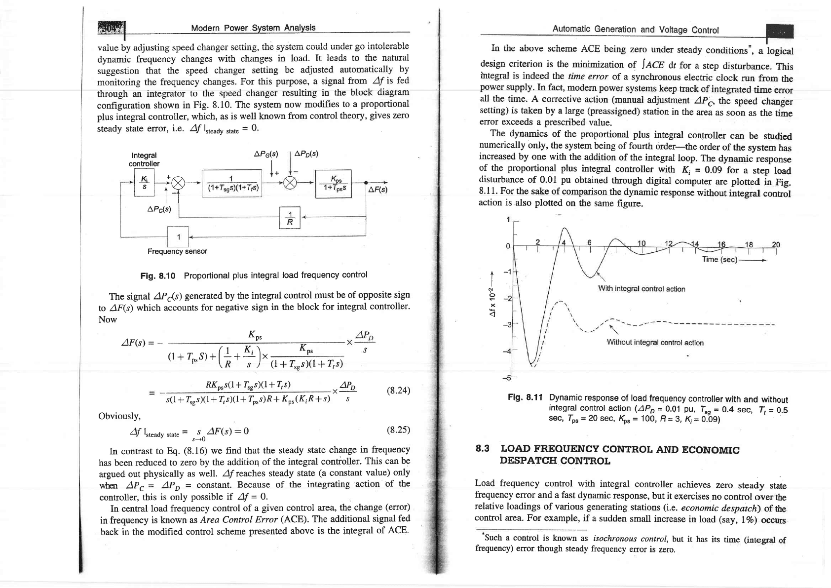
purpose, a signal
from
Af
is fed
througfan
integrator
to the
s
diagram
configuration
shown
in Fig.
8.10.
The system
now modifies
to a
proportional
plus integral controller,
which,
as is
well known
from
control
theory,
gives
zero
steady
state
error,
i.e. Af
lrt""d"
,,ut,
=
0.
Integral
controller
APp(s)
AP6(s)
Frequency
sensor
Fig.
8.10
Proportional
plus
integral
load
frequency
control
The signal
APr(s)
generated
by the
integral
control
must
be
of opposite
sign
to /F(s)
which
accounts
for negative
sign in
the block
for
integral
controller.
Now
(l*f,rs)(l+4s)
RKo,s(l+
{rs)(l+
4s)
obviousry
+
{'s)(1
+
4sXl
f
zo's)R
*
Ko'
(KiR
f
s)
Af
l"t"^dy
state
=
,
so/F(s)
:
o
In contrast
to
Eq.
(8.16)
we
find
that the
steady
state
change
in
frequency
has been
reduced
to
zero by
the additio4
of
the integral
controller.
This can
be
argued
out
physically as
well. Af
reaches
steady
state
(a
constant
value)
only
rr.,lrsrr Ap^
-
Ap- = .ons-fant Becarrs-e of fhe intes!'atins actiOn Of
the
wlMl
urc-
HrD
-
vvuulqr!.
controller,
this
is only
possible if Af
=
0.
In central
load
frequency
control
of a
given control area,
the change
(error)
in frequency
is known
as
Area Contol
Error
(ACE).
The
additional
signal
fed
back in
the modified
control
scheme
presented above
is the
integral
of ACE.
l+t-r8-
I I t-+
tl
Kn,
AF(s1
=
(r
+
%"s).
(*
*
+).
Ko,
"+
APe(s)
-1
+
I
I
t
o
r
x
AF(s)
Automatic
Generation
and
Voltage
Control
t-
in ihe
above scheme
ACE
being
zero uncier
steaciy
conditions*,
4 logical
design
criterion
is
the minimization
of
II,CZ
dr for
a
step
disturbance.
This
integral
is
indeed
the
time
error
of a synchronous
electric
clock
run
from
the
power
supply.
Infact,
modern powersystems
keep
Eaekofintegra+e4tinae
errsr
all
the
time.
A corrective
action
(manual
adjustment
apc,
the
speed
changer
setting)
is
taken
by a large
(preassigned)
station
in
the
area
as
soon
as
the
time
error
exceeds
a
prescribed
value.
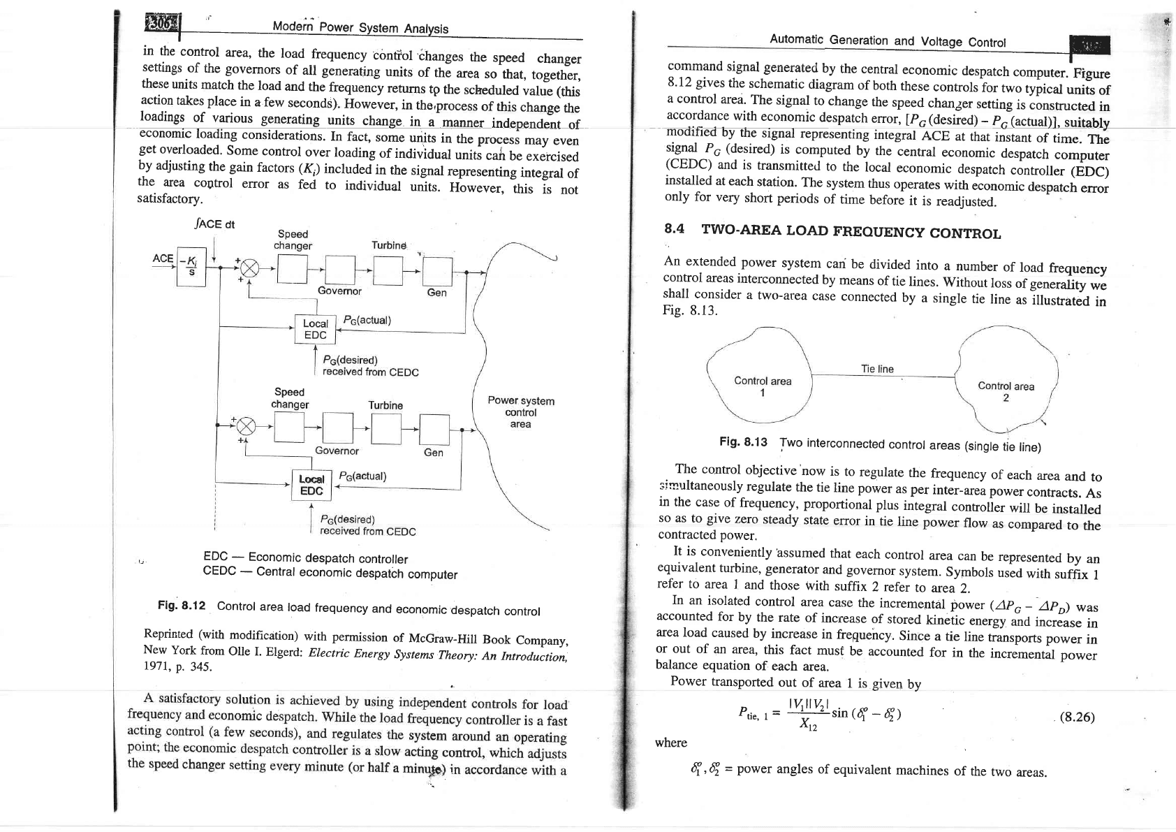
The
dynamics
of the
proportional
plus
integral
controller
can
be studied
numerically
only,
the
system
being
of fourth
order-the
order
of the
system
has
increased
by
one with
the addition
of the
integral
loop.
The
dynamic
response
of the
proportional
plus
integral
controller
with
Ki
=
0.09
for
a
step
load
disturbance
of 0.01
pu
obtained
through
digital
computer
are
plotted
in
Fig.
8.11. For
the sake
of comparison
the dynamic
response
without
integral
control
action
is
also
plotted
on
the same
figure.
Flg.
8.11
Dynamic
response
of load
frequency
controller
with
and without
integral
control
action
(APo
=
0.01
pu,
4s
=
0.4
sec,
Ir
=
0.5
sec,
Ips
=
20 sec,
Kp.
=
100,
B
-
B, Ki=
0.-09)
8.3 IOAD
FREOUENCY
CONTROL
AND
ECONOMIC
DESPATCH
CONTROL
Load freouencv control with inteorel eonfrnller
qnhierrAe
?a?^ craolrr ora+o
I
__J ________
,.___
_---_O
'vu
lvrv
otvsuJ
Dl4lg
frequency
elTor and
a fast
dynamic
response,
but
it
exercises
no
control
over
the
relative
loadings
of
various
generating
stations
(i.e.
economic
despatch)
of
the
control area.
For
example,
if a
sudden
small
increase
in load
(say,
17o)
occurs
'Such
a control is
known
as isochronous
control,
but
it
has
its time
(integral
of
frequency)
error
though steady
frequency
error
is
zero.
(8.24)
(8.25)
1i..l1r_::ltrol
area,
the
road
-frequency
conrior
,changes
the
speed
changer
Dcrurgs
or
tne governors
of
all generating
units
of
the
area
so
that,
together,
these
units
match
the
load
and
the
frequenry
returns
tp
the
scheduled
value
(this
action
takes
place
in
a few
seconds).
However,
in
the,process
of this
change
the
Ioadings
of u@units
change
in
a
manner
independent
of
economi@
In
fact,
some
units
in
the pro""r,
may
even
get
overloaded.
Some
control
over
loading
of
individual
units
cafi
be
Lxercised
by
adjusting
the gain
factors (K,)
includeJin
the
signal
representing
integral
of
the
area
cogtrol
error
as
fed
to
individual
unitr.
However,
this
is
not
satisfactory.
lr.
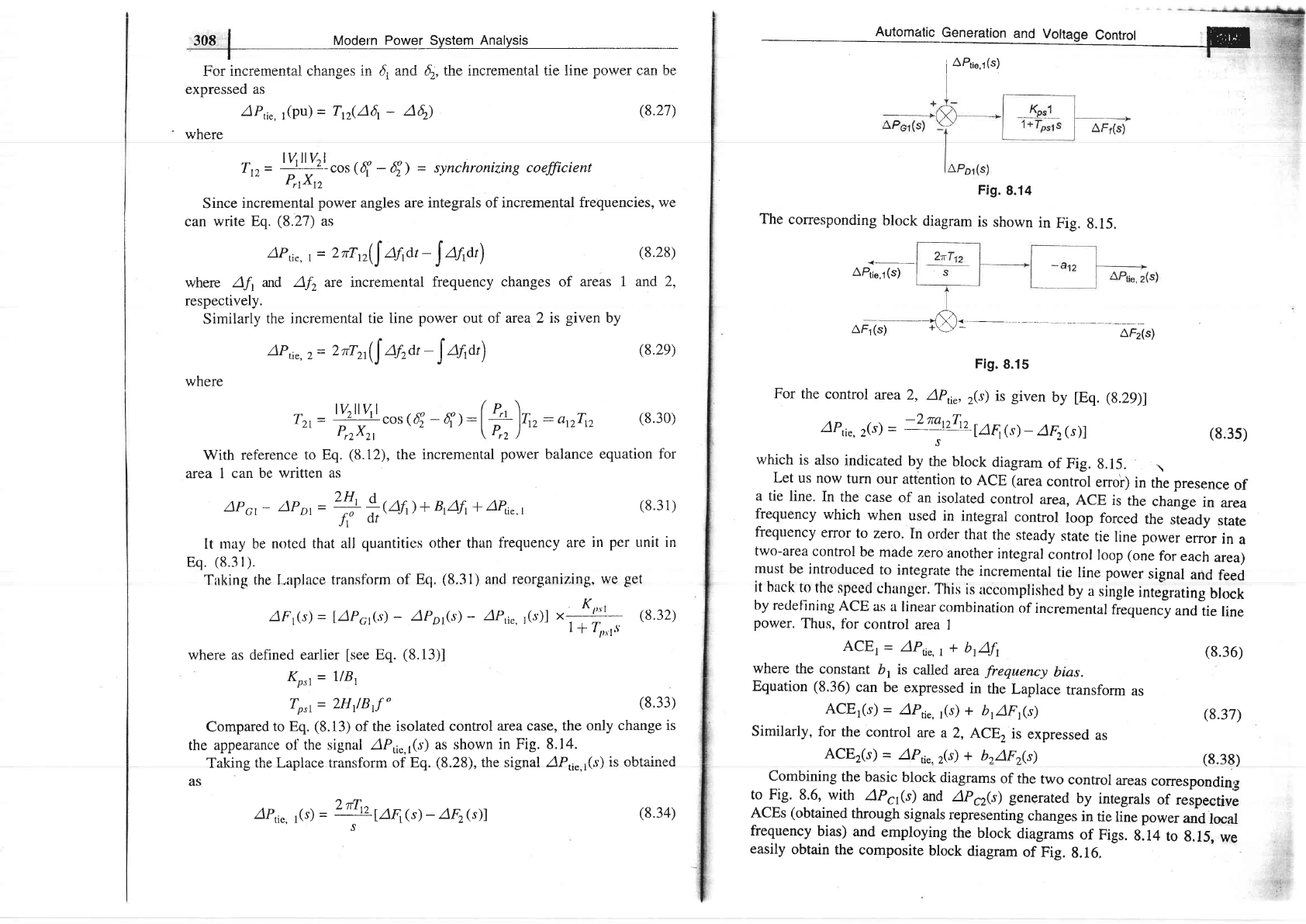
EDC
-
Economic
despatch
controller
CEDC
-
Central
economic
despatch
computer
Flg.
8-12
Control
area
load
frequency
and
economic
despatch
control
Reprinted
(with
modification)
with permission
of
McGraw-Hill
Book
Company,
New
York
from
Olle I.
Elgerd:
Electric
Energy
Systems
Theory:
An Introd.uction,
I971,
p.
345.
"fnce
ot
Speed
Automatic
f
_T---
command
signai generated'oy
the
centrai
economic
despatch
computer.
Figure
8'12
gives
the
schematic
diagram
of
both
these
controlsior
two
typi.ut
units
of
a
control
area.
The
signal
to
change
the
speed
chan3er
setting
is
lonstructed
in
accordance
with
economic
despatch
error,
[po
(desired)
-
pJactual)].
suitabry
modified
by
the
signal
representing
integral
ncg
at
that
instant
of
time.
The
signal
P6
(desired)
is
computed
by
the
central
economic
despatch
computer
(CEDC)
and
is
transmitted
to
the
local
econornic
despatch
controller
(EDC)
installed
at
each
station.
The
system
thus
operates
with
economic
desfatch
error
only
for
very
short
periods
of
time
beforJ
it
is
readjusted.
8.4
TWO-AREA
LOAD
FREOUENCY
CONTROL
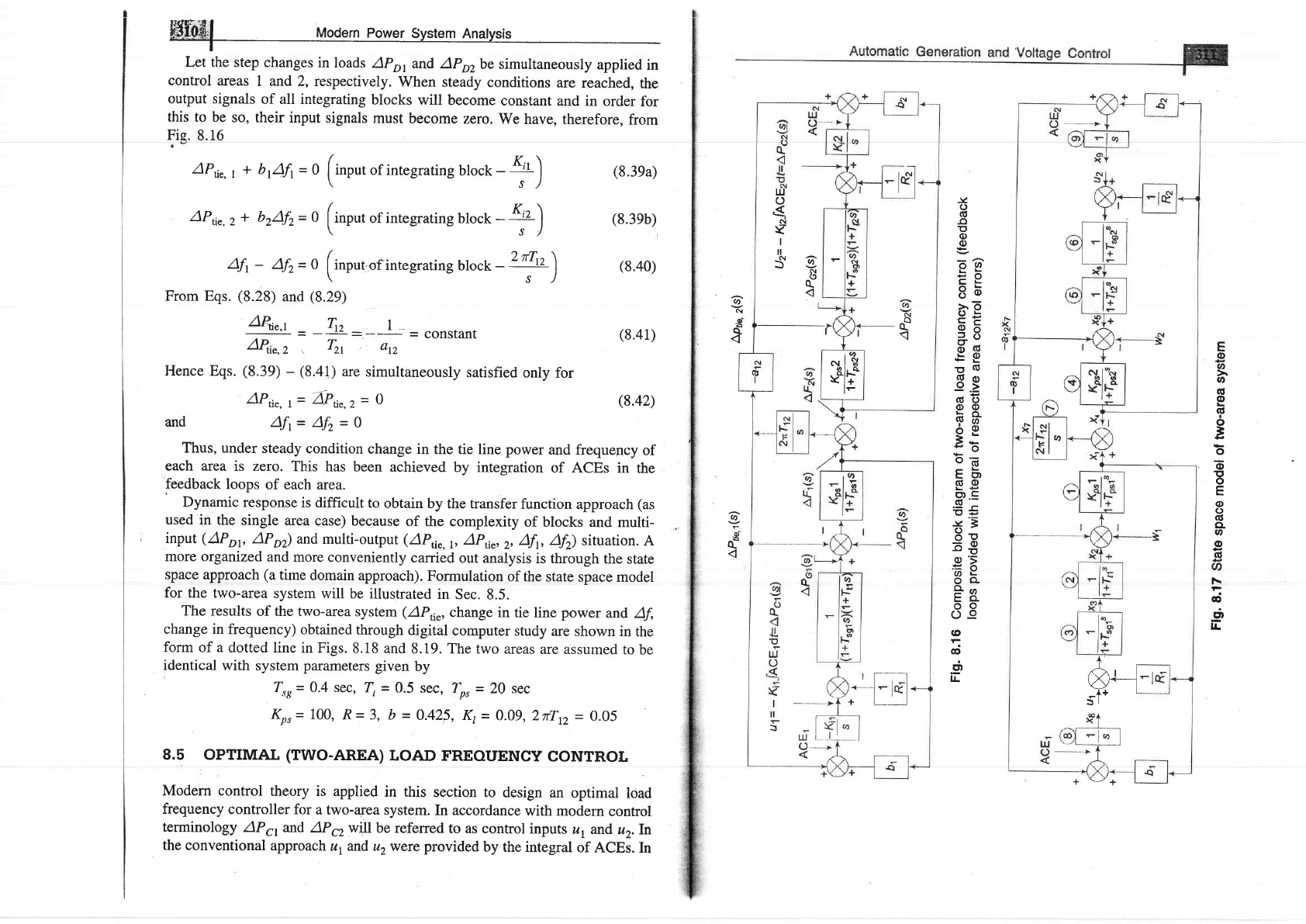
An
extended
power
system
can
be
divided
into
a
number
of
load
frequency
control
areas
interconnected
by
means
of
tie
lines.
Without
loss
of generality
we
shall
consider
a
two-area
case
connected
by
a
single
tie
line
as
lilusnated
in
Fig.
8.13.
Fig.
B.i3
Two
interconnected
contror
areas
(singre
tie
rine)
The
control
objective
now
is
to
regulate
the
frequency
of
each
area
and
to
srnnultaneously
regulate
the
tie
line power
as per
inter-area
power
contracts.
As
in
the
case
of frequency,
proportional
plus
integral
controller
will
be
installed
so
as
to
give
zero
steady
state
error
in
tie
line power
flow
as
compared
to
the
contracted
power,
It
is
conveniently
hssumed
that
each
control
area
canbe
represented
by
an
equivalent
turbine,
generator
and governor
system.
Symbols
used
with
suffix
I
refer
to
area
7 and
those
with
suffi
x
2 refer
to
area
2.
In
an
isolated
control
area
case
the
incremental
power
(apc
_
apo)
was
accounted
for
by
the rate
of
increase
of
stored
kinetic
energy
and increase
in
area
load
caused
by
increase
in
fregueircy.
since
a
tie
line
t
*rport,
power
in
or
out
of
an
area,
this
fact
must
be
accounted
for
in
the
incremental
power
balance
equation
of
each
area.
Power
transported
out
of
area
1 is
.eiven
bv
Ptie,
r
=
''rrl''l
sin
({
-
q
X,,
where
q'q
-
power
angles
of
equivalent
machines
of
the
two
areas.
(8.26)
I
308
|
Modefn Power System
Analysis
I
For
incremental changes
in
{
and 6r, the incre.mental tie line
power
can be
expressed as
AP,i,,
r(pu)
=
Tp(Afi
-
462)
where
T,
=
'Y:t'-Yf
cos
(f
-
E)
-
synchronizing
coefficient
PrrXrz
Since
incremental
power
angles
are integrals of incremental frequencies,
we
can
write Eq.
(8.27)
as
AP,i,,
r
=
2*.(l Afrdt
-
I
Urat)
where
Afi
nd Af,, arc incremental
frequency changes of
areas 1
respectively.
Similarly
the incremental
tie line
power
out of
area 2 is
given
by
aPt;",
z
=
2ilzr([
yrat
-
[
ayrat)
where
rzr
=
tYr:J
cos
({
-
E): [S]ti z:
ar2rrz
(s.30)
LL
Przxzr
L
"
\Prr)
With reference
to Eq.
(8.12),
the incremental
power
balance
equation
for
area 1 can
be written as
APo,
-
APor
=
+ *w)+
nrz|r* AP,,",t
Jr"
or
(8.27)
(8.28)
and 2,
(8.2e)
It
rnay be noted
that all
quantities
other
than fiequency
are
in
per
unit in
Eq.
(8.3l).
Taking
the l-aplace transf'orm
of Eq.
(8.31)
and
reorganizing,
we
get
AF(s)
=
IAP61G)
-
APr,(s)
-
APti",,1r;]
"t$-
$.32)
I
+
4,,t,!
where as defined earlier
[see
Eq.
(8.13)]
Kp31
=
I/81
Tpil
=
LHr/BJ"
Compared
to Eq.
(8.13)
of the isolated
control
area case, the
only change
is
the appearance
ol
the signal APri"J
(s)
as shown
in Fig. 8.14.
'-l'^Li--
fho T -^l-^a f*onofnrm ^f E^ /a ta\ tha cionol ,4P /"\ ic nlrfoinerl
I4ArrrS
rrrw lsl/l4vv
Ll4llDrurrrr ur
LY.
\v.L9),
llrv
or6rrs^
",
tie.I\.r/
AS
AP,i.,1(s)
=
ffroor(s)
-
/4
(s)l
(8.31)
(8.33)
(8.34)
Automatic
Generation
and
Vortage
contror
Fil
I
APti".r(s)
Fig.
8.14
The
corresponding
block
diagram
is
shown
in
Fig.
g.15.
+
APti",r(s)
AF1(s)
-iE=
--n7ri"l
Fig.
8.15
For
the
control
area
2, Ap6",
r(s)
is
given
by
tEq.
(g.Zg)l
apti",z(s)
=
-:grrr,
[AFr(s)
-
4F,
(s)]
(g:35)
which
is also
indicated
Uy ,i.
block
diagram
of
Fig.
8.15.
\
Let
us
now
turn
our attention
to
ACE
(area
control
error;
in
the
presence
of
a
tie line.
In the
case
of an
isolated
control
area,
ACE
is
the
change
in
area
frequency
which
when
used
in
integral
control
loop
forced
the
steady
state
frequency
elror
to
zero.
In
order
that
the
steady
state
tie
line
power
error
in
a
two-area
control
be
made
zero
another
integral
control
loop
(one
for
each
area)
must
be introduced
to integrate
the
incremental
tie
line
power
signal
and
feed
it
back
to
the
speed
changer.
This
is
aeeomplished
by a
single
integrating
bloek
by
redef
ining
ACE
as
a linear
combination
of
incremental
frequenry
and
tie
line
power.
Thus,
fbr
control
area
I
ACEI
=
APu".r+
brAf,
where
the
constant
b, is called
area
frequency
bias.
Equation
(8.36)
can
be
expressed
in
the
Laplace
transform
as
ACEl(s)
=
APo.,
r(s)
+
b1AF1g)
Similarly,
for
the
control
are
a
2,
ACE2
is
expressed
as
ACEr(s)
=
APti".z(s)
+
b2AF,(s)
Combining
the
basic
block
diagrams
of the
two
control
areas
corresponding
to
Fig.
8.6, with
AP5rg)
and
Apr2(s)
generated
by
integrals
of
respective
ACEs
(obtained
through
signals
representing
changes
in
tie
line power
and
local
frequency
bias)
and
employing
the
block
diagrams
of
Figs.
g.t+
to
g.15,
we
easily
obtain
the
composite
block
diagram
of
Fig.
g.16.
(8.36)
(8.37)
(8.38)
WIU&|
Modern
Power
svstem
Analvsis
Let
the step
changes
in loads
APo,
and
APrrbe
simultaneously
applied
in
control
areas
1 and
2, respectively.
When
steady
conditions
are
reached,
the
output signals
of all integrating
blocks
will
become
constant
and in
order
for
this to be
so, their input
signals
must
become
zero.
We have, therefore,
from
Fie.
8.16
APu",
,
+
b
rAfr=
O
finput
of integrating
block
-
KtL)
-
\
,r)
APti",
,
+
brAfr=
o
finpot
of integrating
block
-
K'z)
-
\
rl
Afr
-
Afz
=o
finpurot
integrating
block
-'4'\
-\s)
From Eqs.
(8.28)
and
(8.29)
APn",,
=-Tr,
-.
I.=constant
AP.i",z,
Tzt;
ar2
Hence Eqs.
(8.39)
-
(8.41)
are
simultaneously
satisfied
only
for
(8.39a)
(8.3eb)
(8.40)
(8.41)
(8.42)
and
Thus, under
steady
condition
change
in
the tie line
power
and frequency
of
each area
is zero.
This
has been
achieved
by integration
of
ACEs in
the
feedback
loops
of each
area.
Dynamic
response
is difficult
to
obtain by
the transfer
function
approach
(as
used
in the
single area
case)
because
of
the complexity
of blocks-and
multi-
input
(APop
APor)
and
multi-output
(APri",1,
Ap6",2,
Afr
Afr)
situation.
A
more
organized and
more
conveniently
carried
out analysis
is through
the
state
space
approach
(a
tirne
domain
approach).
Formulation
of the
state
space model
for the
two-area
system
will be
illustrated
in
Sec.
8.5.
The
results
of the two-area
system
(APri",
change
in tie line
power
and, Af,
change in
frequency)
obtained
through
digital
computer
study are
shown in
the
form
of
a
dotted line
in Figs.
8.18 and
8.19. The two
areas
are assumed
to
be
identical
with system
parameters
given
by
Trs= 0.4 sec,
7r
=
0.5
sec, ?r,
=
20 sec
Kor= 100,
R=3,
b=0.425,
&=0.09,2flr2=0.05
8.5 OPTTMAL
(TWO-AREA)
LOAD
FREOUENCY
CONTROL
Modern control
theory is applied
in this
section to
design
an
optimal
load
frequency
controller
for a
two-a3ea
system.
In accordance
with modern
control
terminology
APcr arrd
AP62
will be
referred
to as control
inputs
q and
u2.ln
the
conventional
approach
ul and uzwere provided
by the integral
of ACEs.
In
.Y
o
(U
-o
!t
o
g
oy,
EF
86
:pE
o6
=a
c)
-(d
E9
gtu
Qcl
e.>
(g()
oo
FA
OE
5*
*o
b6
tr(')
Eg
H'.s
*3
5u
=o
a'5
'89
oo.
*,n
EO-
oo
oo
@
d
<;
l!
E
o
o
o
o
o
G'
6
o
o
E
o
E
(D
()
(U
CL
.n
o
o
o
r\
ai
cit
lr
tt)
.9
d
APri",r=
AP,:",2=0
Afi=
Afz=0
a
(\
.g
q
<.1
t
l+
5l
-ld
trJ
o
oi
ra
I
il
SA
N
o
o-
u
I
f|:-
*li
ol.
a
v'it
lr
itZ
I
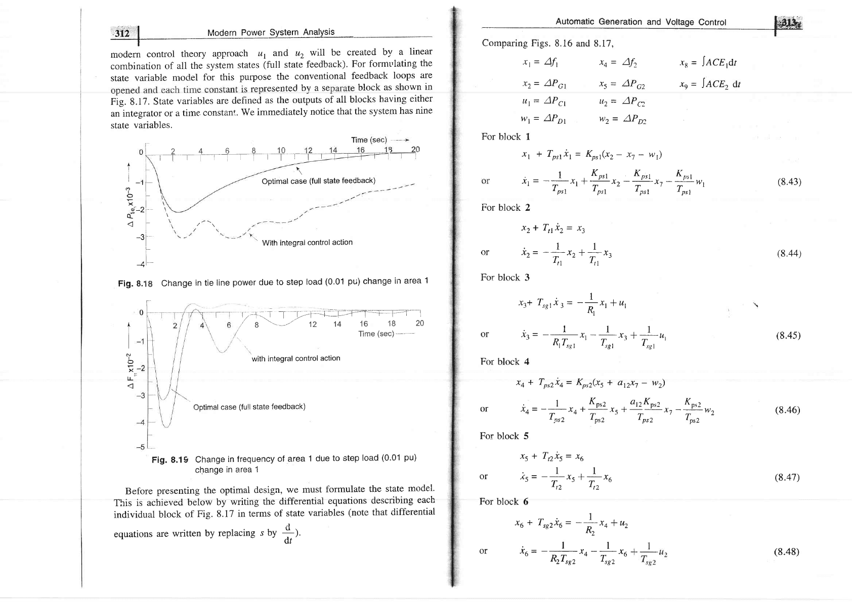
rrrrodern
Power
System
Analysis
-
modern
control
theory
approach
ur and
u2
wtll
be
created
by
a
linear
combination
of
all
the system
states
(full
state
feedback).
For
formt'lating
the
state
variable
rnodel
for
this
purpose the
conventional
feedback
loops
are
resented
bv a
se
block
as shown
in
Fig.
8.17.
State
variables
are
defined
as the
outputs
of all
blocks
baving
either
an integrator
or ar
tirne,
constanf..
We
immediately
notice
that
the
systern
has
nine
state
variables.
-1-+-r+--i,
-f-.'f--
\
Optimal
case
(full
state
feedback)
'
With
integralcontrol
action
change
in
tie
line
power
due
to step
load
(0.01
pu)
change
in
area
1
Automatic
Generation
and Voltage
controt
M&
f*
Comparing Figs.
8.16 and
8.17,
xt
=
Aft
.r2
-
AP,;1
xq
=
Af.
x5
=
AP52
XS
=
JACE
it
t,
=
JACE,
dt
I
t
t-
,I
18
-l
t'-2
-3
1
8.'
+
I
I
I
o
o
X
(
Fig.
A
L
I
N
I
o
x
IL
r;+-.1
I
-21.--+-_'--';-;;7-1=a.-1-1=--1
/'
8
'-
--'
12
14
16
18
20
/
Time
(sec)-----
tt1= APg,
w1=
AP"
For
block
1
x1
+
T.rri,
=
LP
.1
hl
-
4l
'psl
For
block 2
x.2+ Tiliz= xt
or *z=
-+-r**n
For
block 3
tr+
{,sri:
=
-Lrr+r,
'R,rr
or
*t=
-
^h
r,-
t*,**,,
For
block 4
Xn*
+
or iq=
For block
5
xst
or
is=
For block
6
xs*
u2
=
/)Pa
w2
=
APp,
K^t(xz-
h
-
w)
,
Kprt
,-
Kprt
-,
Kprt
*f
xz-;-xt
-;-wt
(8.43)
t
psl
t
ptl
t
ptl
(8.445
(8.45)
(8.46)
(8.47)
with
integral
control
action
Optimal
case
(full
state
feedback)
Fig. 8.19
Change
in frequency
of area
1 due
to step
load
(0.01
pu)
change
in a.rea
1
Before
presenting
the
optimal
design,
we must
formulate
the
state
model.
This
is
achieved
below
by
writing
the differential
equations
ciescribing
each
individual
block
of
Fig. 8.17
in terms
of state
variables
(note
that
differential
equations
are written
by
replacing
s UV
*1.
'
dt'
Torz*+=
Krrz(xs
+ ar2x7
-
wz)
I
Knrz
at?K
or2
Ko*2
'\A'1--.{<
-T-
--y'-a-_-W^
Tprz
-
Tps2
''
Tps2
'
Tpsz
z
7,2i5
-
x6
l1
Y I-V
4<t4l
Ttz
r
T,z
u
.l
I
,szx6
-
-;
x4
+
u2
I\2
or
io=
-#*o-**u
'2t
sg2
t
sg2
(8.48)
'3i4',"1
Modern Power System Anatysis
T
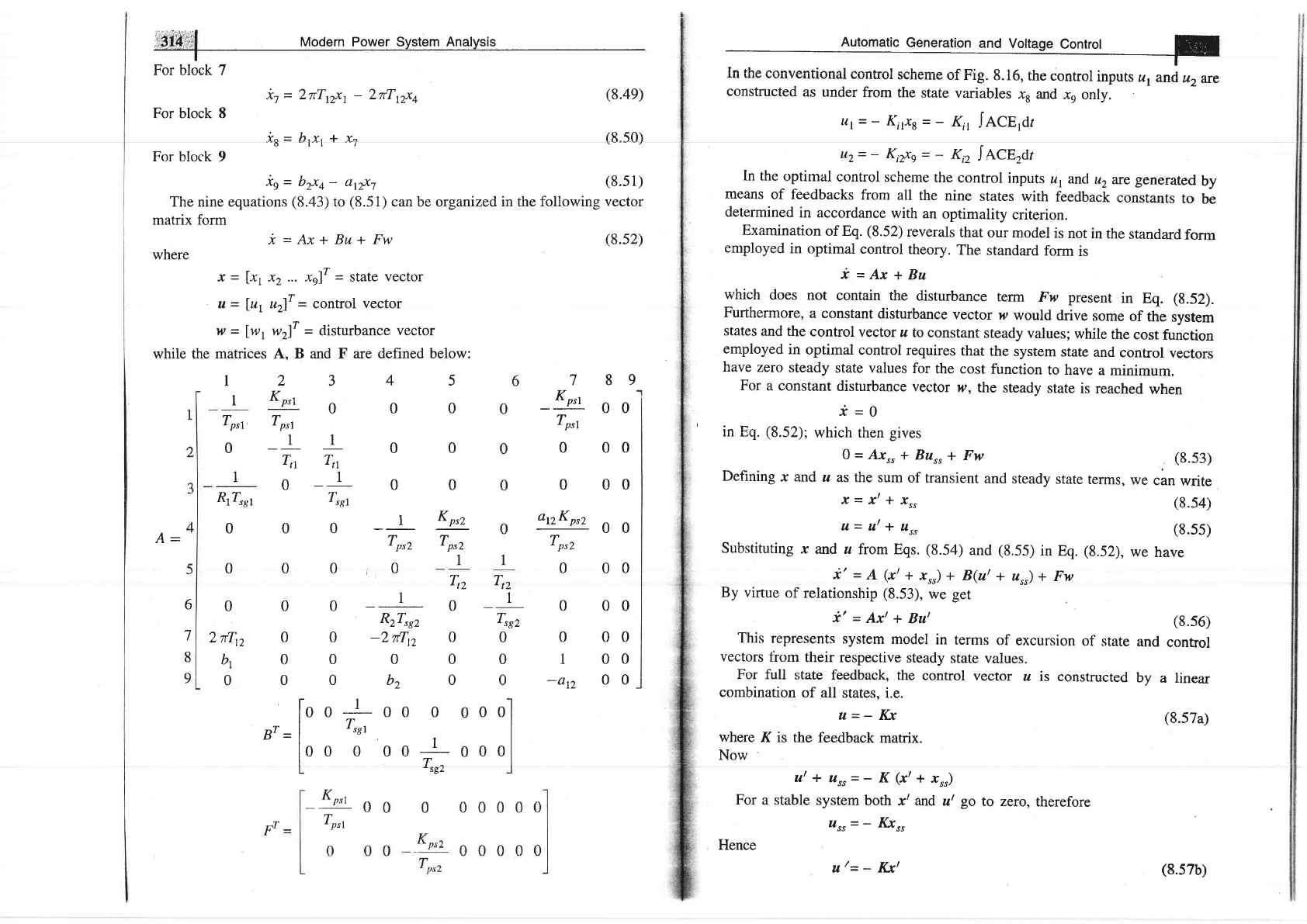
For block 7
it=2iTtzxt-2iTr2xa
For block 8
is=
brx,
+ x.i
For
block 9
(8.4e)
(8.5O-)
(8.s
1)
(8.s2)
i9=
b2xa- anxt
The nine equations
(8.43)
to
(8.51)
can be organized in
the following vector
matrix
form
A_
where
x_lxr
u=fut
w=lwt
while
the
matrices
*=Ax+Bu+Fw
x2 ... xg)r
=
state
vector
u2fT
=
control vector
w2fT
=
clisturbance
vector
A, B and F are defined below:
2345
Y
'tPsl
0 0
0
Tprt
-1
1
o
o
Tt Ttr
o
-1
o o
Trst
00-1Kp'z
Tprz Tprz
o
o
i
o
--1-
Ttz
I
I
Tpst,
0
1
Rr4er
0
0
0
2
irrz
bL
0
7 89
-bLoo
Tprt
0 00
0 00
atzKprz
0 0
Tprz
0 00
6
7
8
9
oo-10
RzTrsz
0
0
-2ilr2
0
0000
00b20
[oo
I
oo o
IT
Br
=
|
-ss1
loo
o oo+
I
aco)
L
'O-
1
7,,
I
TreZ
0
0
0
0
0
1
-atz
00
00
00
00
-
Kprt
0
Tprt
00.l
I
I
0 0l
I
J
,;T
(8.s7b)
"
'--
co","".t""
constructed
as under
from
the
state
variables
x, and
-rn
only.
ut=-
Kirxs=-
Kir
IeCn,Ar
uz=- Ki{s=-
Kiz
la.Cerar
ln the
optimal
control
scheme
the
control
inputs
u,
and
uz
are
generated
by
means
of feedbacks
from
all
the
nine
states
with
feedback
constants
to
be
determined
in accordance
with
an
optimality
criterion.
Examination
of Eq.
(8.52)
reverals
that
our
model
is
not in
the
standard
form
employed
in
optimal
control
theory.
The
standard
form
is
i=Ax+Bu
which
does not
contain the
disturbance
term
Fw present
in
Eq.
(g.52).
Furthermore,
a constant
disturbance
vector
p
would
drive
some
of
the
system
states
and the
control
vector
z
to constant
steady values;
while
the cost
function
employed
in
optimal
control
requires
that
the
system
state
and
control
vectors
have
zero
steady
state values
for
the cost
function
to have
a minimum.
For
a constant
disturbance
vector
w, the
steady
state
is reached
when
*=0
in
Eq.
(8.52);
which
then
gives
0=A.rr"
+
Burr+
Fw
(8.s3)
Defining
x
and z
as the
sum
of
transient
and
steady
state
terms,
we
can
write
,
x
=
x' *
Ir"
(8.54)
n
=
ut *
z',
(8.55)
Substituting
r
and z
from
Eqs.
(8.54)
and
(8.55)
in Eq.
(8.52),
we
have
i'
=
A
(r/
+
x"r) +
B(at
+
usr)
+ Fw
By
virtue
of relationship
(8.53),
we get
*'
=
Axt
+
But
(g.56)
This
represents
system
model
in
terms
of excursion
of
state
and
conhol
vectors
fiom
their
respective
steady
state
values.
For full
state
feedback,
the
control
vector
z is
constructed
by
a linear
combination
of all
states.
i.e.
u=- Kx
(8.57a)
where
K is
the feedback
matrix.
Now
ttt+
Itrr=-
l(
(r/+
rr")
For
a stable
system
both
r/
and
ut
go
to
zero,
therefore
ur,
=
_
Kx*
Hence
tt
/=
-
Ikl
Modern
Power
System
Analysis
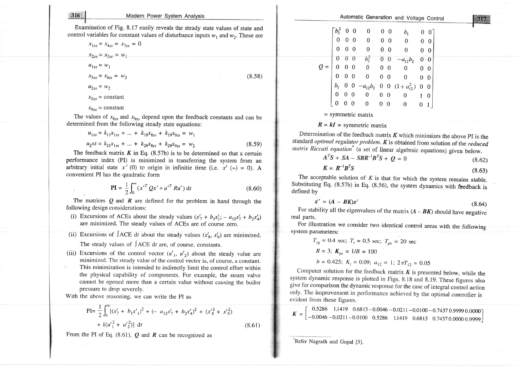
Examination
of Fig.
8.17 easily reveals
the steady
state
values of
state
and
control variables
for
constant values
of disturbance
inputs
w, andwr.
These are
Ilrr=X4"r=
/7r"
=
0
Automatic
Generation
b?o
00
00
00
00
00
0
00
0
00
0
00
0
00
400-anbz00
0
00
0
00
0
00
0
00
4
00
0
00
0
00
-arzbz
0
0
0
00
0
00
Q+a?)
o
o
0
10
0
01
(8.63)
for
which
the
system
remains
stable.
the
system
dynamics
with
foedback
is
0
0
0
0
0
0
ulr,
=
wl
r5rr= x6rr=
lv2
uzr,
=
wz
(8.s8)
Igr,
=
COnstant
I9r,
=
Constant
The
values
of
xr* and
xe* depend
upon
the feedback
constants
and
can
be
determined
from
the following
steady
state
equations:
utrr=
kttxtr, +
... +
ftt8r8", * kt*sr,
=
wl
r,t2ss
=
k2txlr,
+ ... +
kzgxgr., * kz*gr,
=
wz
(8.se)
The
feedback
rnatrix
K
in Eq.
(8.57b)
is
to be determined
so
that a certain
performance
index
(PI)
is
minimized
in transferring
the system
from
an
arbitrary
initial
state
x'
(0)
to origin
in
infinitie
tirne
(i.e.
x'
(-)
=
0).
A
convenient
PI
has the
quadratic
form
'
Pr
=
;ll
'.''
Qx'
+ u'r
Ru' dt
The
manices
Q
arrd
R are
defined
for
the
problem
in hand
through
the
followi
ng
design consiclerations:
(i)
Excursions
of ACEs
about the
steady
values
(r,t
+
brx\;
-
arrxt, +
bzx,q)
are minimized.
The steady
values
of ACEs
are
of course
zero.
(ii)
Excursions
of
JnCg
dr about
the
steady
values
(xts,
xte) are
nrinimized.
The steacly
values
of
JeCg
dt
are, of
course, constants.
(iii)
Excursions
o1'the
contt'ol
vector
(ut1,
ut2) about
the
steady
value
are
rninirnized.
The
steady value
of
the control
vector
is, of
course, a constant.
'
This
nrinimization
is intended
to
indirectly
limit
the control
effbrt
within
the
physical
capability
of components.
For
example,
the steam
valve
catmot
be opened
more than
a certain
value
without
causing the
boiler
presisure
to
drop severely.
With
the
above
reasoning,
we
can write
the
PI as
=
symmetric
matrix
R
-
kI
=
symmetric
matrix
K
=
R-rBrS
The
acceptable
solution
of
K
is
that
Substituting
Eq.
(8.57b)
in
Eq.
(8.56),
defined
bv
i'
=
(A
-
BIgx,
(g.64)
Fol
stability
all
thc
cigenvalues
of
the
matrix (A
-
Bn
should
have
negative
real
parts.
For
illustration
we
consider
two
identical
control
areas
with
the
following
syste|ll parameters:
4r*
=
0'4
scc;
T'r
=
0.5
sec;
7'r*
=
20
sec
/l
=
3:
(n*
=
l/lJ
=
100
b
=
O.425;
Ki
=
0.09;
up
=
I;
2iln
=
0.05
f, [
0.52tt6
l.l4l9
0.68
l3
-
0.0046
-0.021
|
-0.0100
-0.743
7
0.gggg0.00001
^
=
L-o.tl046-0.o2tl-0.0100
0.5286
t.t4rg
0.6813
0.74370.0000
0.gggsl
(8.60)
pr=
* fU-+
+
h,.r,,)2 +
(-
tt,2xt,
+
brxta)z +
(.r,?
+
,,])
2Jtt'
+
kfu'l +
u,|11
at
From
the
PI of
Eq.
(8.51),
Q
md R
can
be recognized
as
(8.61)
'*Refer
Nagrath
and
Gopal
[5].
iiii'f:l Modern
power
rystem
in4gs
As
the
control
areas
extend
over
vast geographical
regions,
there
are
two
ways
of
obtaining
full
state
information
in
each
area
for
control
purposes.
(i)
Transport
the
state
information
of
the
distant
area
over
communication
channels.
This
is,
of
course,
expensive.
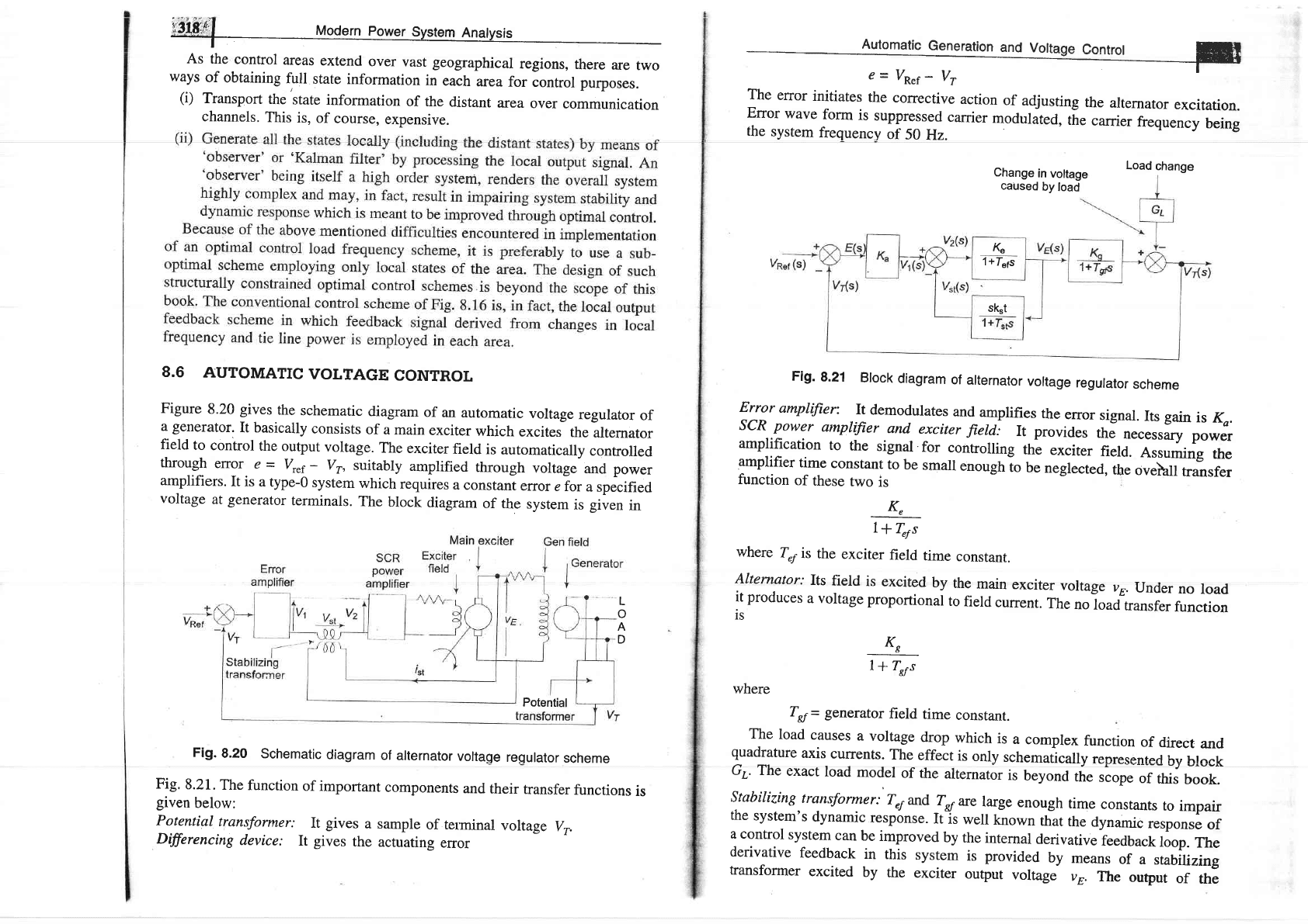
8.6
AUTOMATIC
VOLTAGE
CONTROL
Figure
8.20
gives
the
schematic
diagram
of
an
automatic
voltage
regulator
of
a generator.
It basically
consists
of
a
main
exciter
which
excites
the
alternator
field
to
control
the
output
voltage.
The
exciter
field
is
automatically
controlled
through
error
e
=
vr"r
-
vr,
suitably
amplified
through
voltage
and power
amplifiers.
It is
a
type-0
system
which
requires
a
constant
error
e for
aspecified
voltage
at
generator
terminals.
The
block
diagram
of the
system
is
given
in
Fig.
8.20
Schematic
diagram
of alternator
voltage
regulator
scheme
Fig.
8.21.
The
function
of important
components
and
their
transfer
functions
is
given
below:
Potential
transformer:
It
gives
a
sample
of terminal
voltage
v..
Dffirencing
device;
It
gives
the
actuating
error
c=
vR.f
-
vr
'_-
The
error
initiates
the
corrective
action
of
adjusting
the
alternator
excitation.
Error
wave
form
is
suppressed
carrier
modulated,
tt"
carrier
frequency
being
the
system
frequency
of
50
Hz.
Change
in
voltage
caused
by
load
Load
change
Fig.
8.21
Brock
diagram
of
arternator
vortage
regurator
scheme
Error
amplifier:
It
demodulates
and
amplifies
the
error
signal.
Its gain
is
Kr.
scR power
amplffier
and
exciter
fierd:
It provides
the
n"."rriry
power
amplification
to
the
signal
for
controlling
thl
exciter
n"ro.-
arr*;"g
,rr"
amplifier
time
constant
to
be
small
enoughio
be
neglected,
the
ovelail
fansfer
function
of
these
two
is
K,
l*
T"rs
where
T"y
is
the
exciter
field
time
constant.
Alternator;
Its
field
is
excited
by
the
main
exciter
voltage
vu.
Under
no
road
it
produces
a voltage
proportional
to
field
current.
The
no
load
transfer
function
is
Ks
7*T*s
where
T*=
generator
field
time
constant.
The
load
causes
a
voltage
drop
which
is
a
complex
function
of
direct
and
quadrature
axis
currents.
The
effect
is
only
schematically
reBresented
hv hlock
G.. The
exact
load
model
of the
alternator
is
beyond
,t"
,iop"
;rhtJ;;:
stabitizing
transformer:
T4*d
-lq
are
large
enough
time
constants
to
impair
the
system's
dynamic
response.
Itjs
weil
known
that
the
dynami.
r"rpoor"
of
a control
system
can
be
improved
by
the
internal
derivative
feedback
loop.
The
derivative
feedback
in
this
system
is provided
by
means
of
a
stabi
yzing
transformer
excited
by
the
exciter
output
voltage
vE.
The
output
of
the
tG
1+Iers
skrt
L
o
A
D
Potential
I
320'
l
Modern
Power System
Analysis
I
stabiliz,ing
transformer
is
fccl ncgativcly
at the
input terminals
of thc SCR
power
amplifier.
The transfer
function
of
the stabilizing
transfo"mer
is derived
below.
Since
the secondary
is connected
at the input
ternfnals
of an amplifier,
it can
be
assumed
to draw
zero current.
Now
dt
vr
=
Rr i.,
+ LrJilL
'dt
'rr= MY
dt
Taking
the
Laplace
transform,
we
get
%,
(s)
_
VuG)
R,
*
s,Lt
sK",
sMlRt
l*Irs
sM
1+
{,s
Accurate
state
rrariable models
of loaded
alternator
around
an operating
point
are available
in literature
using
which optimal
voltage
regulation
schemes
can
be
devised.
This
is, of
course, beyond
the
scope
of
this book.
8.7
LOAD
FREOUENCY
CONTROL
WITH GENERATION
RATE CONSTRAINTS
(GRCs)
The l<-racl
frcquency
control
problcm discussed
so
far does not
consicler
the
effect
of the
restrictions
on
the rate of
change
of
power
generation. In
power
systems
having
steam
plants,
power generation
can change
only at a
specified
maximum
rate.
The
generation rate
(fiom
saf'ety
considerations
o1
the
equipment)
for
reheat
units
is
quit
low.
Most of
the reheat
units
have
a
generatiol rate
around
3%olmin.
Some
have a
generation rate between
5
to 7jo/o/min.
If these
constraints
arc not
consirlcrcd,
systertt
is likely
to
c:ha.sc
largc
tttottrclttrry
disturbances,
Thrs
results in
undue
wear
and
tear of
the controller.
Several
methocls
have
been
proposecl
to consider
the
effect
of GRCs
for the
clesign
of
automatic
generation controllers.
When GRC
is
considered,
the systeln
dynamic
rnodel
becomes
non-linear
and
linear
control
techniques
cannot
be
applied
for
the
optimization
of
the controller
setting.
If the
generation rates
denoted
by
P", are
included
in
the state
vec:tor,
the
systerm order
will be
altered.
Instead
of augntenting
them,
while
solving
the
stare
equations,
it may be
verified
at
each
step if
the GRCs
are
viclated.
Another
way of
consiciering
GRCs
for
both
areas
is to
arjri
iinriiers
io ihe
governors
[15,
17] as
shown
in Fig. 8.22,
r.e.,
the maximum
rate
of
valve
opening
or
closing
speed
is restricted
by
the limiters.
Here
2",
tr,r,,
iS
the
power
rate
limit irnposed
by
valve or
gate
control.
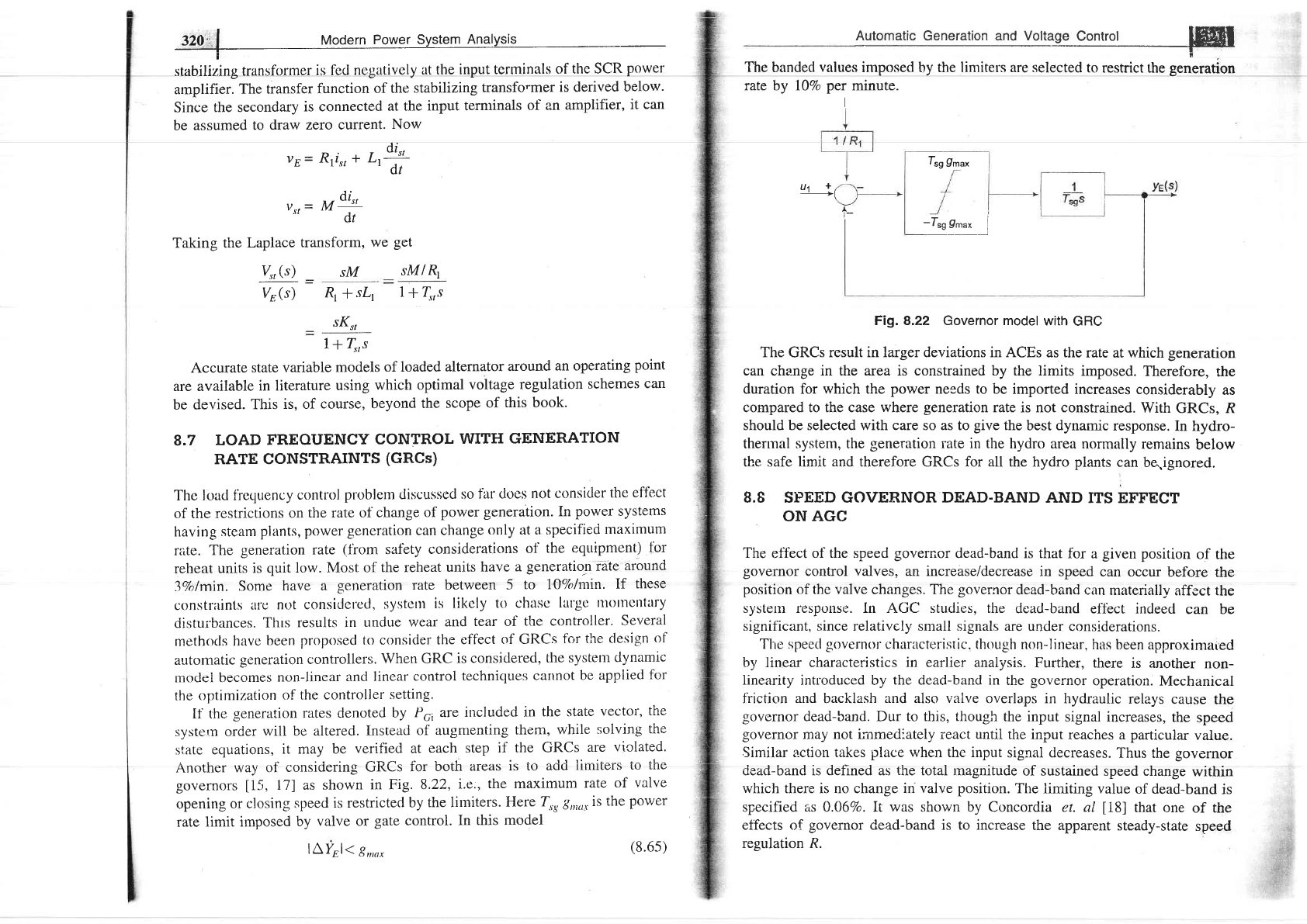
In this model
lAYEl.--
gu,nr
(8.6s)
Automatic
Generation and
Voltage
Control
Jffif
------_-----l
E
The banded
values
imposed hy the limiters are selected
to
resffict the
generation
rate by l}Vo
per
minute.
I
I.g
9t",
u't
+/
_+(
-t*9r"'--l
Fig.8.22 Governor model
with
GRC
The
GRCs
result in larger deviations in ACEs
as the rate
at which
generation
can
cha-nge
in the area is constrained by the limits
imposed.
Therefore,
the
duration for
which
the
power
needs to be imported increases
considerably
as
cornpared to the case where
generation
rate
is
not constrained.
With
GRCs, R
should be selected with care so as to
give
the best dynamic
response.
In
hydro-
thennal
system,
the
generation
rate in the
hydro area
norrnally
remains
below
the safe limit and therefore GRCs for all the hydro
plants
can
be.ignored.
8.8 SPEED GOVERNOR
DEAD-BAND
AND
ITS EFFECT
ON
AGC
The
eff'ect
of the speed
governor
dead-band is that
for a
given position
of the
governor
control valves, an increase/decrease
in speed
can occur
before
the
position
of the valve changes. The
governor
dead-band can
materially
affect the
system response. ln AGC studies, the
dead-band
eff'ect indeed
can
be
significant, since relativcly small signals are
under considerations.
TlLe speed
governor
characterristic. though
non-lirrear,
has been
approxinraaed
by linear
characteristics in earlier
analysis.
Further, there
is another
non-
iinearity
introduced by
the dead-band in
the
governor
operation.
Mechanical
f'riction
and
backlash
and
also
valve
overlaps
in hydraulic
relays
cause
the
governor
dead-band. Dur
to
this,
though
the input
signal
increases,
the
speed
governor
may not irnmediately react
until
the input
reaches a
particular
value.
Similar a.ction takes
place
when the input
signal decreases.
Thus
the
governor
dead-band is defined as
the
total rnagnitude
of sustained
speed change
within
which there is no change in
valve position.
The
limiting value
of dead-band
is
specified
as
0.06Vo. It
was
shown by Concordia et.
al
[18]
that one
of the
effects
of
governor
dead-band is to increase
the apparent
steady-state
speed
regulation R.
A
l-
lFFf
Modrrn Po*., svrt.t
Analuri,
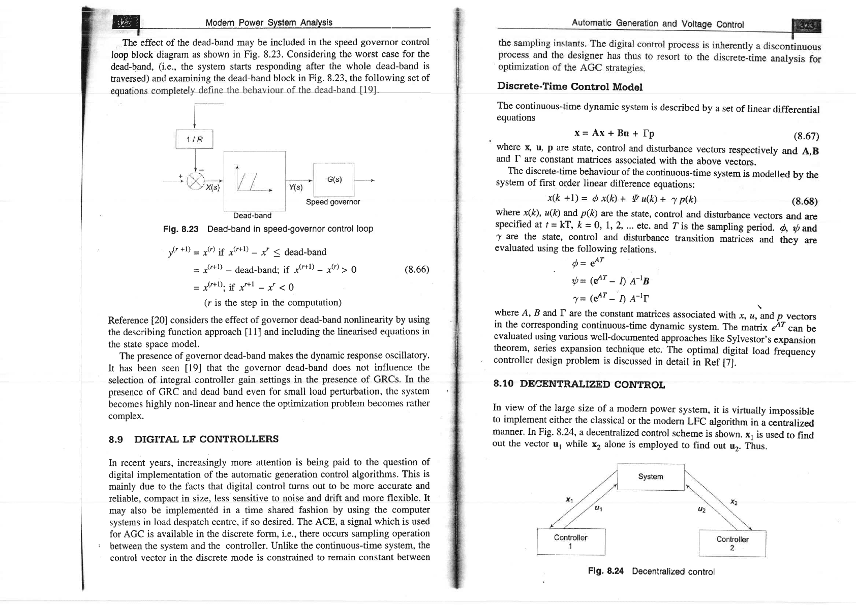
The
effect
of the dead-band
may be included in
the speed
governor
control
loop
block diagram
as shown
in Fig. 8.23.Considering
the worst
case forthe
dead-band,
(i.e.,
the system starts responding
after the whole
dead-band
is
traversed)
and examining
the dead-band block
in Fig.
8.23,the
following set
of
ly define the behaviourolthe
dead.band
[9]-
Speed
governor
Dead-band
Flg.
8.23
Dead-band
in speed-governor
control loop
u(r
+1)
=
7(r)
1:
"(r+1)
_
x,
1
dead-band
-
"(r+l)
_
dead-band;
if x('+l)
-
,(r)
I
g
-
"(r+1).
tf Xr*l
_
xt
<
0
(r
is the step in the
computation)
Reference
[20]
considers
the
effect of
governor
dead-band
nonlinearity
by using
the describing
function
approach
[11]
and
including the
linearised equations
in
the state
space
model.
The
presence of
governor
dead-band
makes the
dynamic response
oscillatory.
It has
been
seen
[9J
that the
governor
dead-band does not
intluence
the
selection
of integral
controller
gain
settings in the
presence
of GRCs.
In the
presence
of
GRC
and dead band even
for small
load
perturbation,
the
system
becomes
highly non-linear
and
hence the optimization
problem
becomes
rather
complex.
8.9
DIGITAL
LF CONTROLLERS
In recent
years,
increasingly
more
attention is
being
paid
to
the
question
of
digital implementation
of
the automatic
generation
control algorithrns.
This
is
mainly
due to the facts
that digital control
turns out to be more
accurate and
rcliqhlc nnrnnaef in
qize
less censifive to nnise end drift nnd more flexihle Tt
r v^rEv^vt
may also
be implemented
in a
time
shared fashion
by using the computer
systems
in load despatch
centre, if so desired.
The ACE,
a signal which is used
for AGC is
available in the discrete
form, i.e.,
there occurs sampling
operation
;
between the system
and
the controller. Unlike the
continuous-time
system, the
control vector in the discrete
mode
is constrained to
remain constant
between
(8.66)
Discrete-Time
Control
Model
The
continuous-time
dynamic
system
is described
by
a
set
of
linear
differential
equations
x=Ax+Bu+
fp
(8.67)
where
f
u,
P
are
state,
conhol
and
disturbance
vectors
respectively
and
A,B
and
f are
constant
matrices
associated
with
the
above
vectors.
The
discrete-time
behaviour
of the
continuous-time
system
is
modelled
by the
system
of
first
order linear
difference
equations:
x(k+1)=
Qx(k)+
Vu(k)+
jp&)
(8.68)
where
x(k),
u(k)
and
p(k)
are
the
state,
control
and
disturbance
vectors
and
are
specified
at t=
kr,
ft
=
0, 1,2,...
etc. and
ris
the
sampling
period.
6,
tl,nd
7
Te
the state,
control
and
disturbance
transition
matrices
and
they
are
evaluated
using
the
following
relations.
d=
eAT
{=({r_ln-tr
j=(eAr-DA-tf
where
A,
B and,
I
are
the constant
matrices
associated
with
r,
,,LO
p
vectors
in
the
conesponding
continuous-time
dynamic
system.
The
matri
x
y'r
can
be
evaluated
using
various
well-documented
approaches
like
Sylvestor's
expansion
theorem,
series
expansion
technique
etc.
The
optimal
digital
load
frequency
controller
design
problem
is
discussed
in
detail
in
Ref
[7].
8.10
DECENTRALIZED
CONTROL
In
view
of
the large
size
of a
modern power
system,
it is
virtually
impossible
to implement
either
the classical
or
the
modern
LFC
algorithm
in
a centralized
manner.
ln Fig.
8.24, a
decentralized
control
scheme
is
shown.
x,
is
used
to
find
out
the
vector
u, while
x,
alone
is
employed
to
find
out
u".
Thus.
Flg.
8.24
Decentralized
control