Kothari D.P., Nagrath I.J. Modern Power Systems Analysis
Подождите немного. Документ загружается.

564,'l
rr]logern
power
System
Analvsis
I
errrnrnorrinal Farrlt Analvsis I
geS
vyrrrrlvt"vE'
'|
--"
-"--
J
I
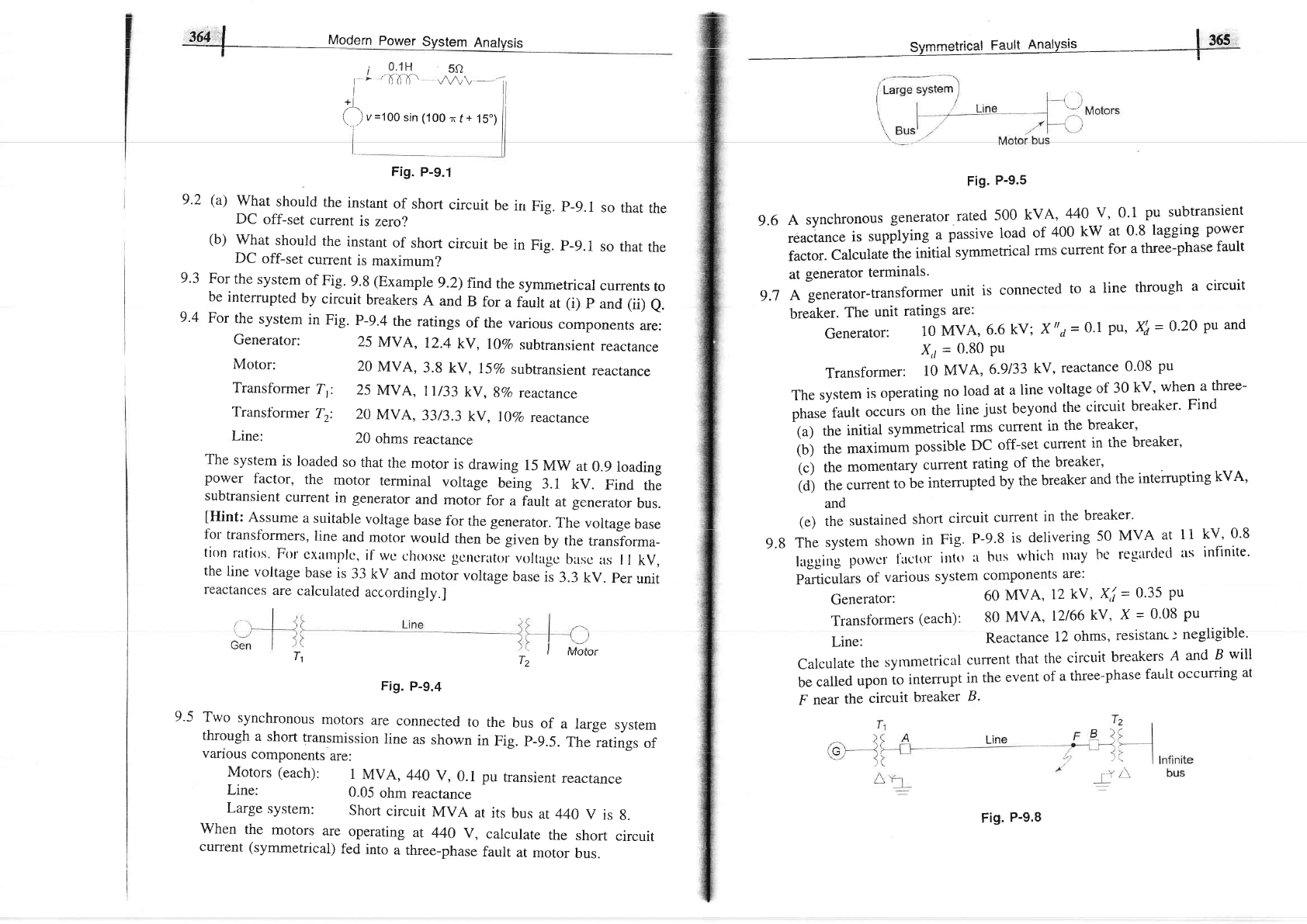
9.3
i
0.1H
SO
I
'
64-A-'
v^/v\
i
fl
u
=1OO
sin (100
n
f
+
15.)
Fig.
p-9.1
9 '2
(a)
What
should
the
instant
of short
circuit
be
in
Fig.
p-9.1
so
that
the
DC
off-set
current
is
zero?
(b)
what
should
the
instant
of
short
circuit
be
in
Fig.
p-9.1
so
rhar
the
DC
off-set
current
is
maximum?
For
the
system
of Fig.
9.8
(Example
9.2)
find
the
symmetrical
currents
to
be
interrupted
by
circuit
breakers
A
and
B
for
a
fault
ar
(i)
p
and
(ii)
e.
For
the
system
in
Fig.
p-9.4
the
ratings
of
the
various
componenrs
are:
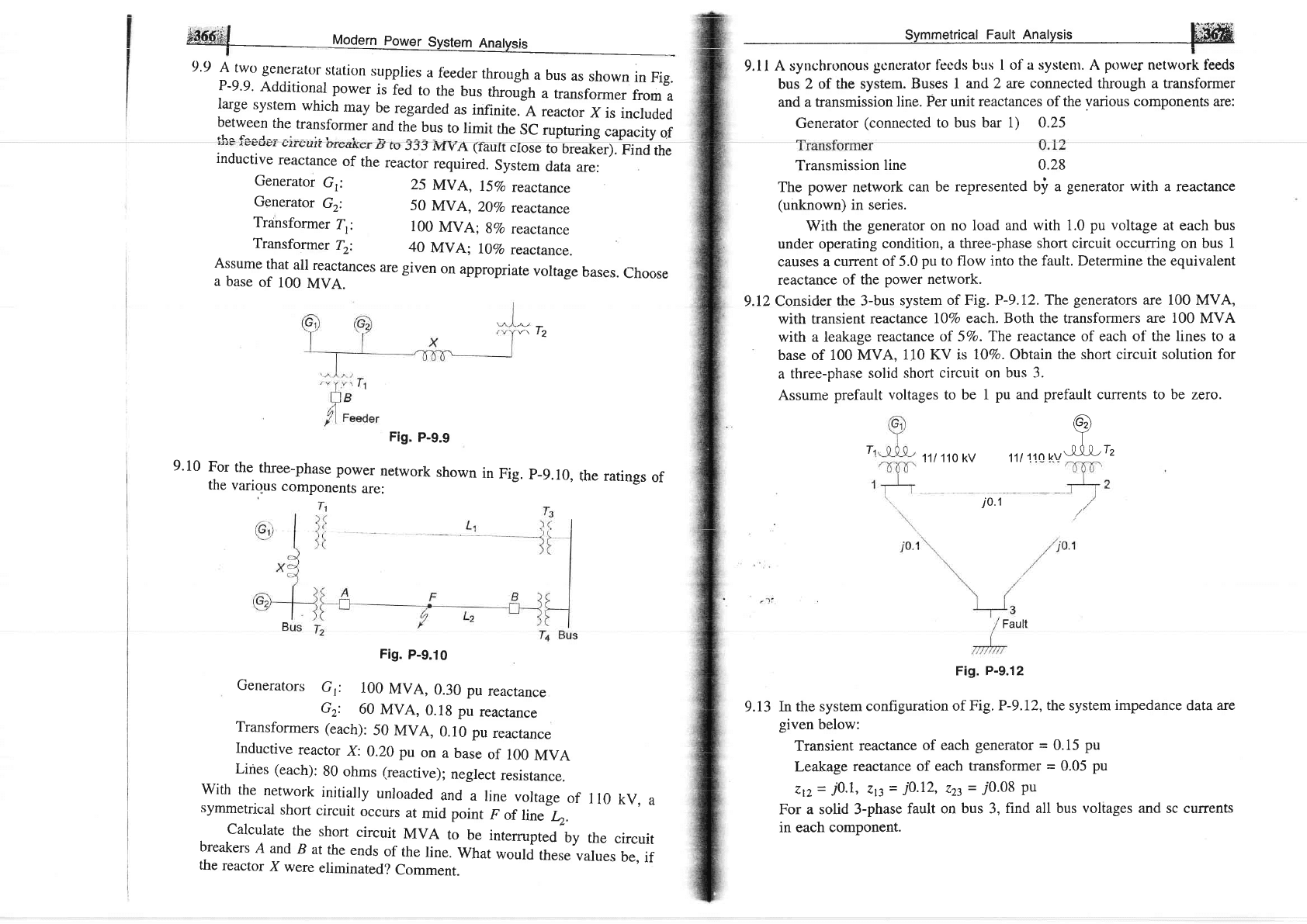
Fig.
P-9.5
Asynchronousgeneratofrated500kVA,440v,0.lpusubtransient
."u"'tun".
is
supptying
a
passive
load
of
400
kW
at
0.8
lagging
powel
factor.
Calculate
tfr"
in'itiui
symmetrical
rms
current
for
a three-phase
fault
at
generator
terminals.
A
generator-transformer
unit
is
connected
to
a
line
through
a
circuit
breaker.
The
unit
ratings
are:
Generator:
10
MVA,
6.6
kV;
X,,d=
0.1
pu, Xi=
o,2o
pu
and
X,r
=
0'80
Ptt
Transformer:10MVA,6.9133kV,reactance0.08pu
The
system
is
operating
no
load
at
a
line
voltage
of
30
kv,
when
a
three-
phase
tault
occurs
on
ih"
tin"
just
beyond
the
circuit
breaker'
Find
(a)
the
initial
symmetrical
rms
current
in
the
breaker'
iui
tt.
maximum
possible
DC
off-set
currenr
in
rhe
breaker,
(c)
the
momentary
current
rating
of the
breaker'
(d)
the
current,o
U.
intemrpted
by
the
breaker
and
the
intemrpting
kVA'
9.6
9.7
9.4
Generator:
Motor:
25
MVA,
12.4
kV,
l\Vo
subtransient
reactance
20
MVA,
3.8
kV,
l5%o
subtransient
reactance
Transformer
T,:
25
MVA,
11/33
ky,
gVo
reactance
Transfbrmer
Tr:
20
MVA,
33/3.3
kV,
I
\Vo
reactance
Line:
20
ohms
reactance
The
system
is loaded
so
that
the
motor
is
drawing
15
Mw
at
0.9
loading
power
factor,
the
motor
terminal
voltage
being
3.1
kv.
Find
the
subtransient
current
in generator
and
motor
for
a fault
at generator
bus.
lHint:
Assume
a
suitable
voltage
base
fbr
the
generator.
The
voltage
base
for
transformers,
line
and
motor
would
then
be given
by
the
transforma_
ti0n
rilti<ls.
Frlr
cxanrplc,
if'wc
choosc
gcrrcrator.
voltagc
basc
as
I
I
kv,
the
line
voltage
base
is
33
kv
and
motor
voltage
base
is
3.3
kv.
per
unit
reactances
are
calculated
accordingly.]
T
,1
T2
Fig.
p-9.4
Two
synchronous
motors
are
connected
to
the
bus
of
a
large
system
through
a
short
transmission
line
as
shown
in
Fig.
p-9.5.
The
ratings
of
vanous
components
are:
Motors (each):
1
MVA,
440
v,0.1
pu
transient
reactance
Line:
0.05
ohm
reacrance
Large
system:
Short
circuit
MVA
at its
bus
at 440
V
is
g.
when
the
motors
are
operating
at
440
v,
calculate
the
short
circuit
cuffent
(symmetrical)
fed
into
a
three-phase
fault
at
motor
bus.
and
(e)
the
sustained
short
circuit
current
in
the
breaker'
The
system
shown
in
Fig'
P-9'8
is
delivering
50
MVA
at
laggirrgp0w0rl.itctttrillttlltbrrswhichrtriryberegirrdecl
Particulars
of
various
system
components
are:
Generator;
60
MVA,
12
kV'
X,/
=
0'35
Pu
Transtbrmers
(each):
80
MVA,
12166
kV'
X
=
0'08
pu
Line:
Reactance
12
ohms'
resistanc:
negligible'
Calculate
the
syrnmetrical
current
that
the
circuit
breakers
A
and
B
will
be
called
upon
to
interrupt
in
the
event
of
a
three-phase
fault
occurring
at
F
near
the
circuit
breaker
B'
9.8
11
kv,
0.8
ils
infinite.
9.5
Line
Fig.
P-9.8
*Sf-,S
tgdern
power
Svstem
Anatvsis
t.-
9'9
A
two generatorstaticln
supplies
a
f'eeder
through
a bus
as
shown
in
Fig.
P-9'9'
Additional
power
is
fed
to
the
bus
throJgh
a
transfoilner
from
a
large
system
which
may
be
regarded
as
infinite.
A reactor
X
is
included
:,'jT:^"1^:t::1u1.',f"'Ter
and,1"-!T
to
limit
the
SC
rupruring
capacity
of
4v<rl\er
rr
ru
JJJ
rvtyA
(Iault
close
to breaker).
Find
the
inductive
reactance
of
the
reactor
required.
system
data
are:
-
bus
2 of the system.
Buses 1 and
2 are connected through a transformer
and a transmission
line. Per unit
reactances of the
various
components are:
Generator
(connected
to bus bar 1) 0.25
Transmission
line
0.28
The
power
network
can be
represented bi a
gene
ator
with
a reactance
(unknown)
in series.
With
the
generator
on no load
and
with
1.0
pu voltage
at each bus
under operating
condition,
a three-phase short circuit occurring on bus
1
causes
a current
of 5.0
pu
to flow
into the fault. Determine the equivalent
reactance of
the
power
network.
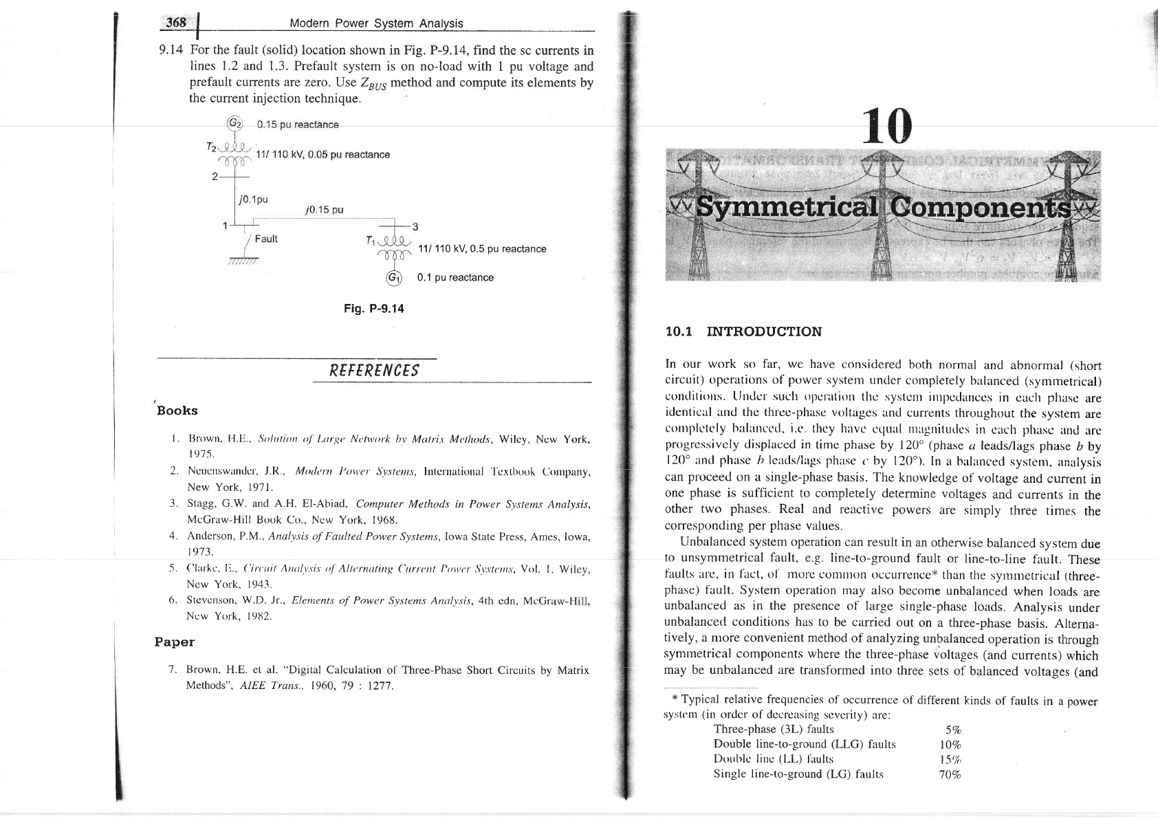
9.12
Consider
the 3-bus
system
of Fig. P-9.I2.
The
generators
are 100
MVA,
with transient
reactance
IjVo
each. Both the transforners
are 100
MVA
with
a leakage
reactance
of 5%t.
The reactance of each of the lines to
a
base of 100
MVA, 110
KV is 707o. Obtain
the short circuit solution for
a
three-phase
solid short
circuit on
bus
3.
Assume
prefault
voltages
to be
1
pu
and
prefault
currents
to
be zero.
Generator
Gr:
Generator
Gr:
Transformer
Tr:
Transformer
T2:
Assume
that
all
reactances
are
given
on
appropriate
voltage
bases.
choose
a
base
of
100
MVA.
ti
Tz
25
MVA,
757o
reactance
50
MVA,
20Vo
reactance
100
MVA;8Vo
reacrance
40
MVA;
l\Vo
reactance.
Fig.
p_9.9
9'10
For
the
three-phase
power
network
shown
in
Fig.
p-9.10,
the
various
components
are:
T1
11/
110 kV
G)
^T" T
f l
rn kv\-x-x-x-"
'2
the
ratings
of
j0.1
Fig.
p-9.10
Generators
Gr:
100
MVA,
0.30
pu
reactance
Gz:
60
MVA,
0.18
pu
reactance
Transformers
(each):
50
MVA,
0.10
pu
reactance
Inductive
reactor
X:
0.20
pu
on
a
base
of
100
MVA
Lines
(each):
80
ohms (reactive);
neglect
resistance.
with
the
network
initiaily
unroaded
and a
rine
vortage
of
110
kv,
a
symmetrical
short
circuit
occurs
at
mid point
F
of
rine
r-.
calculate
the
short
circuit
MvA
to
be
intemrpted
by
the
circuit
breakers
A
and
B
at
the
ends
of
the
line.
what
would
these
values
be,
if
the
reactor
X
were
eliminated?
Comment.
Fault
Fig. P-9.12
9.13
In the
system
configuration
of Fig.
P-9.12, the system
impedance
data
are
given
below:
Transient
reactance
of
each
generator
=
0.15
pu
Leakage
reactance
of each
transformer
=
0.05
pu
Ztz
=
i0.1,
zp
-
i0.12,
223
=
70.08
Pu
For
a solid 3-phase
fault on bus 3,
find all bus voltages and sc currents
in each component.
365
j
Modern
Power
System Analysis
t
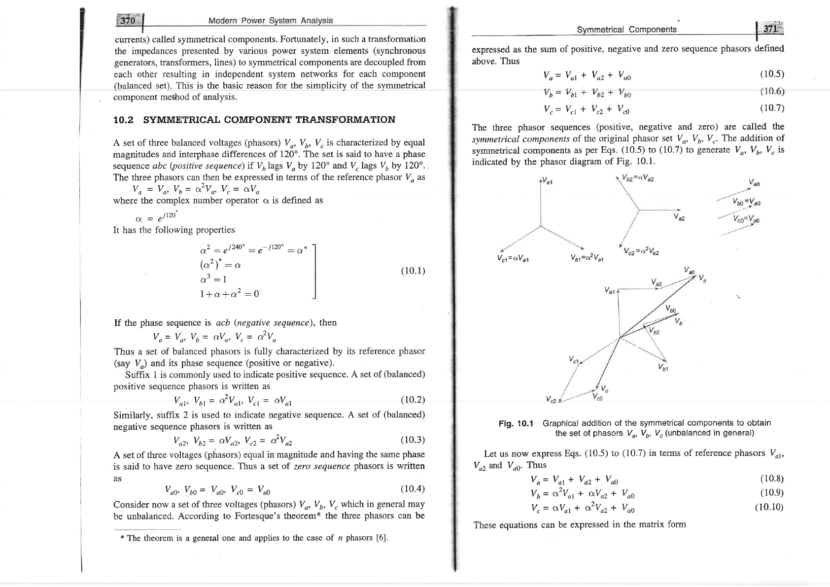
9.14
For the fault
(solid)
location shown
in Fig. P-9.I4, find
the sc currents in
lines 1.2
and 1.3. Prefault
system is
on no-load with 1
pu
voltage
and
prefault
currents are zero.
Use Zuu, method
and compute its
elements by
the
current injection technique.
'r-[b-
111
110
kV 0.5
pu
reactance
-l
Q9
0.1
pu
reactance
Fig. P-9.14
REF
ERE
N CE S
Books
l. BIrrwtt.
H.L).. Soltttiotr tt.f
I.ar,g,e Netwrtrk
lty
Mutrir Mctlutds, Wilcy,
Ncw York,
tL)'7 5.
2.
f.lctrcttswartdu',
j.it.,
Mtttit:t'tt
i'tnv'u'
5'vs'/ell,l, irrtcrrtatittrtaj
'i'cxtbook
eorrrplny,
New York,
1971.
'3.
Stagg,
G.W.
and A.H.
El-Abiad.
Computer
Methods in Power
Systems Analysis,
McCraw-Hill
Book
Co., Ncw York,
1968.
4. Anderson,
P.M., Analysis
of Faulted Power
Systems,Iowa
State Press, Ames, Iowa,
1973.
('frrt'kc.
l-,..
('in'ttit
Arrttl.t,,t'i,t o.f'Alttrnulitt,q
Ctrrrcrtl l'ttwrr S\,.r'/r,rl.r. Vol.
I,
New
York. 1943.
Stcvcrrson, W.D. Jr., Eletrrcnt.s
of Powcr
Systems Anuly-sis,4th
cdn, Mc(irz
Ncw
York, l9tl2.
Paper
"7.
Brown.
H.E. et al.
"Digital
Calculation
o[
Three-Phase
Short
Circuits by Matrix
Methods", AIEE Trani.,
1960, 79 :
1277.
10.1
INTRODUCTION
In
our work so far,
we
have considered
both
normal
and
abnormal
(short
circuit)
operettions of
power
systern
Llncler
cornpletely
balanced
(symmetrical)
colttlitiotts. LJlrrlcr suclt oltct'atiott
tltc systcrlr
irultcdanccs
in
caclr
phasc
are
identical
and the thrce-phase
voltages
and
currents
throughout
the
system
are
colltplctcly
hltlitncctl. i.c.
thcy huvc
crprirl
nurgrritutlcs
in
clrch
phusc
und
trc
prtrgrcs.sivcly
displaced
in
tirne
phase
by 120'
(phase
u leads/laes
phase
b
by
120'
and
phase
ir leads/llgs phitse
c
by
120").
In
a
b:rllnced
systenr,
lnalysis
can
proceed
on a single-phase
basis. The
knowledge
of
voltage
and
current
in
one
phase
is sufficient to
completely
determine
voltages
and
currents
in
the
other two
phases.
Real
and reetctive powers
are
simply
three
times
the
corresponding per phase
values.
Unbalanced system operation
can
result
in an
otherwise
balanced
system
due
to unsymmetrical
fault,
e.g. line-to-ground
fault
or
line-to-line
fault.
These
f'aults atrc, itt lhct,
ol' lnot'e conlnroll
occurrence+
thalt
the
syrnntetric:al
(three-
phase)
fault.
Systern operation
may also
become
unbalanced
when
loads
are
unbalanced as in
the
presence
of lar-ee
single-phase
loads.
Analysis
under
unbalancetl conditions
has to
be carried
out
on a three-phase
basis.
Alterna-
tively, a nlore convenient
method
of analyzing
unbalanced
operation
is
through
symtnetrical
components where
the
three-phase
voltages (and
currents)
which
may be unbalanced
are transfbrmed
into three
sets
of balanced
voltages
(and
*
Typical relative frequencies
of
occurrence
of
different
kinds
of faults
in a
power
syst(:llt
(irr
ordcr
ol' dccrcasing
scvcrity) are:
ll
I
-r.
6.
Three-phase
(3L)
faults
Double line-to-ground
(LLG)
faults
I)outrlc lirrc
(l-1,)
lirults
Single line-to-ground
(LG)
faults
5Vo
lj%o
|
5t/o
7jVo
currents)
called
symmetrical
components. Fortunately, in such a
transformation
the
impedances
presented
by
various power
system
elements
(synchronous
generators, transformers, lines) to symmetrical components
are decoupled from
each
other resulting in independent
system networks for
each component
anced set). This is the basic reason for the simolicitv of
the svmmetrical
component
method
of
analysis.
TO.2
SYMMETRICAL
COMPONENT TRANSFORMATION
A set of
three balanced voltages
(phasors)
Vo, V6, V"
is charactertzed by equal
magnitudes
and interphase differences of 120'.
The set is said to have a
phase
sequence abc
(positive
sequence)
if Vulags
Voby
l2O" and
V.
lags Vuby I20".
The three
phasors
can^then be expressed
in terms of the reference
phasor
Vo as
Vo
=
Vo,
V6
=
a"Va,
V,
=
aVo
where
the complex number
operator cr is defined as
sL
-
air20"
It has
the following
properties
symmetrica!
compo1gnlg
!
.a?.,{fi-i
above.
Thus
Vo--
Vot
* Voz
I Voo
(10.s)
b-
YbL-
vbz
Vr= VrI
*
Vrz * Vro
(
r0.7)
The
three
phasor sequences
(positive,
negative and
zero) are called
the
symmetrical
components
of the
original
phasor
set Vo, V6,V,. The
addition
of
symmetrical
components
as
per Eqs.
(10.5)
to
(10.7)
to
generate
Vo, Vr,
V, is
indicated
by
the
phasor
diagram
of
Fig. 10.1.
V61=crV61
V6fo?V11
Fig.
10.1 Graphical
addition
of the symmetrical
components to obtain
the set
of
phasors
V",
V6, V"
(unbalanced
in
general)
Let us
now
express
Eqs.
(10.5)
to
(10.7)
in terms
of
reference
phasors Voy
Vo2
and
Voe.
Thus
Vo=
Vot*
Vozl
Voo
Vu=
a.2Vor+
aVor* Voo
V"=
c-Vol+
o2vor*
Voo
These
equations
can
be
expressed
in the matrix
form
,*2:ei24o':e-ilAo"
_*
(o')*
:
o
a3
:l
l+ala2:0
(10.1)
(r0.2)
If the
phase
sequence
is acb
(.negative
sequence),
then
Vo=
Vo, Vu= tuVo, Vr= &Vo
Thus a set
of balanced
phasors
is fu'lly characterized
by its reference
phasor
(say
V,)
and its
phase
sequence
(positive
or
negative).
Suffix
1 is
commonly used to
indicate
positive
sequence.
A set of
(balanced)
positive
sequence
phasors
is written
as
Vo1, V61
-
&Vu1, Vrr
=
aVot
Similarly,
suffix 2 is
used to indicate
negative
sequence.
A set
of
(balanced)
negative
sequence
phasors
is written as
Vo2, V62= dVn2,
Vrz=
Q'Voz
(10.3)
A
set
of three
voltages
(phasors)
equal in magnitude and
having the same
phase
is said
to
have zero sequence.
Thus a set of
zero
sequence
phasors is written
AS
Vng, V6g
=
Vo1,
Vr1
=
Vo1
(10.4)
Consider
now
a set of
three voltages
(phasors)
Vo, V6,
V, which in
general
may
be
unbalanced.
According to
Fortesque's theorem*
the three
phasors
can
be
(10.8)
(10.e)
(10.10)
*
The theorem
is a
general
one and
applies to the case of
n
phasors
[6],
ffi#d
:
Modern Po*et
sytttt
Analysi,
-__r_-
and
Io
=
il'
where
I'
=
A-rI'
(10.19)
(10.20)
(10.21)
(r0.22)
(r0.23)
(ro.24)
(ro.2s)
(r0.26)
Vp
=
AV,
1,"1
v,
=
l'u |
=
vector
of original
Phasors
Lv, )
Iu'l
%
=
|
Voz
|
=
vector
of symmetrical
components
Lu"'.1
['
I
r-l
A
-1"
on
t
I
Ia
o2
t-l
We can
wrire
Eq.
(10.12)
as
V,
=
4-'V,
ComputinE ,{r and
utilizing
relations
(10.1),
we
get
[t
d
o']
o-'=*l
r
cr2
a
I
'Lt
r rl
In
expanded
form we
can
write Eq.
(10.14)
as
I
Vor
=
,<V"+
c-Vu+
a2VS
voz
=
!
fr"+
ozvu+
o%)
3
I
Vuo=
;
V,+
Vr,*
r,)
(10.11)
(10.12)
(10.13)
(10.14)
(r0.1s)
(10.16)
(10.17)
(10.18)
l
''l
[r,' I
Ir=lIu
l;ana
I,=lIo,
I
LI,)
Lr,o_i
Of course
A and A-r
are
the
same
as
given
earlier.
In expanded
form
the
relations
(10.19)
and
(10.20)
can
be
expressed
as
follows:
(i)
Construction
of current phasors
from
their
symmetrical
components:
Io=
Iot *
Ioz
*
Ioo
Ia=
o2lott
dozr
loo
Ir=
dot+
azlor*
Ioo
(ii)
Obtaining
symmetrical
components
of
current phasors:
1
Iot=
*
e"+
du+
o2lr)
;
t,r.=
i
(Io+
azlu+
aI,)
;.
Iro=,
Qo+
Iu+
Ir)
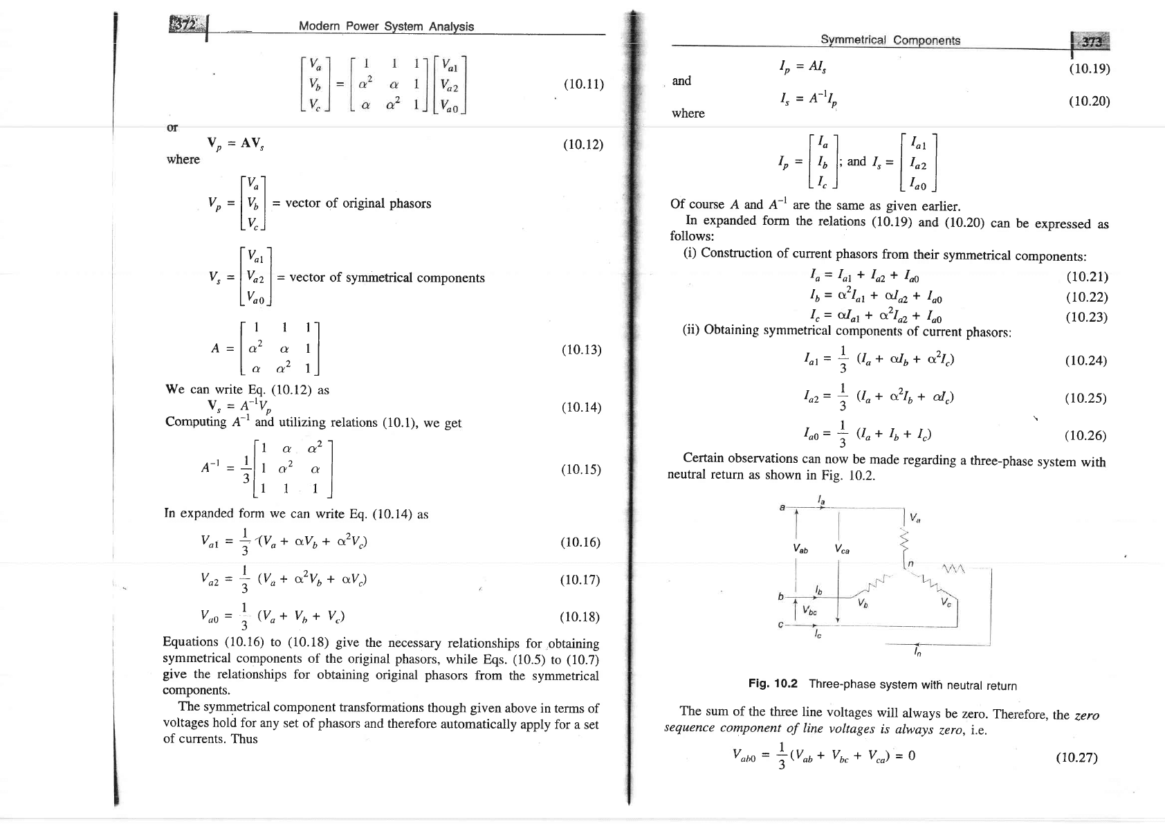
Certain
observations
can
now
be
made
regarding
a three-phase
system
with
neutral
return
as
shown
in
Fig.
10.2.
Equations
(10.16)
to
(10.18)
give
the
necessary
relationships
for
obtaining
symmetrical components
of the
original phasors,
while
Eqs.
(10.5)
to
(10.7)
give
the relationships
for
obtaining
original
phasors
frorn
the
symmetrical
components.
The
symmetrical
component
transformations
though
given
above
in terms
of
voltages
hold
for any
set of
phasors
and therefore
automatically
apply for a
set
of currents.
Thus
Fig. 10.2
Three-phase
system
with
neutral
return
The
sum
of
the three
line
voltages
will
always
be
zero.
Therefore,
the
zero
sequence
component
of line
voltages
is
always
zero,
i.e.
ln
Vao
V""
vobo
=
trr**
vu,+
v"o)
=
o
(10.27)
On the other hand, the
sum of
phase
voltages
(line
to neutral)'may not
be zero
so that their
zero sequence component
Vn, may
exist.
Since
the
sum of the three
line currents equals
the current in the
neutral
wire.
we have
(10.28)
i.e. the current in
the neutral is three
times the zerc sequence
line current.
If the
neutral connection is
severed.
Ioo=!U"+16+r")=!+
Ioo=lr,=o
3
t.e. in the
absence of a neutral connection
the
always
zero.
B
--_____}_----
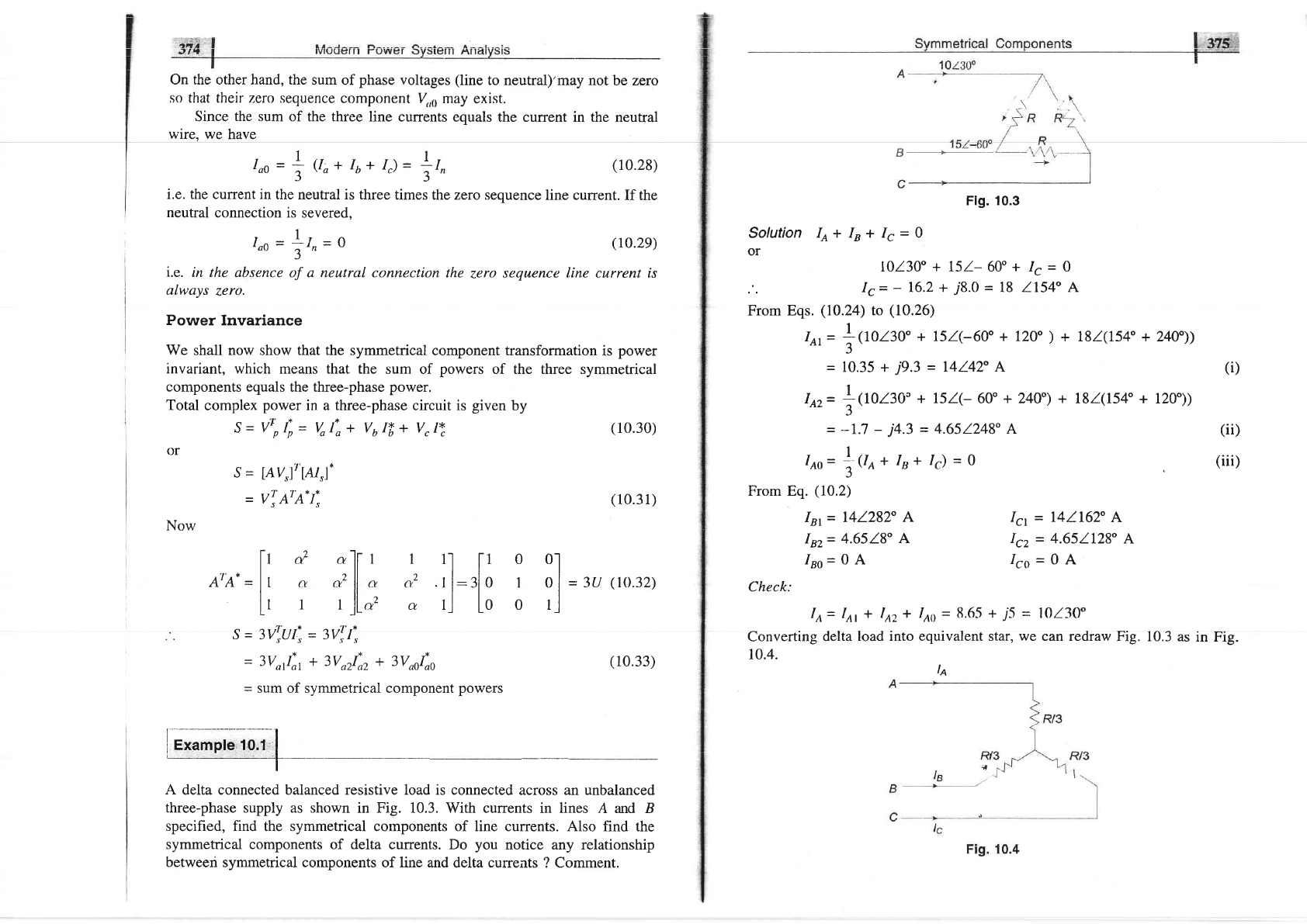
Flg. 10.3
Solution
Io + I" * Is
=
Q
or
10130"
+
l5l- 60o
+
Ic
=
O
Ic=
-
16.2 +
j8.0
=
18
1154"
A
(ro.2e)
zero
sequence line
current is
(10.31)
From
Power Invariance
We
shall now show that the symmetrical
component transformation
is
power
invariant, which
means that the
sum of
powers
of the three symmetrical
components equals
the three-phase
power.
Total
complex
power
in a three-phase circuit is
given
by
S=fp$=
41,+
Vutt+ V,t!
(10.30)
or
s
=
[A
v,,]'t'lAl,l.
=
v! 'qr'q. tI
Now
[r
o? 'Tt
o16.=lt
a
"tll
a
[r
r
I
JLa,
..
s=31yti,=341.,
(10.33)
A
delta connected balanced resistive load
is
connected
across an unbalanced
three-phase
supply as shown in Fig. 10.3. With currents
in lines A and B
specified, find
the symmetrical components of line currents. Also
find the
symmetrical components
of delta currents. Do
you
notice any relationship
betweeri
symmetrical components of line
and delta currents ? Comment.
Eqs.
(10.24)
to
(10.26)
1
Itr=
:0Ol3O"
+ 751(-60" + l2O"
)
5
=
10.35 +
j9.3
=
14142"
A
+ I8l(154" + 240"))
(i)
151(-
60o
+ 240") +
I8l(154' + 120"))
4.651248" A
(ii)
/c)
=
0
(iii)
I
Iez=
;Q0130'
+
J
=
--1.7 -
j4.3
=
I
Iao=
t^
(lo
+ IR
+
J
From Eq.
(10.2)
Im= 141282"
A
Inz= 4'6518"
A
Iao=oA
r
rl
l-1
0 0l
n'
.rl:r|o
r ol-t,
(10.32)
c-llL00ll
Icr
=
141162"
A
Icz
=
4.651128" A
Ico=oA
Check:
Ia= Iat * I,rz*
I,to
=
8'65 +
j5 =
10130"
Converting
delta load
into equivalent star,
we
can redraw
Fig. 10.3
as in Fig.
10.4.
la
=
3V^1, +
3V"r!),
+
3V"oI),
=
sum of symmetrical component
powers
I
Example 10.1
|
-T
_\
$,$i.M
Modern
power
system anatysis
I
Delta
currents are obtained as follows
Qrrmmatriaal l-amnnnanla tffiffi
Positive
and negative sequence voltages and currents
undergo
a
phase
shift
in
passing
through
a star-delta transformer which
depends
upon
the labelling
of
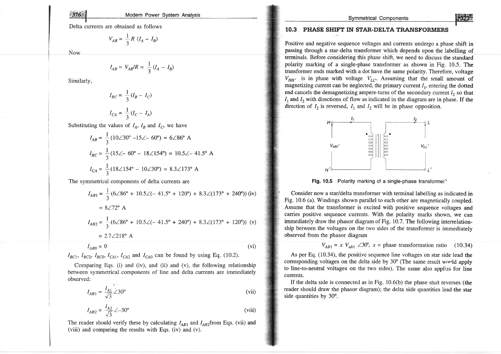
terminals. Before considering this
phase
shift, we
need
to discuss
the standard
polarity
marking of a single-phase transformer
as shown
in Fig. 10.5.
The
transformer ends
marked
with a dot
have the same
polarity.
Therefore, voltage
Vun,
is in
phase
with
voltage
V..,. Assuming
that the
small amount
of
magnetizing
current can be neglected, the
prirnary
current
1r, entering
the dotted
end cancels
the demagnetizing ampere-turns
of the secondary
current 1,
so that
I, and
12 with directions
of flow
as indicated
in the
diagram are in
phase.
If
the
direction
of 1, is reversed, 1, and 1, will
be in
phase
opposition.
veB=
Io
U^-
Ir)
ItB=
zAB)R
-
tUo-
ru)
Similarly,
rnc=
Ier-
Ir)
5
Ice=
!frr-
Io)
5
Substituting the values
of
Io,
Iu and Ir,
I
en
=
!
Oozzo"
-r5l-
60")
=
rnc=
lOsz-
60"
-
rllr54")
rcn=
!W2154"
-
rol3o")
=
we have
6186 A
=
lO.5l-
41.5"
A
8.31173"
A
The symmetrical components
of delta currents are
1
Iem=
;(6186"
+
IO.5l(- 4I.5'+
l2O")
+
8.31(173"
+ 240"))(iv)
J
=
8172" A
I
I,qaz=
:6186"
+
1051(- 41.5" + 240") + 8.31(173" + 120"))
(v)
J
=
2.71218" A
Ieno= 0
Incr,
Ircz, IBC,,lsn1, Iga2 and 1.oo can be found by using Eq.
(10.2).
Comparing
Eqs.
(i)
and
(iv),
and
(ii)
and
(v),
the following relationship
between
symmetrical
components
of line and delta currents are immediately
observed:
t'
IeBr=
+130"
(vii)
VJ
Ienz=
\
z-zo"
(viii)
!J
The reader should
verify
these
by calculatrng Io', and
l*2from Eqs.
(vii)
and
(viii)
and
comparing the
results
with Eqs.
(iv)
and
(v).
Flg. 10.5 Polarity marking
of a single-phase
transformer\
Consider now a star/delta transformer with
terminal
labelling
as indicated
in
Fig. 10.6
(a).
Windings
shown
parallel
to each
other are
magnetically
coupled.
Assume
that the
transformer is excited with
positive
sequence voltages
and
carries positive
sequence
currents. With the
polarity
marks
shown, we
can
immediately
draw the
phasor
diagram of
Fig. 10.7.
The following
interrelation-
ship
between the voltages
on
the two
sides of
the transformer
is immediately
observed
from the
phasor
diagram
VtBt= x Vabr
l3V, -r
-
phase
transformation
ratio
(10.34)
As
per
Eq.
(10.34),
the
positive
sequence line
voltages
on star
side lead
the
corresponding voltages
on the delta side by
30"
(The
same result wo,'ld
apply
to
line-to-neutral
voltages
on
the two sides).
The
same also applies
for
line
currents.
If the
delta side is connected as in Fig.
10.6(b) the phase
shrft reverses
(the
reader should
draw the
phasor
diagram); the
delta side
quantities
lead the
star
side
quantities
by 30".
(vi)
A
__--______
ar
System Analys'is
Symmetricat
Componentg
|
3?9
I
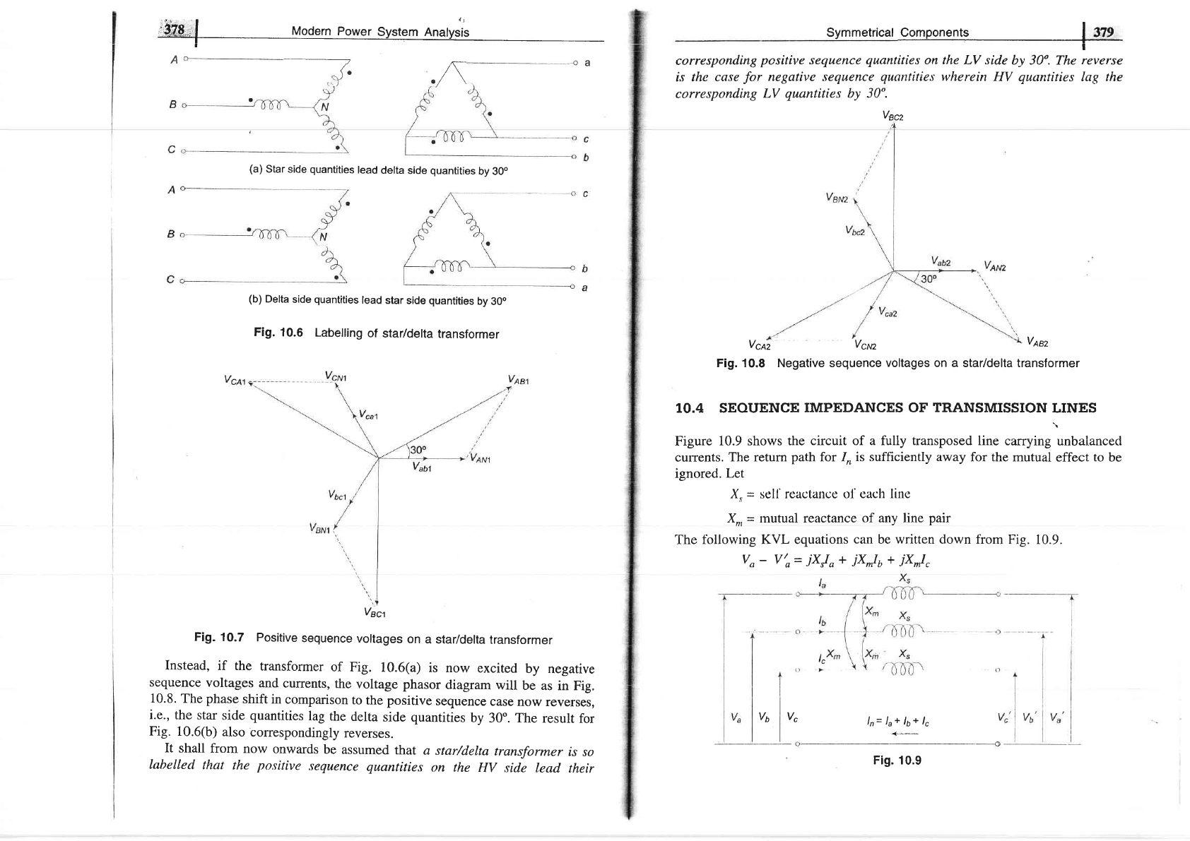
correspotxding
positive
sequence
quantities
on the LV side
by 30'. The
reverse
is the
case
for
negative sequence
quantities
wherein
HV
quantities
lag the
corresponding
LV
quantities
by 30".
vsc2
l-
/\
oa
(a)
Star
side
quantities
lead
delta
side
quantities
by
30o
(b)
Delta
side
quantities
lead
star
side
quantities
by
30o
Fig.
10.6
Labelling
of
star/delta
transformer
Fig.
10.7
Positive
sequence
voltages
on
a star/delta
transformer
Instead,
if the
transformer
of
Fig.
10.6(a)
is now
excited
by
negative
sequence
voltages
and
currents,
the
voltage phasor
diagram
will
be
as in Fig.
10.8.
The phase
shift
in
comparison
to the positive
sequence
case
now reverses,
i.e.,
the
star
side
quantities
lag the
delta
side
quantities
by
30'.
The
result for
Fig.
10.6(b)
also
correspondingly
reverses.
It shall
from now
onwards
be
assumed
that
a
star/delta
transformer
is
so
labelled
that
the
po,sitive
sequence
quantities
on the
HV
side lead
their
vcea
Vcrcz
Vesz
Fig. 10.8 Negative sequence
voltages on a
star/delta transformer
IO.4 SEOUENCE
IMPEDANCES OF
TRANSMISSION
LINES
Figure
10.9 shows the
circuit of a fully transposed line
carrying unUalancecl
currents.
The
return
path
for 1,,
is sufficiently away
for the mutual
effect
to
be
ignored. Let
X"
=
sell'reactance
o1'each line
X.
=
mutual reactance
of any line
pair
The
fbllowing KVL equations
can
be written down from
Fig. 10.9.
Vo
-
V'o=
jXJo
+
jX*Iu
+
.ixmlc
lr= l"+ lo+ 1"
-(-
V6
Vec'l
vc
Fig. 10.9
Modern
PgwgfSy$gln
Snalysis
Svmmetrienl cnmnonent( tflIlFffi
T
t,
Z1 12 22
o-------{__]-
-o
"----f--}-
---o
4
-
r[:
jxJo
l',
-
V!:
iXJ"
or in rnatrix
form
+
jxh
+ jx*["
+ jxmlb
+ jxJ"
(10.3s)
(10.36)
(10.37)
(10.38)
(10.3e)
(10.40)
(r0.42)
(10.43)
(r0.44)
(10.4s)
(or
negative)
(a)
Positive
sequence
network
(b)
Nagative
sequence
network
ls
Zs
o---)--f---_l.-
@)Zero
sequence
network
^a
Ib
I"
vI
vi
vb
v"
I//
-
--
/
n-
v!):
r//
-
-
,'s-
V,
r
=J
x^x,x.
x_x*x,
or A
(I/,
-
or
v,
Now
A-I ZA
:
0
X,-X*
0
zt00
0220
00zo
wherein
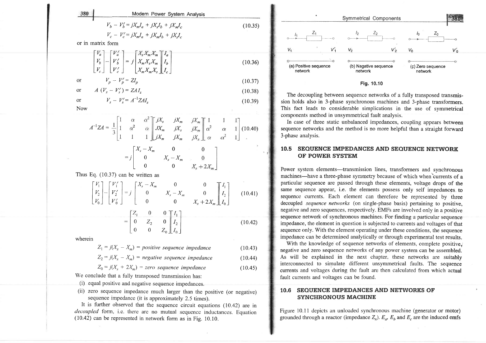
Zr:
j(X,
-
X,r)
:
positive
sequence
impedance
Zz:
j(X,
-
X^)
:
negative
sequence
impedance
Zo:
i(X,
+
2X)
:
zero
,tequence
impedance
We conclude
that
a
fully transposed
transmission
has:
/t;\ o^rrol ^^o.i+i"o ^-l -^^^+i --^:^-^)^-^^-
\r,,
vyuar
pvrrlryu
(trlrl
ut/ts4Lrvg
strqu{rrruE
rrup€uallutis.
(ii)
zero
sequence
impedance
much larger
than
the positive
Fig.
10.10
The decoupling between sequence
networks of
a fully transposed
transmis-
sion holds also in
3-phase
synchronous
machines
and
3-phase transformers.
This fact leads to considerable
simplications in
the use
of symmetrical
components
rnethod in unsymmetrical
fault analysis.
In case
of three static unbalanced impedances,
coupling
appears between
sequence networks and the method is
no more helpful
than
a straight forward
3-phaso
unalysis.
10.5
SEQUENCE
IMPEDANCES
AND
SEOUENCE
NETWORK
OF
POWER
SYSTEM
Power system slernsnfs-transmission lines,
transformers
and.
synchronous
nlachines-have
a three-phase symmetry because
of
which when'currents
of
a
particular
sequence are
passed
through
these elements,
voltage
drops of
the
same sequence
appear, i.e. the elements
possess
only self
impedancos-
to
sequence
currcnts. Each eleurent
can therelbre
be represented
by tlree
decoupled sequence networks
(on
single-phase
basis)
pertaining
to
positive,
negative and zero sequences, respectively.
EMFs
are involved
only
in a
positive
sequence network of synchronous machines.
For finding
a
particular
sequence
impedance, the
element
in
question
is subjected to
currents
and voltages
of
that
sequence
only.
With the element operating
under these
conditions,
the sequence
impedance can be determined analytically or through
experimental
test
results.
With the knowledge of sequence networks
of
elements,
complete
positivel'
negative and
zero sequence networks of any
power
systern
can be assembled.
As will be explained in
the next chapter.
these
networks are suitably
interconnected to simulate
different unsymmetrical
faults. The
sequence
currents
and voltages during the
fault are
then calculated
from
which actual
far"rlt
currents and
voltases can be found.
10.6 sEQuENCg
I;IpTDANCES AND NETWoRKs
oF
SYNCHRONOUS
MACHINE
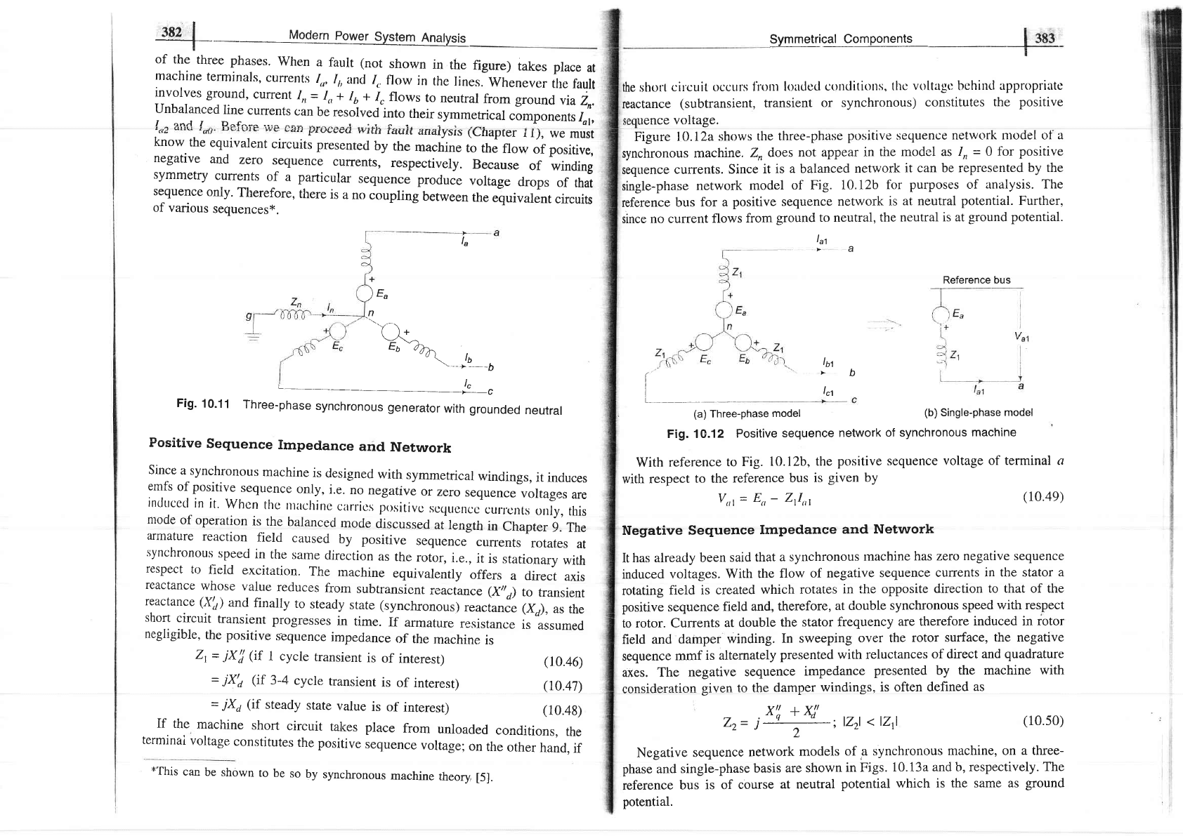
Figure
10.11 depicts
an unloaded
synchronous rlachine
(generator
or motor)
grounded
through
a reactor
(impedance
Z).8o, E6and E, are the induced emfs
zIo
zuIs
A-IZAI,
jx,
JX^
jx^
jx^
jx,
jx^
l*,
-
',
:J
L
:
Thus
Eq.
(10.37)
can
be written
as
|
41
l'tr( I I
x"-
x^
l"l-l't l:'I
o
LrroJlrrtJ
L
o
0
o
ll-r, I
x,
-
x,,,
o
ll
r,
|
(l
o.4l)
o
x,
*zx^
)j,l
l[
/'
.l
ll
,,
I
lLr, i
sequence
impedance (it
is approximately
2.5 times).
It
is further
observed
that
the
sequence
circuit
equations
(10.42)
are
in
decouplecl
fbnn,
i.c.
thcrre
arc
no
rnutual
scqucncc
inducternccs.
F)quation
(10.42)
can be
represented
in
network
form as
in Fig.
10.10.
3S2
I
_
Modern
power
System
Anatysis
--]-
of
the
three
phases.
when
a fault (not
shown
in
the
figure)
takes
place
at
machine
terminals,
currents
1,,,
I,,and
/.
flow
in
the
lines.
whenever
the
fault
involves
ground,
current
In=
In+
Iu
+
^I"
flows
to
ne'tral
from
ground
"i^I^'.
negative
and
zero
sequence
culrents,
respectively.
Because
of
winding
symmetry
currents
of
a particular
sequence
produce
voltage
drops
of
that
sequence
only.
Therefore,
there
is
a no
coupling
between
the
equivalent
circuits
of
various
sequences*.
uence
voltage.
Hrvvvvs
yyrrrr
r(rLrll
4rr.1IyJIs
(\_napler
i l),
we
must
know
the
equivalent
circuits
presentecl
by
the
*u.hin"
to
the
flow
of positive,
Symmetrigel_qg4pe!e$s
_
the short
circuit occurs
lirrnr
kradccl
conditiorts,
thc
voltagt:
behind
appropriltc
reactance
(subtransient,
transient
or synchr:onous)
constitutes
the
positive
Figure
lO.IZa
shows
the three-phase
positive sequence
network ntodel
of a
synchronous
machine.
Z,
does
not appear
in
the model as
Iu
=
0 for
positive
sequence
currents.
Since
it
is a balanced
network
it
can be represented
by the
single-phase
network
model
of Fig.
10.12b
for
purposes of analysis.
The
reference
bus
for a
positive sequence
network
is
at neutral
potential.
Further,
since
no current
flows
from
ground to neutral,
the neutral
is at
ground potential.
lat
>a
(
I
I
I
(a)Three-phase
model
Fig. 10.12
Positive
sequence
network
of synchronous
machine
With
reference
to
Fig.
10.12b,
the
positive sequence
voltage of terminal c
with respect
to the reference
bus
is
given
by
V,,l=
E,,- Zll,,l
(10.4e)
Negative
Sequence
Impedance
and
Network
It
has already
been
said
that
a synchronous
rnachine
has zero
negative sequence
induced
voltages.
With
the
flow
of negative
sequence
currents
in the stator
a
rotating
field
is created
which
rotates
in the opposite
direction to that
of
the
positive
sequence
field and,
therefore,
at double
synchronous
speed
with respect
to
rotor. Currents
at double
the stator
frequency
are therefore
induced in rotor
field
and
damper
winding.
In sweeping
over the
rotor surface,
the negative
sequence
mmf
is alternately
presented with reluctances
of direct and
quadrature
axes.
The
negative
sequence
impedance
presented by
the machine with
consideration
given to the
damper
windings, is often defined
as
la
-*
)e"
.n
'-----
(
t+
\=\'-..
t:.6
d-n>_
-u
\
t6
-->
-----b
L-----
____l_"
Fig'
10'11
Three-phase
synchronous
generator
with
grounded
neutral
Positive
Sequence
Impedance
and
Network
Since
a synchronous
machine
is
clesigned
with
symmetrical
windings,
it
induces
emfs
of
positive
sequence
only,
i.e.
no
negatrve
or
zero
sequence
voltages
are
incltrced
in
it'
Whcn
thc
tttltcltinc
currics
positivc
scqucncc
curr.cnts
glly,
this
ntode
of
operation
is
the
balanced
mocle
discussed
ailength
in
Chapter
9. The
armature
reaction
field
caused
by
positive
sequence
currents
rotates
at
'synchronous
speed
in
the
salne
clirection
as
the
,otu.,
i.e.,
it
is
stationary
with
respect
to
field
excitation.
The
machine
equivalently
offers
a
direct
axis
reactance
whose
value
reduces
from
subtransicnt
reactance
(X,a)
to
transient
reactance
(Xtr)
and
finally
to
steady
state
(synchronous)
reactanJe (Xa),
as
the
short
circuit
transient
progresses
in
time.
If
armature
resistance
is
assumed
negligible,
the positive
sequence
impedance
of
the
machine
is
ln't
,b
lc't
Reference bus
(b)
Single-phase
model
21=
jXtj
(if
I cycle
transient
is
of
interest)
=
jX'a
Gf
3-4
cycle
transient
is
of
interest)
=
jXa
(if
steady
state
value
is
of
interest)
xt:
+
x,!
Z.t=
j
;lZ2l<lZrl
2
(10.46)
(10.47)
(10.48)
If
the
machine
short
circuit
takes
place
from
unloaded
conditions,
the
terminai
voltage
constitutes
the
positive
sequence
voltage;
on
the
other
hand.
if
Negative
sequence
network
models
of a synchronous
machine, on
a three-
phase
and
single-phase
basis
are shown
in Figs.
10.13a
and b, respectively.
The
reference
bus
is of
course
at neutral
potential which
is
the same as
ground
potential.
(10.s0)
*'fhis
can
be
shown
to
be
so
by
synchronous
machine
theory,
[5].