Kothari D.P., Nagrath I.J. Modern Power Systems Analysis
Подождите немного. Документ загружается.

Modern
Power
System
Anatysts
The
circuit
model
for
the
system
of
Example
9'3
for
computation
of
postfault
condition
is
shown
in
Fig'
9'14'
_
0.9636x
70.60
=
-
78.565
pu
Change
in
generator
current
due
to
fault'
AI^=- l8.s6s
t
io'+
-
-
i2'141
Pu
,,
B
_
r"."
"_
j0.60
Change
in
motor
current
due
to
fault'
At^=-
78.565
x
j.$*i
--
-
i6'424
Ptt
To
these
changes
we
add
ttre
prefault
current
to
obtain
the
subtransient
current
in
machines.
Thus
I'l=
I"
+
AIr
-
(0.623
-
j1.67$
Pu
In
=
-
I"
+
AI^=
(-
0.623
-
76.891)
Pu
which
are
the
same
(and shoutd
be)
as
calculated
already
we
have
thus
solved
Example
9.3
alternatively
through
th9
Thevenin
theorem
ond
,up.rposition.
This,
in4eecl,
is
a
powerful
method
for
large
networks.
9.5
SELECTION
OF
CIRCUIT
BREAKERS
.Iwootthccircuitbrcakcrratingswhiclrrcc;uircthcctrnlptlttttionofSCcurrent
are:
rated
momentary
current
and
rated
symmetrical
interruptirtg
c:nrrent'
Syrnmetrical
SC
current
is
obtained
by
using
subtransient
reactances
for
synchronous
rnachines.
Momcntary
current
irms)
is
then
calculated
by
multiplying
the
symmetrical
-o-"nory
current
by
a
factor
of
1'6
to
account
for
the
presence
of
DC
off-set
current'
Symmetrical
current
to
be
intcrrupted
is
computed
by
r'rsing
subtransient
reactances
tor
synchronous
generators
and
transient
reactances
for
synchronous
motors-induction
motors
are
neglected*.
The
DC
off-set
value
to
be
added
to
obtain
the
current
to
be
interrupted
is
accounted
for
by
multiplying
the
symmetrical
SC
current
by
a
factor
as
tabulated
below:
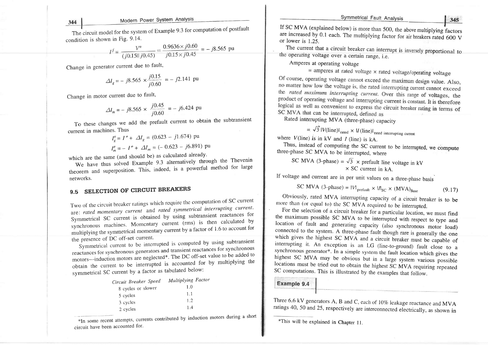
Multiplying
Factor
,Qrrrnmalrinal E^..t+ A --r. --!-
If
sc
MVA (explained
below)
is
more
than
500,
the
above
multiplyingiactors
are
increased
by
0.1
each.
The
multiplying
factor
for
air
breakers
rated
600
v
or
lower
is
1.25.
The
current
that
a
circuit
breaker
can
intemr
rng
voltage
over
a certain
range,
i.e.
Amperes
at
operating
voltage
Rated
intemrpting
MVA
(three-phase)
capacity
=
'6ty(tifle)lrated
x
11(line)lrated
inremrpting
cunent
where
V(line)
is in
kV
and
1
(line)
is
kA.
Thus,
instead
of_computing
the
sc
current
to
be
intemrpted,
we
cbmpute
three-phase
SC
MVA
to
be
intemrpted,
where
r
--'
'
SC
MVA
(3-phase)
_
Jt
x
prefault
line
voltage
in
kV
x
SC
current
in
kA.
If
voltage
and
current
are
in per
unit
values
on
a three-phase
basis
SC
MVA
(3-phase)
=
lylp,..roul,
x
11116
x (MVA)uur.
(e.r7)
Circuit
Breaker
SPeed
8
cycles
or
slower
5
cycles
3
cyclcs
2
cycles
attempts,
currents
contributed
accounted
for.
1.0
1.1
1.2
1.4
by
induction
motors
during
a
short
Ohviorrslrr rqf oA l\/\/ A i-+^*,--.:- - - -'-'L'Yru'uJrJ'
iciiuu
lvtvA
inieirupiiilg
capaclty
of
a
circuit
breaker
is
to
be
rnurc
thln
(or
cclual
to)
thc
sc
MVA
required
to
be
intemupted.
For
the
selection
of
a
circuit
breaker
for
a particular
location,
we
must
find.
the
maximum
possible
SC
MVA
to
be
intemrpted
with
respect
to
type
and
location
of
fault
and
generating
capacity
(also
synchronous
rnotorl
load)
connected
to
the
system.
A
three-phase
fault
though
rare
is
generally
the
one
which
gives
the
highest
SC
MVA
and
a
circuit
breaker
must
be
capable
of
interrurpting
it.
An
exception
is
an
LG
(line-to-ground)
f.ault
close
to
a
synchronous
generator*.
In
a
simple
system
the
fault
location
which
gives
the
highest
sc
MVA
may
be
obvious
but
in
a
large
system
various
possible
locations
must
be
tried
our
to
obtain
the
highest
st
nava
requiring
Lp"ur"a
SC
computations.
This
is
ilustrated
by
the
examples
that
follow.
Iii"'n"
r.;
I
Three
6.6
kv generators
A,
B
and
c,
each
of
I0o/o
leakage
reactance
and
MVA
ratings
40,
50
and
25,
respectively
are
interconnected
electrically,
as
shown
in
t'In
some
recent
circuit
have
been
tThis
will
be
explained
in
Chapter
1 l.
15:!"'l
.";: I
{d46..t|
Modern
Power
System
Analysis-
T
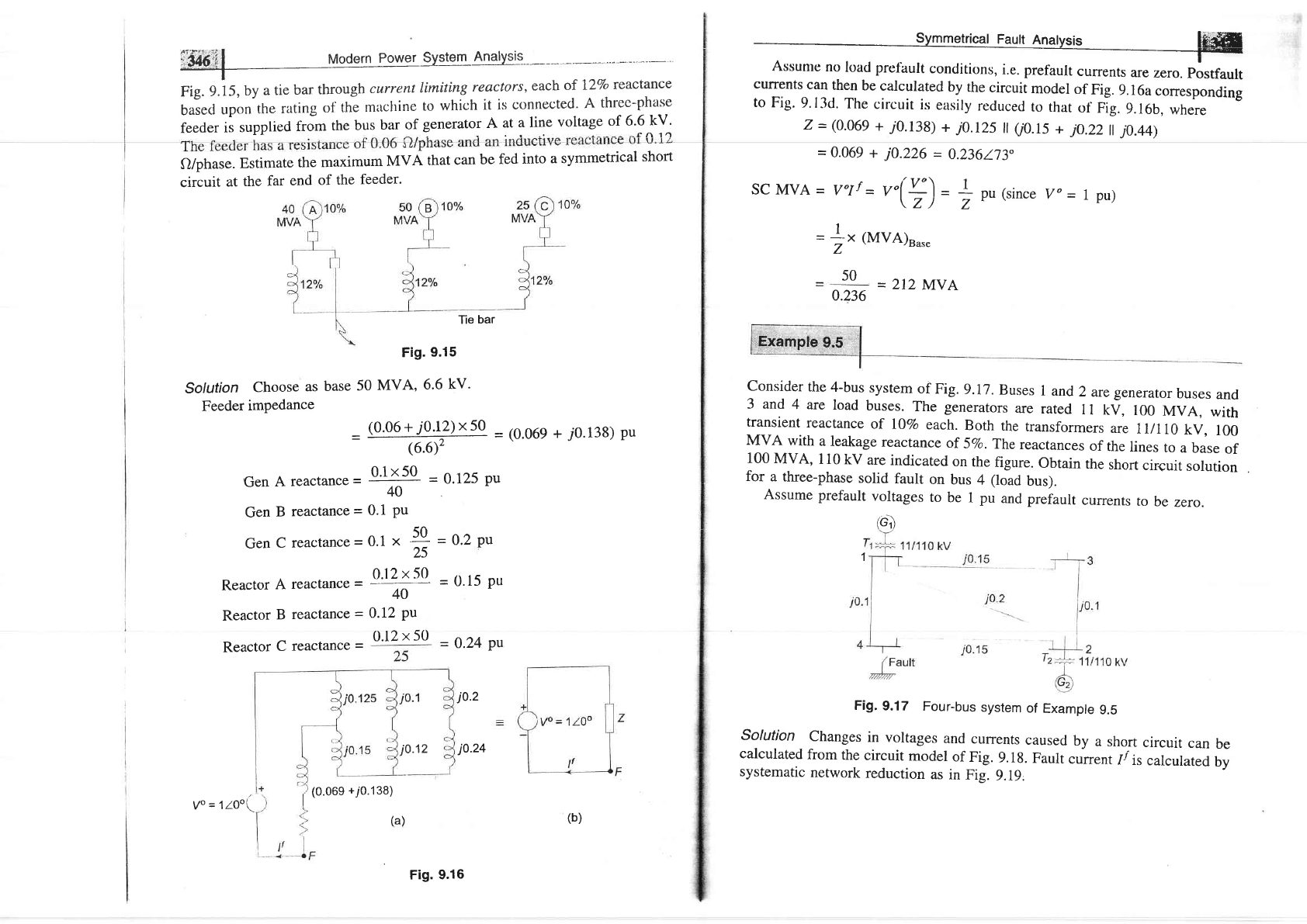
Fig.
f.i5,
by
a tie
bar
through
curent
timiting
reactors,
each
of
I2Vo
reactance
baiecl
upon
the
rating
ofthe
machine
to
which
it
is
connected.
A
threc-phase
feeder
is
supplied
from
the
bus
bar
of
generator
A
at
a line
voltage
of
6'6
kV'
^f n 1a
Q/phase.
Estimate
the
maximum
MVA
that
can
be
fed
into
a symmetrical
short
circuit
at
the
far
end
of
the
feeder.
currents
can
then
be
calculated
by
the
circuit
model
of
Fig.
g.l6acorresponding
to
Fig.
9.13d.
The
circuit
is
easily
reduced
ro
rhat
of
Fig.
9.16b,
where
7-(0.069
+
j0.138)+
j0.r2s
il
00.15
+
jo.22|
j0.44)
=
0.069
+
j0.226
=
0.236173
SC MVA
=
Volf
=
V"('+')
=
+
pu
(since
Vo
=
1 pu)
\Z)
Z
Fig.
9.15
Sotution
Choose
as
base
50
MVA,
6.6
kV'
Feeder
imPedance
=
%
=(o.o6e+/0.138)pu
Gen
A
reactance
-
o'1[50
=
0.125
Pu
40
Gen
B
reactance
=
0.1
Pu
GenCreactance=0.1
*
4
25
Reactor
A
reactan."
=
o't
''I
tn
40
Reactor
B
reactance
=
0.12
Pu
(MVA)Ba."
=
212
MVA
0.236
Consider
the
4-bus
system
of
Fig.
9.17.
Buses
1
and
2
aregenerator
buses
and
3 and
4
are
load
buses.
The generators
are
rated
l
l
kv,
100
MVA,
with
transient
reactance
of
l07o
each.
Both
the
transformers
are
1ll110
kV,
100
MVA
with
a
leakage
reactance
of
5Vo.
The
reactances
of
the
lines
to
a
base
of
100
MVA,
110
kv
are
indicated
on
the
figure.
obtain
the
short
circuit
solution
for
a
three-phase
solid
fault
on
bus
4
(load
bus).
Assume
prefault
voltages
to
be
1
pu
and prefault
currents
to
be
zero.
(G)
Fig.
9.17
Four-bus
system
of
Example
g.5
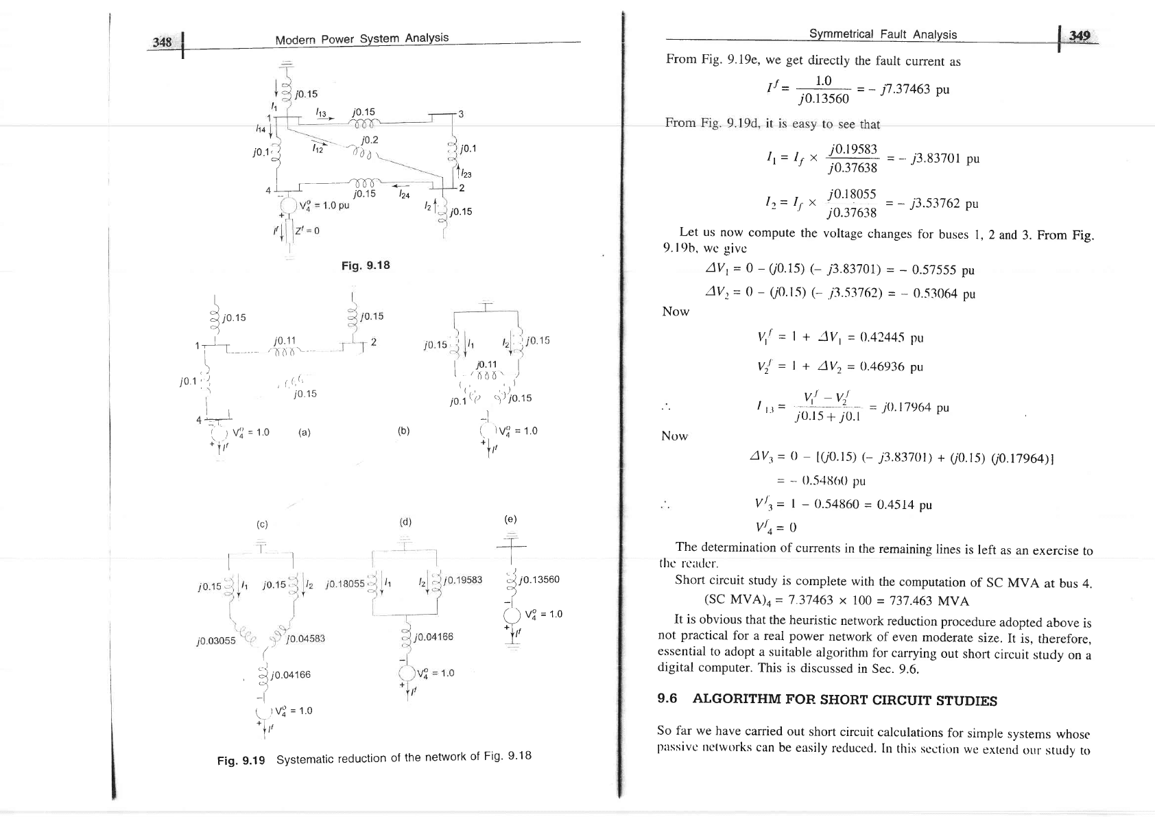
Solution
Changes
in
voltages
and
currents
caused
by
a
short
circuit
can
be
calculated
from
the
circuit
model
of
Fig.
9.18.
Fault
current
1/
is
calculated
by
systematic
network
reduction
as
in
Fig.
9.19,
I
Z
50
Reactor
C
reactance
=
0.12
x 50
=
0.2
pu
=
0.15
pu
-
0.24
pu
(0.069
+i0.138)
(a)
j0.2
j0.12
jo.24
Tie
bar
1
yo
=
1Z0o(
Fig.
9.16
(b)
lo*
!o;E
,^o I Moclern Power Svstem
AnalYsis
I
14
tt
=
-*=
=
-
jt.37463
pu
j0.13s60
t,=
rs x
i:
i3;::
=
-
j3
837or
pu
j0.37638
12=
r, x
{:
i::::
=
-
j3.53
762 pu
-
''
j0.37638
Let us
now
compute
the
voltage
changes
fclr
buses
l,2and
3. From Fig.
9.
l9b,
wc givc
AVr-
0
-
(/0.15)
(-
j3.8370r)
=
-
0.57555 pu
AV,
=
0
-
(iO.l.s) (-
.i3.53762)
=
-
0.53064
pu
Now
jo
1,
),
7
D':
_
jo.2
[0
t,
i0.1
A,
l,zs
2
t,
i,
-t,
10.15
I
I r
-
---rnTl
4+
ib.rs
Izt
\
i
ro'rs
o)
r
-f-
i.0.11
I
t--
-
'AtiA'-
l,
i0
1'':,
,
,t,.(^
.-
t
iots
ll
4T
(
tvl=to
(a)
*
irt
(c)
l''l
I
F'tt
I
I
2iI06'
)
(rlr
io.t\P
''r),}o'rs
-l
(b)
(.
)vl
=
t.o
ir
fr'
(
,-l
,
-J
10.04166
tt*)
-i
(
)V?
=
1.0
\..
t.
Ill
I
(e)
+
I
,-j
;0.
''
uuuo
l
(
)
v?
=
t.o
Tr
V,'=
l+
lVt=0.4244.5
pu
V),
=l+
AVz=0.46936pu
.
v,J
-vJ
/
l-t
=
,of
tr.o.t
=
J0'17964
pu
AVy=
0
-
[(/0.15)
(-
j3.83701)
+
Q0.15)
(/0.17964)l
=
-
0.54fi(r0
pu
Vtt=
I
-
0.54860
=
0.4514 pu
vlo=
o
The
determination
of
currents
in the
remaining
lines
is left
as an
exercise
to
tltcr
rr'ldcr.
Short circuit
study
is complete
with
the
computation
of
SC
MVA
at bus
4.
(SC
MVA)^
=
7 .37463
x
100
=
737.463
MVA
It is
obvious that
the
heuristic
network
reduction
procedure
adopted
above
is
not practical
for
a real
power
network
of even
moderate
size.
It is,
therefore,
essential
to
adopt
a suitable
algorithm
fbr
carrying
out
short
circuit
study
on
a
digital
computer.
This is
discussed
in
Sec.
9.6.
9.6 ALGORITHM
FOR
SHORT
CIRCUIT
STUDIES
So far
we have
carried
out
short
circuit
calculations
for
simple
systems
whose
llitssivc
ttctworks
can
be
easily
reduced.
In this scction
wc
extcnd
our study
to
Now
Fig.
9.19
Systentatic
reduction
of
the
network
of
Fig'
9'18
i*.3€0
-l
Modern Power
System
Analysis
large
,tyrt"-r. In orcler to apply the four steps of short
circuit computation
developed earlier
to
large
systems, it is necessary to evolve a systematic
general
algorithm so that a digital computer
can
be used.
Gen 2
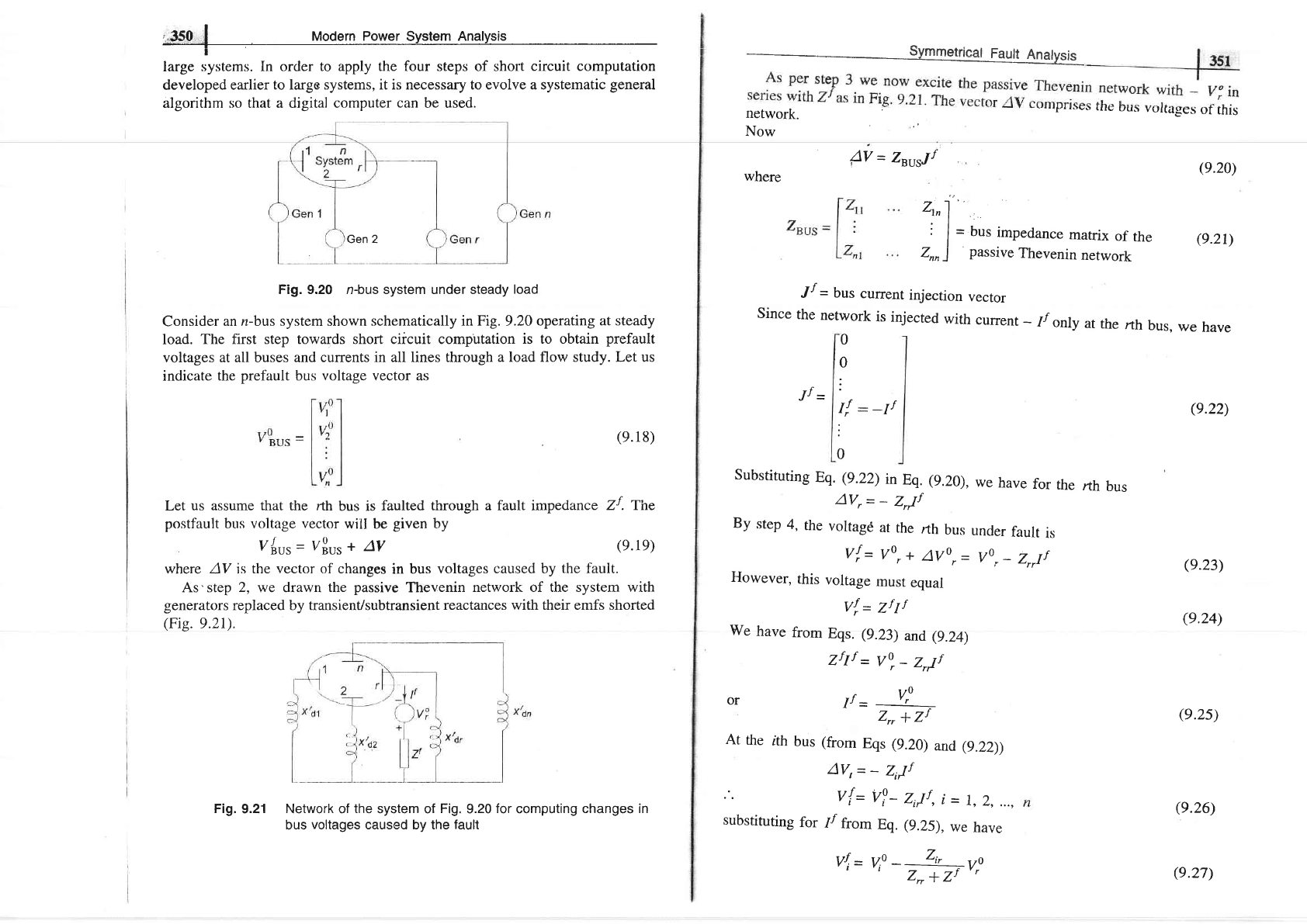
Fig. 9.20 n-bus system under steady
load
Consider
an n-bus system shown
schematically in Fig.9.20 operating
at steady
load.
The first step towards short ciicuit computation
is to obtain
prefault
voltages at all buses and
currents in all lines through
a load flow study. Let us
indicate
the
prefault
bus voltage vector as
_
Symmetr.ic-,.....,*",,;al
Fault Anatlrsis
4V
=
Z"urJf
where
.7
-'l
'-
otn
I
i
I
=
bus
impedance
matrix
of
the
e.2D
Znn
)
passive
Thevenin
network
rth
bus
(e.20)
(e.22)
(e.23)
(e.24)
u//
=
bus
current
injection
vector
Since
the
network
is
injected
with
current
-
1/
only
at
the
rth
bus,
we
have
0
0
Let
us assume that the rth
bus is
faulted
through a fault impedance
Zf . The
postfault bus voltage vector
will be
given
by
V{ur=
VBus
+
AV
:
rf ,f
I,
:
-I'
:
Substituting
Eq. (9.22)
in
Eq.
(g.20),
we
have
for
rhe
AV,
=
-
ZrJf
By
step
4,
the
voltage
at
the
nh
bus
under
fault
is
v!=
vor+
avo,-
vor-
Z,Jf
However,
this
voltage
must
equal
Vd
=
7f
1f
We
have
from
Eqs. (9.23)
and (g.24)
zftf
-
vo,_
z,Jf
or
f=
V:
Zr,
+
Zf
At
the
rth
bus (from
Eqs (9.20)
and (g.22))
AV,
=
-
Z,Jf
v{=
v?-
Z,Jf,
i
=
1,2,
...,
substituting
for
//
from
Eq. (9.25).
we
have
vI=
vf
-
:
zl';rv!
z*+L
/-
(e.18)
(e.1e)
where AV is
the vector of changes
in
bus
voltages caused by
the fault.
As'step
2,
we drawn
the
passive
Thevenin
network of the system with
generators
replaced by transient/subtransient
reactances with their emfs shorted
(Fie.9.21).
Fig.
9.21 Network of
the
system of
Fig.
9.20
for
computing
changes in
bus
voltages
caused by the
fault
(e.2s)
(e.26)
(e.27)
network.
_--.rr.vv\,
rrrv
u(rr
vurraegcs
oI
mls
Now
Fi1.9.22
f",
=
&#;
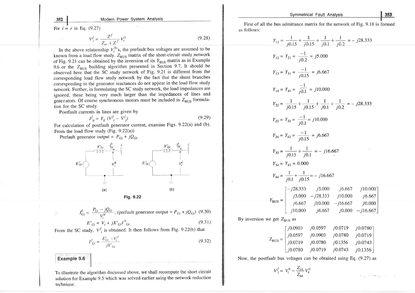
(prefault generator output
=
Pci
+
iQci)
(9.30)
v,u
E'Gi
=
V,
+
jXt"/t)",
(9'31)
From
the SC
study,
Vf
,is
obtained.
It then
follows
from
Fig.
9.22(b)
that
I rca
Siimmetrica!
Fault
,Analysis
|
-?53
First of all the bus
admittance
matrix
for the network
of
Fig.
9.18
is
formed
as follows:
-r
-
-
j28.333
352
i
rtllodern
Power
System
Analysis
Fori=rinEq.(9.27)
(e.28)
In the
above
relationship
V,o'r,
the
prefault
bus
voltages
are assumed
to be
known
from
a load
flow
study.
Zuu,
matix of
the short-circuit
study
network
of
Fig. 9.21
can
be
obtained
by
the
inversion
of
its furr5
matrix
as
in Example
9.6
or the
Zru, building
algorithm
presented
in Section
9.7.It
should
be
observed
here that
the
SC study
network
of
Fig. 9.2I
is different
from
the
corresponding
load
flow study
network
by the
fact'that
the shunt
branches
corresponding
to
the
generator reactances
do
not appear
in
the load
flow
study
network.
Further,
in
formulating
the
SC study
network,
the
load
impedances
are
ignored,
these being
very
much
larger
than
the
impedances
of
lines
and
ginerators. Of
course
synchronous
motors
must
be included
in
Zuur
tormula-
tion
for
the SC
study.
Postfault
currents
in
lines
are
given by
f
u=
yu
(vri-
vt)
Q.29)
For
calculation
of
postfault
generator current,
examine
Figs.
9.22(a)
and
(b).
From
the
load flow
study
(Fie.
9.22(a))
Prefault
generator output
=
PGr
+
iQci
-l
Yr.>=Yrt=
_-
175.000
tL Lt
j0.2
-l
Y3=
Yy
=
;r*
-
i6.667
-1
Yrq=
Yq=
J,3.l
=
i10.000
Yzz=
.:-++-+++:^
=-
j28.333
j0.15 j0.1s
"
jj.r j0.2
Yzt=
Yn=
+=
j10.000
j0.1
-l
Yzq=
Yn=
F;
-
i6.667
Y-.=
I
+
I
=-i16.667
'33-
j0.15
'
jo.1
Ytq= Yqt
=
0.000
v
-
I
-
I
Yqq=
,-
*
,.""
--
i76'667
I1
-t-
I
I
--r
(b)
(a)
By inversion
we
get
Z",tt as
rrc,=tfr!
i
ir;rnr;;.;
I
(e.32)
j0.0s97
j0.0903
j0.0780
jo.o719
j0.0719
j0.0780
j0.13s6
j0.0743
Now, the
postfault
bus
voltages can be obtained using Eq.
(9.27)
as
To
illustrate
the
algorithm
discussed
above,
we shall
recompute
the
short
circuit
solution
for Example
9.5
which was
solved
earlier
using the
network
reduction
technioue.
V{= Vo
-Zto
VP
rrZooa
,2.tr!A | ^/lndarn Pnrrrar Qrratarn Analrrcic
JJ' I
lYlVVVlll
I
Vltvl
Vtvlvlll
,
rlrsrtvre
I
The
prlfault
condition
being
no load, V0r=
Voz=
V03- Voo=
1pu
- r 1.000
,J
-
_
-
2,,{or
Zzz)
malriaal
| |
tglt
tvql
Eat
qu
1.00
j0.0903
=
-
jIL074I97
pu
r.o-
i99199
x
10
=0.4248pu
i
0.1356
vrz= v:
-
?':
r,',
LLzoor
i
0.0710
=
1.0
-
o -
::
x
1.0
=
0.4698
pu
j0.1356
7
v{= v\
-
1*
vf
Zoo
i0.0743
=
1.0
-
'
-
::
_:
1.0
=
0.4521
pu
j0.r3s6
vi
=
o'o
Using Eq.
(9.25)
we can obtain
the
fault current
as
7r=
.r-^0.9^o=-
=,
j7.3j463pu
j0.13s6
These
values
agree
with those
obtained
earlier in
Example 9.5.
Let us
also
calculate
the
short circuit
current
in lines 1-3,
1-2,
l-4,2-4
and
2-3.
,r
v,r
-v{
0.4248-0.4521
[12=
-:-
-
jo'182
Pu
z.n
i0.15
- r
v,r
-v{
0.4248-
0.4698
trrz=
-'_-
'2-:-
_
j0.225
pu
zrz
.i0.2
r r
yr -v{
_
o.4z4v-o
,
t4
-
-
i4.248
pu
4q
jo'l
. r
u'l
-
v{
0.46e8
-
o
Iiq='-
q
---=
-
j3.132pu
zz+
i0'15
--r
v{
-v^
0.4698
-0.4521
I-Izt=
tiutt
=
TO-
=
-
./0.177 Pu
For the
example on
hand this method
may appear
more involved
compared
to the heuristic
network
reduction
method
employed
in
Example
9.5.
This,
however, is
a systematic
method and
can be
easily adopted
on
the digital
computer
for
practical
networks
of large size.
Further,
another
important
feature
of the method
is that having
computed Zu's,
we can
at once
obtain
all the
required short
circuit
data for a fault on
any bus. For
example,
in
this
particular
system, the
fault
current
for a fault on
bus
I
(or
bus
2)
will be
By Inventing
Y"u"
/nus
=
Yrus Vsus
or
Vsus
=
[Y"ur]-t
/eus
=
Znus /eus
or
Zsvs
=
[Yuur]-t
The
sparsity
of fsu,
may
be retained by
using an efficient inversion
technique
[1]
and
nodal
impedance
matrix can
then be calculated directly
from
the
factorized
admittance
matrix.
This is beyond
the scope of this book.
Current
Iniection
Technique
Equation
(9.33)
can
be
written in the
expanded form
V1
:
211\
*
Ztzlz
1
...
*
ZnIn
v2:22111
+
22212
+... +
zznln
(e.34)
(e.33)
(e.35)
V,
:
Zntll
*
2,,21r
*
.. .+ Z,,nl,,
It
immediately
follows
from
Eq.
(9.34)
that
z
-v'l
"ii
-
Irl,r:
rz
:...:
rn=o
I1-r0
Also
Zi,
-
Ziii
(Znvs
is
a symmetrical
matrix).
As
per
Eq.
(9.35)
if a
unit current
is injected at bus
(node)
7,
while the
other
buses
ere kept
opon
circuited,
the bus
voltages
yield
the
values
of
theTth
column
of
Zuur.
However,
no
organized
computerizable
techniques are
possible
for
finding
the
bus
voltages.
The
technique
had
utility
in AC
Network Analyzers
'where
the bus
voltages
could
be read by
a voltmeter.
Consider
the network
of
Fig. 9.23(a)
with three buses
one of which is a
reference.
Evaluate
Zsus.
Sotution
Inject
a
unit
current
at
bus
I keeping bus
2 open circuit, i.e.,
Ir
=
I.
and
Ir=
0
as in
Fig. 9.22(b).
Calculating
voltages at buses I
and 2,
wehave
Ztt=Vt=7
Zzt=Vz=4
.f
356
|
Modern
Power
System Analysis
Now let It
=
0
and
12
=
1. It similarly
fbllows
that
Ztz=Vt=4=
Zn
Because
of the above
computational procedure,
the Zru,
matrix
is
referred
to as the
'open-circuit
impedance
matrix'.
Z"vs
Building
Algo4ithm
It
is
a step-by-step programmable
technique
which
proceeds
branch
by branch.
It has
the advantage
that any
modification
of the
network
does not require
complcte
rebuilding
of Z"ur.
Consider that Zrur
has been
formulated
upto
a certain stage
and another
branch is
now added. Then
Zrur
(old)
Zo:branch
impedance
Zsus
(new)
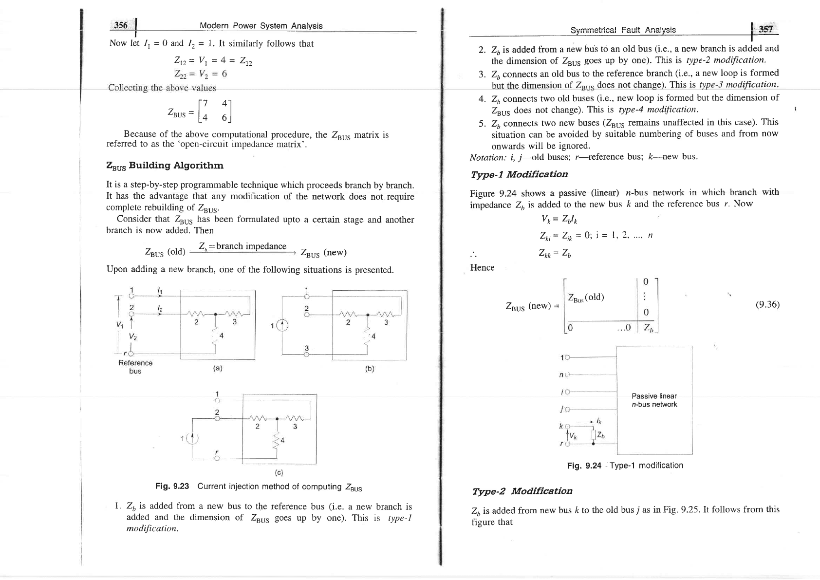
Upon adding a new
branch,
one of the
following
situations is
presented.
Fig. 9.23 Current injection
method of
computing Zru.
26 is
added from a new
bus to
the reference
bus
(i.e.
a new branch is
added
and
the
dimension
of
Zry5
goes
up
by one). This is type-I
modificution.
Symmetrical
Fault
Analysis
!,
f5l
,
4r,
the dimension
of Zsu5
goes up by one).
This is
type-2 modification.
3.
Zuconnects
an old
bus
to the
reference branch
(i.e.,
a new loop is
formed
dimension
of 2o,,"
does not change).
This is
type-3 modification.
4. Zuconnects
two
old buses
(i.e.,
new loop
is
formed
but the dimension
of
Zuu, does
not change).
This
rs type-4
rnodittcation.
5.
Zu connects
two
new buses
(Zeus
remains
unaffected
in this
case).
This
situation
can
be avoided
by suitable
numbering of
buses
and from
now
onwards
will be
ignored.
Notation:
i,
j-old
buses;
r-lsfelence
bus; k-new
bus.
Type-
1
Modification
Figure
9.24
shows
a
passive
(linear)
n-bus
network
in
which branch
with
impedance
2,,
is added
to the
new bus
k
and
the
reference
bus r. Now
Hence
V*=
ZJ*
Zri=
Z*
=
0;
i
=
1,2.
....
tt
Zm=
Zu
Fig. 9.24
,
Type-1 modification
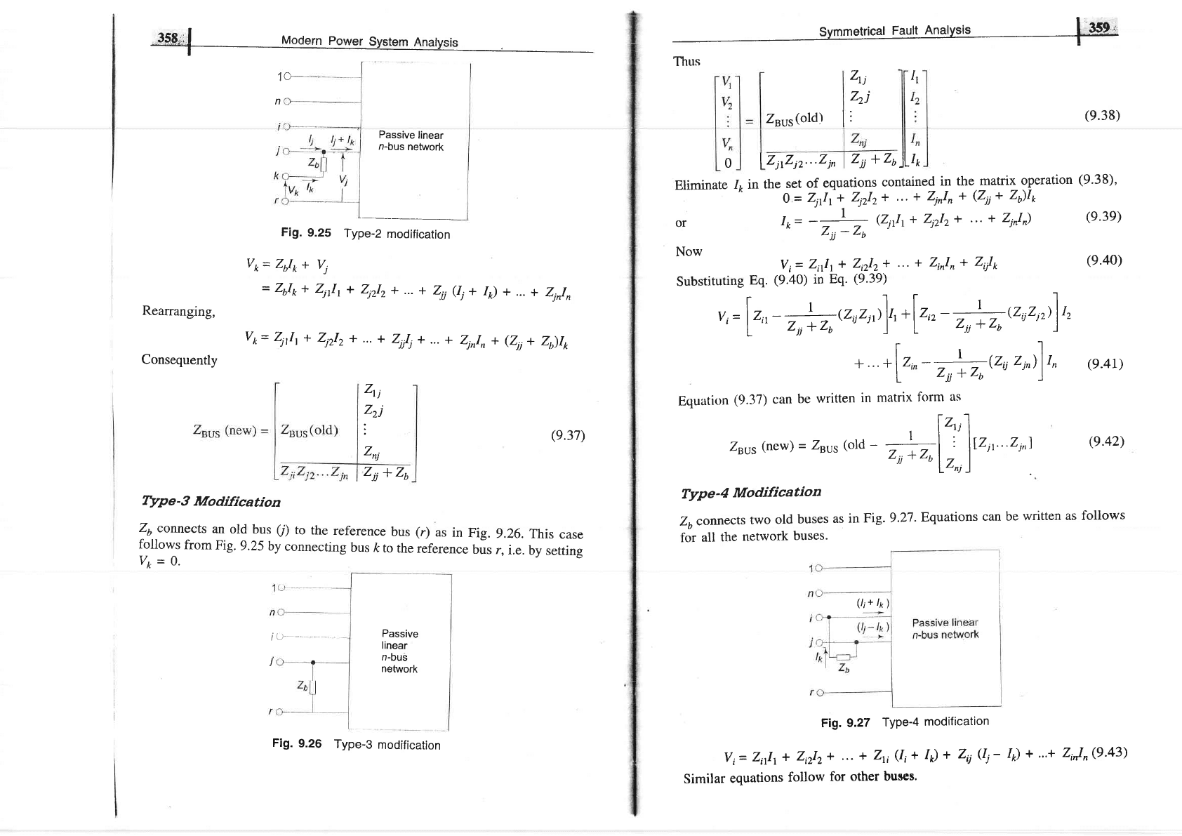
Type-2
Modification
Zo is
added
from
new
bus ft to
the old
bus
7
as in Fig. 9.25.It
follows from
this
figure
that
l7
41
Zvus=
l+
6l
s,,"
(old)
Zsvs
(new)
-
(e.36)
t.
Passive
linear
n-bus
network
35S;,1 MorJern Powcr Srrctarn anatrroio
1O_
n
Passive
linear
n-bus
network
Fig.
9.25
Type-Z
modification
Vo=
Zdo
+
V,
=
Zr,I*+
ZiJr+
Zlzlz
+...
+
Zii
ei*
I)
+
...
+
Zinln
Rearranging,
V*=4lt+
Zlzlz
+...
+
2,,1,+...+
Zi,ln+(Zii+
Z)lk
Consequently
Zrj
zzj
Zsvs(old)
I
:
(e.38)
o
I lzyziz...zi,
I
zii
+
z,
)lI*
lr
Eriminate
{
in
the
3":';,,iiy';;;?::"i"t
i.I"
a;y>;i:ation
(e'
3
I
)'
1
or
'o=
-12
(\1Ir+
Zi2Iz+
"'
+ ZlnI)
(9'39)
Now
V;=
2;111+
Z,rI,
+
"'
+ Z'nIn
+
Z;/r
(e.40)
(e.42)
Zti
Zzj
:
Znj
(e.37)
Substituting
Eq.
(9.40) in
Eq.
(9.39)
,,
=
lr^
-
h(z*
1
rr]a
*
lr,,
-
"h
rz
uz,,>)r,
+
+
lr^-
^i{zu
2,,1)r,
(s.4t)
Equation
(9.37) can
be
written
in matrix
form
as
. |t"f
ZsLr5
(new)
=
znvs(old
-
;+;l
:
ltz't"Zv)
"jjT"ulz,,
l
zjj
+
zb
IYpe-3
Modification
zu
connects
an
old
bus
(l)
to
the
reference
bus
(r)
as
in
Fig.
9.26.
This
case
follows
from
Fig.9.25
by
connecting
bus
ft
to
the
reference
bus
r,
i.e.
by
setting
v*=o'
Type-
Modification
zo
connects
two
old
buses
as
in
Fig. 9.27
. Equations
can
be
written
as follows
for
all
the
network
buses.
Fig. 9.27
TYPe-4
modification
Vi=
Z;11,
+
Z,lr+
"'
+
Zri
(Ii
+ /)
+
ZU
Qi-
Similar
equations
follow
for
other
buses.
J
Passive
linear
n-buS
network
(l;+ lp
Fig.
9.26
Type-3
modification
/o)
+ ...+
ZiJ"(9.43)
360
|
Modern
power
System
Analysis
I he voltages
of the
buses
i and
j
are,
however,
constrained
by
the
equation
(Fig.
9.27)
Symmetrical
Fault
Analysis
I
fOt
Step
I: Add
branch
2,,
-
0.25
(from
bus
I
(new)
to
bus
r)
Step
ZBUS
=
t}.25l
(i)
Add
branch
Zzt
=
0.1
(from
bus
2
(new)
to bus
I
(old));
type-Z
V,=
Z,rlo+
Vi
or 21111
+
\212+
...
+
Zit
(1,+
I)*
Zii
(Ii-
I) + ...
+
(e.44)
zi,In
=
Ztl*+
Z,rl,
+
Z,rl"
+
...
+
ZlU,+
I
earTangtng
_I
0
=(Zit-
21)
Ir+ ...
+
(Zti-
Z)
Ii+
eu-
Z)
Ii
+...+
(Z*
-
21,)
In +
(Zu
*
Zii *
Zii
-
Zi
-
Z)
11,
e.45)
Collecting
equations
similar
to
Eq.
(9.43)
and
Eq.
(9.45)
we
can
write
vl
V
vn
0
(9.46)
Eliminating
1o
in
Eq.
(9.46)
on lines
similar
to whar
was
done
modification,
it follows
that
l'"
lZ,,
with
the
use of
fbur
relarionships
Eqs
(9.36),
(9.37),
(9.42)
and
(9.47)
bus
impedance
matrix
can
be
built
by a
step-by-step
procedure
(bringing
in
one
branch
at
a tinle)
as illtrstratc'tl
in lixrrrnple
9.8.
This
pror.cdrrr-c
-hcing
a
mechanical
one
can
be
easily
computerized.
When
the
network
undergoes
changes,
the
modiflcation
proceclures
can
be
cttrployccl
to rcvisc
thc
bLrs
irtrpcdance
rnatrix
ul'thc
nctwol'k.
Thc
opeling
o1
a
line
(Ztt)
is equivalent
to
adding
a branch
in
parallel
to it
with
impedance
-
2,,
(see
Example
9.8).
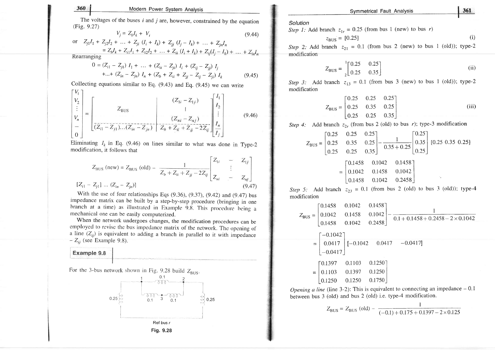
j Example
9.8
For
the
3-bus
network
I
I
I
!,--
0.25
l,'
(--
I
l
I
Ref bus
r
Fig.
9.28
zsvs=',lZ:11,
31i]
(ii)
Step
3: Add
branch
,rt
=
0.1
(from
bus 3
(new)
to bus I
(old));
type-Z
modification
lo.2s
o.zs
0.2s1
zsvs
=
|
o.zs
o.3s
o.2s
|
(iii)
lo.2s
0.2s
0.3s..l
Step
4: Add
branch
zz,
(from
bus
2
(old)
to
bus
r); type-3
modification
10.2s
o.zs
0.25'l
[0.25-l
Zet)s
=
|
o.zs
0.3s
0.2s
| |
o.ts
I to.zs
0.3s
0.251
Lo.2s
o.2s
o3sl
o'3s
+
o
"
Ln.trj
[0.14s8
0.1042
0.14s8-l
=
I
o.ro+z
o.r4s8
o.lo42
|
fo.tott
o.ro42
o.24s8l
Step
5:
Acld
branch
iz-r
=
0.1
(from
bus
2
(olct)
to brrs 31old)):
type-4
modification
[o.l4s8
0.1042
0.l4s8l
zsvs
=
l
o.'oo,
0.1458
o.to42l-
|
0.1
+
0.1458
+
0.2458-2xO.lO42
10.l4s8
O.tO42
0.24s8
)
[-0
1042.l
=
I
0.0417
|
[-o.to+z
0.0411
-0.0417]
[-o.o+tz-l
lo.r3e7
0.1103
0.12501
=
|
0.1ro3
o.I3e7
0.1250
I
|
0.1250
0.1250
0.17sol
Oltenirtg
o
tinu
(line
3-2):
This is
equivalent
to connecting
an intpeclance
-
0.I
between
bus 3
(old)
and
bus
2
(old)
i.e.
type-4
modification.
Zsus=
Zuur(olcl)
-
(-01)+ol?5
#
Z131,s
(new) =
Zsuts
(old)
-
lzit
-
z1t)
...
(zi,
-
zi))
zb+zii*Zii-zzij
Zsus
I
i,J
o r.
I
shown
in
Fig.
9.28
build
r
9l z
I
'irl
l
L-,
tr
ili
-,
--
6"11-.
I
0.1
3
o.t
filf.lid,
Modern Power
System
Anatysis
-r-r-^r r^..tr Ana*raio
ffir
:)ymmelrlual
raull
rurqryo's
r**
Now
I
-
|
0.1042
0.14s8
0.1042l;
(same
as in
step
4)
0.1458
0.1042
0.2458
|
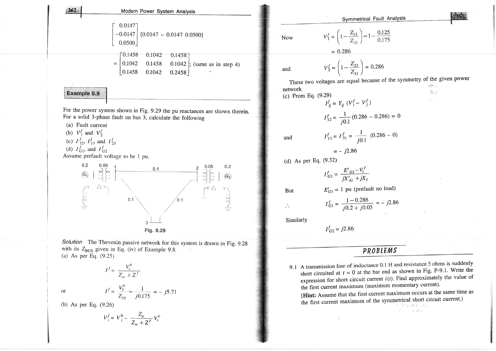
For
the
power
system
shown
in
Fig.
9.29 the pu
reactances
are
shown
therein.
For
a
solid
3-phase
fault
on bus
3,
calculate
the
following
(a)
Fault
current
(b)
V\ and
vt
(c)
It,r,
I'\,
uxl
Il,
(d)
1fr,
and If,
Assume
prefault
voltage
to be I pu.
0.2
0-.09
1
and
il=(FZE-)=0.286'i2-[^
zu)
These
two
voltages
are
equal
because
of
the
symmetry
of
the
given
power
network
(c)
From
Eq.
(9.29)
and
But
|ffr
Jt
-
or
1f
-
(b)
As
per
Eq.
(9.26)
rr.f
-
v
i-
\,
//
o
''
\
,/'0.,
\/
\..
,/
.,
ll
3'
'
Fig.
9.29
[
0.0147-l
tl
|
-0.0147
|
10.0147
-
0.0147
0.0s001
L
o.osoo_J
(d)
Iri
=
Y,j
(vl
-
vl)
Irtz=
+(0.286
-
0.286;
=
g
j0.1
'
I\t=t|t=
fr
ro.186-o)
-
-
i2.86
As
per Eq.
(9.32)
, r
E'
or-vrf
r
Gr
-
ixtic
+
ixr
E'Gr
=
1
Pu
(Prefault
no
load)
JI-
F
0.1
c)
|
i-,,
IL.=
1-0'286--
=-
j2'86
Gt-
io.2+io.os
SimilarlY
Ifcz=
i2.86
Solution
The
Thevenin
passive
network
for
this
system
is
drawn
in
Fig.
9.28
with
its
Zru, given
in Eq.
(iv)
of
Example
9.8.
(a)
As
per
Eq.
(9.25)
PROB
LE
M
S
A
transmission
line
of
inductance
0.1
H
ancl
resistance
5 ohms
is
suddenly
short
circuited
at
t
=0
at
the
bar
end
as
shown
in
Fig'
P-9'1'
Write
the
expression
for
short
circuit
current
i(r).
Find
approximately
the
value
of
the
first
current
maximum
(maximum
momentary
current)'
[Hint:
Assume
that
the
first
current
ntaximum
occurs
at the
same
time as
the
first
current
maximum
of
the
symmgtricl.:non
ttrcuit
current')
V:
2,,
+
Zl
Yo-:._1--
--
js.jl
zn
j0.175
vl
-
--Zt--yu
'
zrr+zl'r
9.1