Kothari D.P., Nagrath I.J. Modern Power Systems Analysis
Подождите немного. Документ загружается.

fl6 -l
Modern
Po
I
To illustrate
the
simplification
of the state
estimation
algorithm,
consider
the
linearised
measurement
equation
for
the injections
only case.
Since the
system
is
partitioned into
three
subsystems,
this equation
may
be written
as
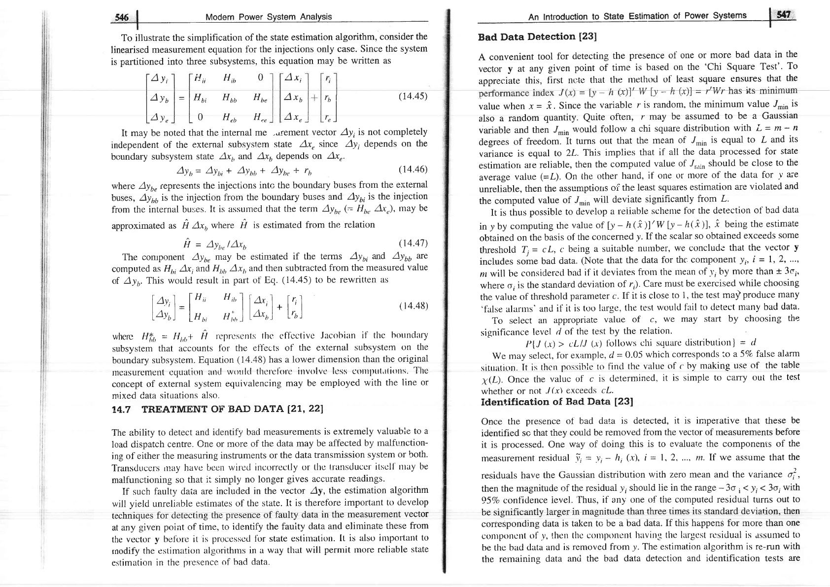
Ayi
H,,
H,, o
A*,
A*,
A*,
It
may be
noted that
the internal
me ..rrerrrert
vector Ayt
is not completely
inclepenclent
of the
external
subsystem
state
Axu
since Ay,
depends on
the
boundary
subsystetn
state Axr,
and
Ax6 depends
on Axr.
An
lntroduction
to state
Estimation
of
Power
systems
I
t{7
Bad
Data
Detection
[231
A convenient
tool
fcr
detecting
the
presence of one
or more
bad
data
in
the
vector
y
at
any
given
point
of
time
is based
on
the'Chi
Square
Test'.
To
appreciate
this,
flrst
nc:te
that
the
trrethod
t-ll least
square
ensures
that
the
rflLW
Ta
:
1r
(t)l-
/ltgr
haritrminimum
value when
x
-
i.
Since
the
variable
r is random,
the
minimum
value ,I.in
is
also
a
random
quantity.
Quite
often,
r may
be assumed
to be
a Gaussian
variable
and
then
.I*1n
would follow
a
chi square
distribution
with
L
=
m
-
n
degrees
of
freedom.
It turns
out
that
the
mean
of ./,o1n
is equal
to
L
and
its
variance
is equal
to
2L.
This
implies
that
if
all the
data
processed for
state
estimatiorr
are
reliable,
then
the
computed
value
of ../r,r,n
should
be
close
to
the
average
value
(=L).
On
the
other
hand,
if one
or
ntore of
the
data
for
)'
tre
unreliable,
then
the
assumptiorrs
of the
least
squares
estimation
are
violated
and
the
computed
value of
J*1n
will
deviate
significantly
from
I.
It
is
thus
possible
to
develop
a reiiable
schetrre
for
the detection
of
bad
data
in
y
by
computing
the
value
of
[y
-
h(i)l'w
ly
-
h(r)],
i
being
the
estimate
obtained
on
the basis
of
the concerned
y.
If
the
scalar
so obtained
exceeds
some
threshold
Ti
-
c L,
c:
being
a suitable
nuutber,
we conclude
that
the vector
y
includes
some
bad
data.
(Note
that
the
data
for
the. cornponent
y;,
i
-
1,2,
...,
nr will
be
consiclerecl
bacl
if it deviates
from
the
tnean
of
r',
by
more than
t
3e,.
where
o,
is the
standard
deviation
of
r;). Care
must
be exercised
while
choosing
the
value
of
threshold
parameter
c.If
it
is
close
to 1,
the test
maf
produce many
'talse
alal1s'
ancl
il it
is tt-rt-r
large,
the
test
worrld fail
to detect
nlany bad
data.
To
select
an
appropriate
value
of c,
we may start
by
choosing
the
significance
level
d
of the test
by
the relation'
I'lJ
(x)
> cLlJ
(.r)
lbllows
chi
squale
distribution)
=
6/
We
rnay
select,
fbr
example,
d
=
0.05
which
corresponds
to
a 5Vo false
alarm
sitrrltign.
[t is thcn
possible to
find
the
valr.re
of c hy making
use
of
the
table
X@).Once
the
valuc of
c
is
determined,
it
is
simple
to cary
out the
test
whether
or
not
.l(x\
exceeds
cL.
Identification
of
Bad
Data
[231
Once
the
presence of bad
data
is detected,
it is iraperative that
these
be
identified
so that
they
could be
removed
from the
vector
of measurements
before
it is
processed. One
way
of
doing
this is to
evaluate the components of
the
measurement
residual
!,
=
y,
-
h,
(.x\,
i
=
1,2,..., m. If
we assLlme
that
the
residuals
have
the
Gaussian
distribution
with zero
mean and the
varLance
4,
then
the magnitucie
of
the resiciuai
y,
shouici
iie in the range
-
3o
i
(
)i
(
3or
with
95Vo
confidence
ievel.
Ihus,
if any one of
tlte cotnputed residual
turns out
to
be significantly
larger
in magnitude
than three
times its standard devia,tion,
then
corresponding
data
is
taken to be
a bad
data. If this happenS for more
than
one
con)potrctr(
ol'_y,
thcn thc
con'lponcnt
lurvingl thc largcst
rcsidual is
assunted
to
be
thc bad
data
and
is removed
from
y.
The
estimation
algorithm
is
re-run
with
the
remaining
data
and the bad
data detection
and identification
tests
are
Ayr,
ay"
Hu,
Huu Ho,
0
Hra
H""
,ol
,"]
(r4.4s)
(r4.46)
(14.47)
(
r4.48)
Ayr=
Ayt,i + Aynr,+
Ayu,
+ ru
where Ayo"
represents
the injections
intc
the boundary
buses
from
the external
buses,
Ay66is
the
injection from
the boundary
buses
znd
Ay6,
is
the
injection
fiom
the
internal buses.
It is assurned
that
the term
Ayu,
(=
Ht,, Axr),
may
be
approximated
as
n A*, where
A
It estimated
from the
relation
H
=
Ayt,nlAxl,
The
conrponent
Ayu" may
be estimated
if the terms
Ayy,
and
Ayuo
ne
computed
as
H,,, Ax,and
H1,1,
Ax1, and
then subtracted
from the
measured
value
of
Ayo. This
woulc! result
in
part of Eq.
(14.45)
to be rewritten
as
l^;,)=l',;;,
',;:;)l*,1
.
[;]
whcrc Ht,,
=
H
t,t,t
U
pcrprcscrnts
fhc cff-ccf
ivc Jacohiltn
if the
hottnclitry
subsystern
that accounts
for
the
eff'ects of
the external
subsystern
on
the
boundary
subsystem.
Equation
(14.48)
has a lower
dimension
than the
original
tncasurclncrtt
cclLrltion
und
worrlrl
tltcrclorc
irtvolvcr
lcss ctltttlltr(.tliolls.
Tltc
concept of
external
system
equivalencing
may
be employed
with the
line or
rnixed
Cata
situations
also.
14.7
TREATMENT
Ol.- BAD
DATA
127,221
The
ability
to
detect
and identify
bad measurements
is extremely
valuable
to a
load dispatch
centre.
One or
more of
the data
may be
affected
by
rnalfunction-
ing
of either
the
measuring
instruments
or
the data
transmission
system
or both.
Transtlucers
rnay have
becn
wilcd
incorrcctly
or
tlto l.rattsduccr
itscll
rttay be
malfunctioning
so
that
it
simply
no longer
gives accurate
readings.
If such
faulty
daia are
included
in the
vector Ay, the
estimation
algorithm
will yielcl unreliable
estimates of
the state.
It
is therefbre
important
to develop
techniques
for detecting
the
presence of
faulty
data
in the measurement
vector
at
any
given point of
time, to
identify the
fauity
data
and eliminate
these
from
the
vector
y
befble
it is
processcd lbr state
estinration.
[t is
alstl ilttpoltant
to
rnodify
the
estirnation
algorithms
in a
way
that will
permit tnore
reliable
state
estimation
in the
p!esence of
bad data.
,548
,!
Modern
power
System
Analysis
I
performed
again
to
find
out if
there
are additional
bad data
in
the measurement
set.
As
we
will
see
later
bad
rneasurement
clata
are detected,
eliminated
and
replaced
by
pseudo
or calculated
values.
of Bad
Data
The procedures
described
so far
in
this
section
are quite
tedious
and
time
consuming
and rnay
not
be utilized
to
remove
all the
bad
data
which
may
be
present
in
the vector
y
at a
given
point
of time.
It
may
often
be desirable
on
the
other
hand
to
modify
the
estimation
algorithms
in
a
way that
will
minimise
the
influence
of the
bad
data
on the
estimates
of
the
state vector.
This
would
be
possible
if
the
estimation
index
J(x) is
chosen
to
be
a non-quadratic
function.
The reason
that
the
LSE
algorithm
does
not perform
very
well
in
the
presence
of
bad
data
is
the fact
that
because
of the quadratic
nature
of
J(x),
the
index
assumes
a
large value
for
a data
that
is too
far
removed
from
its
expected
value.
To
avoid
this
overemphasis
on the
effoneous
data
ancl
at the
same
time
to retain
the
analytical
tractability
of the quadratic:
perlbrmance
index,
let
us
choose
/(i)
=
s'
(t)
w
sG)
(14.49a)
where
8(t)
is a
non-linear
function
of
the
residual
!.
There
may
be
several
possible
choices
for
this
f'unction.
A convenient
form
is the
so-called
'quadratic
flat' form.
In
this
case,
the
components
of
the function
g (y)
are
defined
by
the
following
relation.
gi
(j)
=
li,
for
j,lo,
1
a,
=
ai,
ftx'
l,/o,>
u,
where
a, is
a
pre-selected
constant
threshold
level.
Obviously,
the
perform-
ance
indcx
./("r)
may
bc cxpressed
as
m
I(i)
=
Dy,
c;)
;- I
.--
I
and
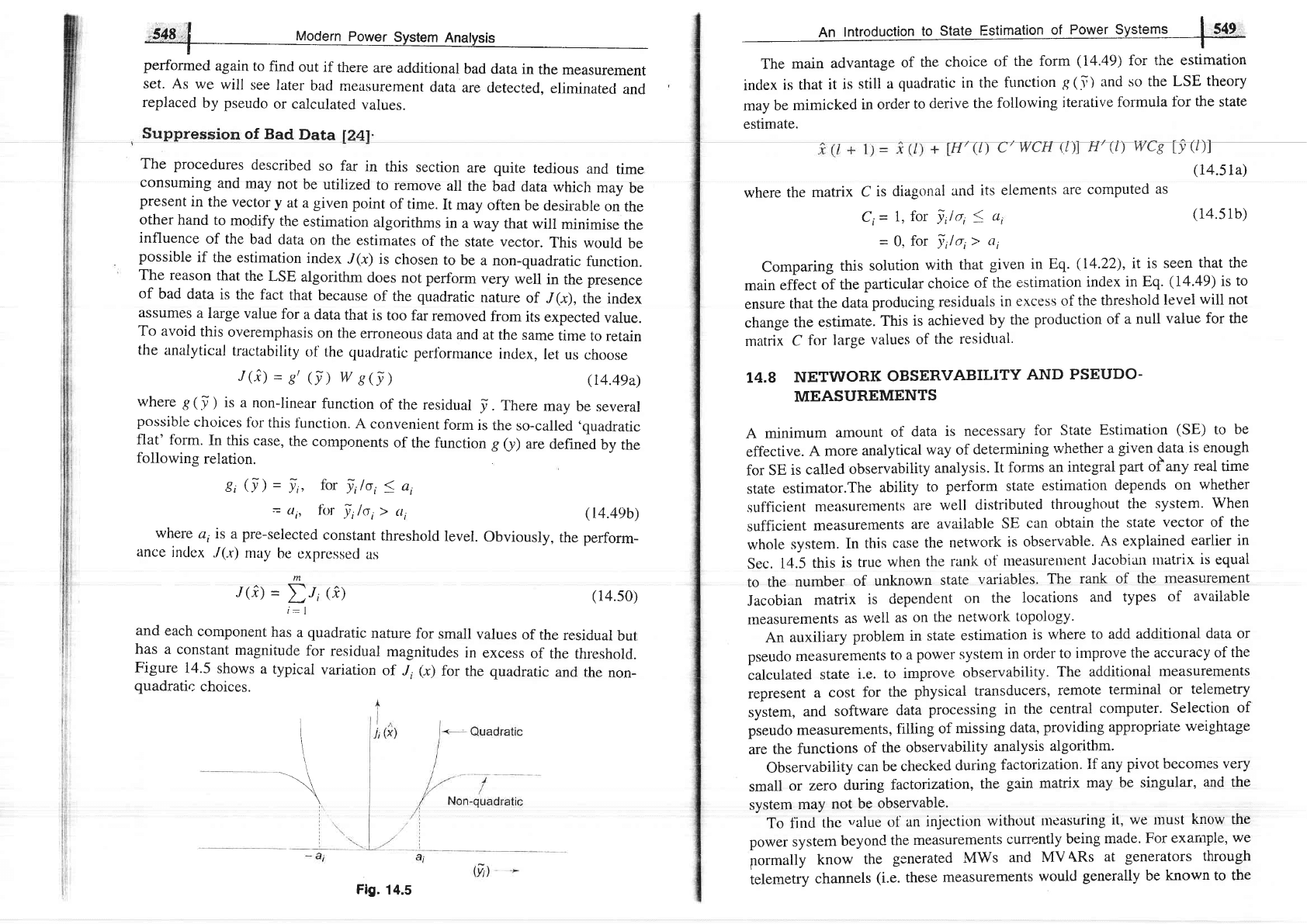
each
component
has
a
quadratic
nature
for
small
values
of the
residual
but
has
a
constant
magnitude
for
residual
magnitudes
in
excess
of
the
threshold.
Figure
14.5
shows
a typicai
variation
of
J,
(.r)
for
the
quadratic
and the
non-
quadratic
choices.
\
(r4.49b)
(14.s0)
An
tntroduction
to
State
Estimation
of
Power Systems
I
549.
t-
The
main
advantage
of
the
choice
of
the form
(14.49)
for
the estimation
index
is that
it
is
still
a
quadratic
in the
function
g(.i)
and so the
LSE
theory
may
be
mimicked
in order
to
derive
the
following
iterative
formuia
for
the state
estimate.
Hr(D
CTWCH
Q)Tfl
(D
WCtfiDI
(74.5ra)
where
the
matrix
C
is diagonal
and
its elements
are computed
as
Ct=
l,
fot
l;lo,
S
ai
=
0,
for
lilo,>
a'
(14.s
1b)
Comparing
this
solution
with
that
given in
Eq.
(14.22),
it is
seen
that the
main
effect
of
the
particular
choice
of
the
estimation
index
in Eq.
(14.49)
is
to
ensure
that
the
data
producing
residuals
in
excess
of the
threshold
level
will
not
change
the
estimate.
This
is achieved
by
the
production
of
a null
value
for
the
matrix
C
for
large
values
of
the
residual.
I4.8
NETWORK
OBSERVABILITY
AND
PSEUDO-
MEASUREMENTS
A
minimum
amount
of
data
is
necessary
for
State
Estimation
(SE)
to
be
effective.
A more
analytical
way of
determining
whether a
given
data
is enough
for
SE
is
called
observability
analysis.
It
forms
an integral
part
olany
real
time
state
estimator.The
ability
to
perform
state
estimation
depends
on
whether
.sufficient
measurements
are
well
distributed
throughout the
system.
When
sufficient
measurements
are
available
SE
can obtain
the state
vector of
the
whole
system.
In
this
case
the network
is observable.
As
explained
earlier in
Sec.
14.5
this
is
true
when
the
rank
of
measurentent
Jacobian
tlratrix
is
equal
to the
number
of
unknown
state
variables.
The
rank of
the
measurement
Jacobian
matrix
is
dependent
on
the
locations
and
types
of
available
rneasurements
as
well
as
on
the
network
topology.
An
auxiliary
problem
in
state
estimation
is where
to
add additional
data or
pseudo
measurements
to a
power
system
in
order
to improve
the accuracy
of
the
calculated
state
i.e.
to
improve
observability.
The additional
measurements
represent
a
cost
for
the
physicat
transducers,
remote
terminal
or
telemetry
sy.stem,
and
software
data
processing
in
the
central
computer.
Selection
of
pseudo
measurements,
filling
of
missing
data,
providing
appropriate
weightage
are
the
functions
of the
observability
analysis
algorithm.
I I - -r-- I l---:- ^ C^^t^-i-^+l^- Tf ^-.' ^i"^+ L^^^-^. .'^-.'
UbsefvaDlllty
Can
De CIICCKCU
UUtrrlB
lilulullzittLltrll.
Il
4IrJ
Prv\rr
r.rvtrrr.rrrlr YvrJ
small
or zero
during
factoization,
the
gain matrix
may
be singular,
and
the
system
may
not
be
observable.
To finil
the
value
ol
an injection
without
nteasuring
it, we
tlrust
know the
power system
beyond
the
measurements
currently
being
made.
For example,
we
pormally
know
the
generated
MWs
and
MV
ARs
at
generators
through
telemetry
channels
(i.e.
these
measurements
would
generally
be
known to the
Fig.
14.5
i,
t,
state
estimator).
If
these
channels
are
out,
we
can perhaps
communicate
with
the
operators
in
the plant
control
room
by
telephone
and
ask
for
these
values
and
enter
them
manually.
Similarly,
if
we
require
a
load-bus
MW
and
MVAR
for
a
pseudo
measurement'
we
could
use past
records
that
show
the
relationship
between
an
individual
load
and
the
total
qyrtemload.
We
canestimate
the
tstal
systetn
load
quite
accurately
by
f)nding
the
total
power
being
generated
and
estimating
the
line
losses.
Further,
if we
have
just
had
a
telernetry
failure,
we
could
use
the
most
recently
estimated
values
fiom
the
estimator
(a.ssgming
that
i','
is
run periodic:ally)
as
pseudo
rlreasureftlents.
Thus,
if required,
we
can give
.
the
state
estimator
with
a reasonable
value
to
use
as
a
pseudo
measurement
at
any
bus
in
the
system.
Pseudo
measurements
increase
the
data
redundancy
of SE.
If
this
approach
is
adapted,
care
must
be
taken
in
assigning
weights
to
various
types
of
measurements.
Techniques
that
can
he
usecl
to
cleternrine
the
rnctcr
or. pseu4g
measurement
locations
fbr
obtaining
a
complete
observability
of
the
sysrem
are
available
in
Ref.
[251.
A
review
of
the
principal
observability
analysis
and
meter placcrncnt
alg'rithrns
is
avuirahrc
in
I(cr'.
[261.
T4.9
APPLICATION
OF
POWER
SYSTEM
STATE
ESTIMATION
In
real-time
environment
the
state
estimator
consists
of
different
modules
such
as
network
topology
processor,
observability
analysis,
state
estimation
and
bad
data
processing.
The
network
topology
processor
is
required
for
ail power
system
analysis.
A conventional
network
topology
program
uses
circuit
breaker
status
information
and
network
connectivity
data
to
determine
the
connectivity
of
the
network.
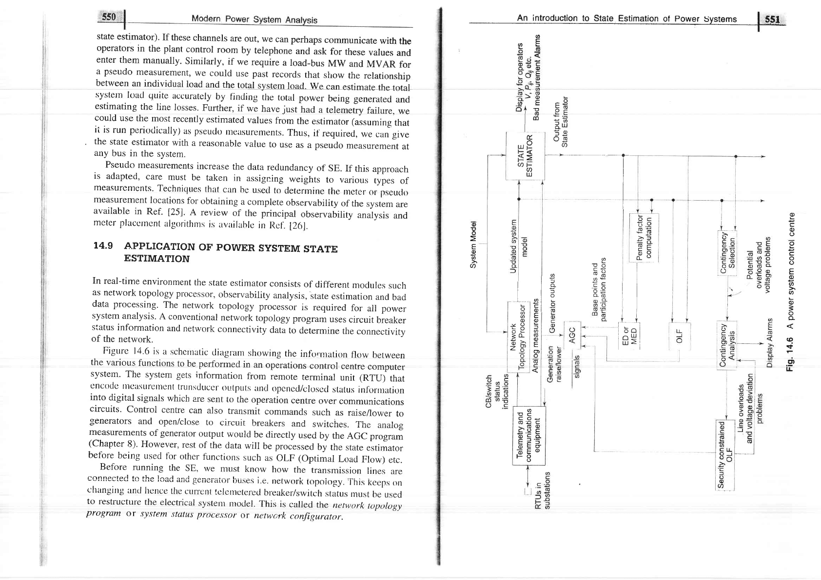
Figtrrc
1r4.6
is
it
schcrnatic
cliagtarn
showing
the
info.rnation
flow
between
the
varior-rs
functions
to
be performed
in
an
operations
control
centre
compurer
system.
The
system
gets
information
from
remote
terminal
unit
(RTU)
that
cncodc
lllcasLlrclllcnt
tl'ullsduccr
0r-rtputs
ancl
opcnccl/closccl
staLus
inlbmration
into
digital
signals
which
are
sent
to
the
operation
centre
over
communications
circuits.
Control
centre
can
also
transmit
commands
such
as
raiseflower
to
generators
and
open/close
to
circuit
breakers
and
switches.
The
analog
measurements
of
generator
output
would
be
rJirectly
used
by the
AGC
program
(Chapter
8).
However,
rest
of
the
data
will
be
processed
by
the
state
estimator
befbre
being
used
fbr
other
functions
such
as
OLF (Optimal
Loacl
Flow)
etc.
Before
running
the
SE,
we
must
know
how
the
transmission
lines
are
r-nnnenfprl fn flro ln^'l ^^J r--- -- - --
L\/
Lrru
r\/cu
(rrrLr
licrrrsr.u.(r
l.,uscli
l.e.
nelworK
topology,
lhrs
kceps
6n
changing
and
hcnce
l.hc
currertt
r.clentetered
breaker'/switch
stertus
must
be
used
to
restructure
the
electrical
system
model.
This
is
called
the
network
tr,tpop.tgy
program
or
system
status proce,\.tor
or
netwc;rk
configurator.
,l
'I
I
An introduction
to
state
Estimation
of
powqr
systems
I
FSI
t-
o
o
o
o
L
c
o
o
E
o
a
U)
L
o
=
o
o
q
sf
E;
ll-
I
o
(!
(E
o
(L
I
I
I
I
I
I
I
I
i
l_
I
nl
LUI
>i
I
I
I
I
I
I
,tl
l6c
io!
LLI
.
L
--9
FG
.Yt
=th
drx
og
a
a
L
n^
vv
a
.nF
A-L
q
'=.o
o
0-(E
I
o
o
E
o
L
f
a
(!
o)
E
o)
o
tr
o
t-
F
a
trJ
]U
F
Cn
I
I
t,-
L
o
a
U)
o
XH
;o-
ii' >,
z8
F
o
1f
o
E
o
o
U)
U)
COe
N'E
C
b8
g
E E.E
EEE
6Eo
FO
o
U'E
bA !
lo
lm
I
ilr
l
Modern
Po
I
The
output of
the
state
estimator i.e. lvl, 6, P,j,
Q,jtogether.
with
latest
model
form the basis for the economic
dispatch
(ED)
or minimum
emission dispatch
(MED),
contingency
analysis
program
etc.
Further Readin
The
weighted least-squares approach
to
problems
of static state estimation
in
power
systems
was introduced by Schweppe
11969-741.
It was earlier
originated
in the
aerospace industry. Since
1970s, state estimators
have been
installed on a regular basis
in nern' energy
(power
system or
load dispatch)
control centres and have
proved quite helpful. Reviews of
the
state
of the art
in state estimation algorithms based on this
modelling approach were
published
by
Bose
and Clements
[27]
and Wu
[28].
Reviews
of
external system
modelling
are available in
1291.
A
generalised
state
estimator with integrated state,
stutus
and
parameter
estimation capabilities
has recently been
proposed
by Alsac
et al
[30].
The new role of state
estimation and other
advanced analytical
functions
in competitive energy markets was
discussed
in Ref.
[31].A
comprehensive
bibliography
on
SE from
1968-89 is available in
Ref.
[32].
PROB
LEMS
14.1 For Ex.
6.6
if the
power
injected
at
buses
are
given
as Sr
=
1.031
-
j0.791,
Sz
=
0.5
+
71.0
and
'S3
=
-
1.5
-
j0.15
pu.
Consider Wt= Wz=
Wz
=
l.
Bus I is a reference
bus. Using
flat
start,
find the estimates of
lV,l and
{.
Tolerance
=
0.0001.
lAns:
Vl
=
l/0", V',
=
t.04223
Final values: Vt
-
1.04./.0", V2
l- 3.736"1.
14.2 For sample
system shown in
Fig.
have
the
followine
characteristics.
Meter
Full scale
(MW)
Accuracy
(MW)
o
(pu)
Fig.
P.14.2
Given
a
single
line
as
shown
in
Fig.
p
14.3,
two
measurements
are
available.
using
DC load
flow,
calculate
the
best
estimate
of
the power
flowing
through
the
line.
14.3
4=
0 rad.
/1 |
(
,r-1--
t
t-----
[l
r
y0.1pu
1
Mt2
(1oo
MVA
base)
Mzt
l-
2
Fig.
P.
14.3
Meter
Full
scale
(MW)
Meter
Standard
Deviation
(
o
)
in
full
scale
Meter
Reading
(Mw)
10.4297",
V\
=
0.9982q
l-2.1864";
=
1.080215 l-1.356, Va
-
1.03831
P. 14.2, assume that the
three meters
Mrz
Mzr
100
100
1
4
32
-26
Mrz
Mtt
Mzz
100
r00
100
+8
+4
+
0.8
0.02
0.01
0.002
the
phase
angles
4
*d d2
given
the
REFEREN CES
Books
l. Mahalanabis,
A.K.,
D.P.
Kothari
and
S.L
Ahson,
Computer
Aidetl
pr;wer
System
Analysis
and
Control,
Tata
McGraw-Hill,
New
Delhi,
19gg.
2.
Nagrath,
I.J. and
D.P.
Kothari,
Power
System
Engineering,
Tata
McGraw-Hill.
Ncw Dclhi,
I
q94.
3.
Mtrnticclli'
A.,
State
li.rtinrution
in
Eler:tric:
Power
Sysrems
A
Gcnerali.recl
Apprct-
at:h,
Kluwcr
Academic
Publishers,
Boston,
1999.
4.
Kusic,
G'L.,
Computer-Aided
Power
Systems
Analysis,
Prentice-Hall,
N.J.
19g6.
5. Wood,
A'J. and
B.F.
Wollenberg,
Power
Generation,
Operation
and
Control.
Znd
Ed., John
Wiley,
NY,
1996.
Calculate
the best
estimate for
f,'11,...,: nmnnf t,
| 1-rl
l\., W | | l5
| I lU{lDLll
t/l I lUl lL,)
Meter
Meusured value
(MW)
Mtz
Mrz
Mt,
70.0
4.0
30.5
An lntroduction
to
State
Estimation
of Power
'l
I
I
j
t-
;554.;l
Modern
Power
System
Analysls
6.
Grainger,
J.J.
and
W.D.
Stevenson,
Power
System
Analysis,
McGraw-Hill,
NY',
1994.
7.
Deautsch,
R.,
Estimation
Theory,
Prentice-Hall
Inc'
NJ,
1965
g.
Lawson,
C.L.
and
R.J.
Hanson,
Solving
Least
Squares
Problens,
Prentice-Hall.
inc.,
NJ.,
i974.
g.
Sorenson,
H.W.,
Parameter
Estimation,
Mercel
Dekker,
NY,
1980'
Papers
10.
Schweppe,
F.C.,
J.
Wildes,
D.
Rom,
"Power System
Static
State
Estimation,
Parts
l, ll
and
lll",
IEEE
Trans',
Vol.
PAS-89,
1970,
pp
120-135'
ll.
Larson,
R.E.,
et.
al.,
"State
Estimation
in
Power
Systems",
Parts
I and
II,
ibid-,
pp
345-359.
lZ.
Schweppe,
F.C.
and
E.J.
Handschin,
"static
State
Estimation
in
Electric
Power
System",
Proc.
of
the
IEEE,
62,
1975,
pp
972-982'
13.
Horisbcrgcr,
H.P.,
J.C.
Richarcl
and
C.
Rossicr,
"A
Fast
Dccouplcd
Static Statc
Estimator
for
Electric
Power
Systems",
IEEE
Trans.
Vol.
PAS-95,
Jan/Feb
1976,
pp 2O8-215.
Monticelli,
A.
and
A. Garcia,
"Fast
Decoupled
Estimators",
IEEE
Trans'
Power
Sys/,
5,
May
1990,
pP
556-564.
Dopazo,
J.F.
et.
al.,
"State
Calculation
of
Power
Systems
from
Line
Flow
Measurcments,
Parts
I and
ll",
IEEE
Trans.,
89,
pp. 1698-1708,
91,
1972,
pp
145-151.
16.
Dcbs,
A.S.
ancl
R.E.
Larson,
"A
Dynamic
Estimator
for
Tracking
the
State
of
a
Power
System",
IEEE
Trans'
89,
1970,
pp 1670-1678'
iZ.
K1u-pholz,
G.R.
et.
al.,
"Power
System
Observability:
A Practical
Algorithm
Using
Nctwork
Topology",
IEEE
Trans.
99'
1980'
pp 1534-1542'
lg.
Sirnoes-Costa,
A
and
V.H.
Quintana,
"A
Robust
Numerical
Technique
for
Power
System
State
Estimation",
IEEE
Trans.
100,
1981,
pp 691-698'
19.
Simgcs-Costa,
A
and
V.H.
Quintana,
"An
Orthogonal
Row
Processing
Algorithm
for
Power
System
Sequential
State
Estimation",
IEEE
Trans.,
100,
1981'
pp
3'79r-3799.
20.
Debs,
A.S.,
"Estimation
of
External
Network
Equivalents
from
Internal
System
Data", IEEE
Trans.,
94,
1974,
pp 1260-1268'
21.
Garcia.
A.,
A.
Monticelli
and
P.
Abreu,
"Fast Decoupled
State
Estimation
and
Bad
Dara
Processing",
IEEE
Trans.
PAS-98,
Sept/Oct
1979,
pp
1645-1652.
22.
Handschin,
E.
et.
al.,
"Bad
Data
Analysis
for
Power
System
State
Estimation",
IEEE
Trans.,
PAS-94,
1975,
pp
329-337-
.t2
r.^-r:6 rJ r or nl
"Flqd
T)cre Detecfion and ldentification". Int. J.
EleC.
POWer,
4J.
r\V6lrrrt
Lt.r.
eL.
@e.,
Vol.
12,
No.
2,
April
1990,
PP
94-103'
24.
Me-Jjl,
H.M.
and
F.C.
Schweppe,
"Bad Data
Suppression
in
Power
System
State
Estimation",
IEEE
Trans.
PAS-90,
1971'
pp
2718-2725'
25.
Mafaakher,
F.,
et.
al,
"Optimum
Metering
Design
Using
Fast
Decoupted
Estimator",
IEEE
Trans.
PAS-98,
7979,
pp
62-68.
14.
15.
i
i
I
An
Introduction
to State
Estrmation of
Power Systems
I
555
_T--
26.
Clements,
K.A.,
"Observability Methods
and optimal
Meter Placement",
Int.
J.
Elec.
Power,
Vol. 12,
no.
2, April 1990,
pp
89-93.
27. BoSe,
A. and Clements,
K.A.,
"Real-time
Modelling
of Power
Networks", IEEE
Proc., Special
Issue
on
Computers
in Power Svstem Operations,
Vol.
75,
No. 12,
Dee
1987;aP
76ff7=1ffi2:
28.
Wu, F.F.,
"Power
System
State
Estimation:
A
Survey",
Int:
J.
Elec. Power and
Energy Syst.,
Vol. 12, Jan
1990,
pp
80-87.
29. Wu,
F.F. and
A. Monticelli,
"A
Critical
Review on
External Network Medelling
for On-line
Security
Analysis",
Int. J.
Elec. Power
and Energy Syst.,
Vol.
5, Oct
1983,
pp
222-235.
30.
Alsac,
O., et.
aI.,
"Genetalized State
Estimation",
IEEE Trans. on Power Systems,
Vol. 13,
No. 3,
Aug. 1998,
pp
1069-1075.
31. Shirmohammadi,
D. et.
al.,
"Transmission
Dispatch
and
Congestion
Management
in
the
Emerging
Energy
Market
Structures",
IEEE Trans.
Power System.,
Vol
13,
No. 4,
Nov 1998,
pp
1466-1474.
32.
Coufto,
M.B.
et. aI,
"Bibliography
on Power System
State Estimation
(1968-
1989)",
IEEE Trans.
Power
Sysr.,
Vol.7,
No.3, Aug. 1990,
pp
950-961.
15.1
INTRODUCTION
For
reduction
of
cost
and
improved
reliability,
most
of
the
world,s
electric
power
systems
continue
to
be
intercor
of
diversity
of
loads,
availability
of
sor
to
loads
at
minimum
cost
and
pollr
deregulated
electric
service
environme
to
the
competitive
environment
of
reli
Now-a-days,
greater
demands
have
been
placed
on
the
transmission
network,
and
these
demands
will
continue
to
rise
because
of
the
increasing
number
of
nonutility
generators
and
greater
competition
among
utilitics
the'rselves.
It
is
not
easy
to
acquire
new
rights
of
way.
Increased
demands
on
transmission,
absence
of
long-term
planning,
and
the
need
to
provide
open
access
to
generating
companies
and
customers
have
resulted
in
less
security
and
reduced
quality
of
supply.
compensation
in
power
systems
is,
therefore,
essential
to
alleviate
some
of
these
problems'
series/shunt
compensation
has
been
in
use
for
past
many
years
to
achieve
this
objective.
In
a power
system,
given
the
insignificant
erectricar
storage,
the
power
generation
and
load
mttst
balance
at
all
times.
To
some
extent,
the
electrical
system
is
self'-regulating.
If generation
is
less
than
roacl,
voltage
ancl
frequency
d'op,
and
thereby
reducing
the
road.
However,
there
is
only
a
few
percent
margin
for
such
self-regulation.
lf
,,^r+--^ :- :_,-
support,
rhen
load
increase
with
con"se;:;iilTi:
,:t#'j|i;l:ffL;
system
collapse'
Alternatively,
if
there
isinadequate
reactive
power,
the
system
rnay
havc
voltage
collapse.
This
chapter
is
devotecl
to
the
stucly
of
various
methods
.f
compensating
power
systems
and
various
types
clf
compensating
crevices,
cailccr
.,,,rrj",rru,urr,
to
alleviate
the
problems
of
power
system
outlined
above.
These
compensators
Compensation
in
lglver
Systems
|
55?
I
can
be
connecteci
in
the
system
in two
ways,
in series
and
irr shunt
at
ihe line
ends
(or
even
in the
midPoint)'
Apart
from
the
well-known
technologies
of
compensation,
the
latest
technology
of
Flexible
AC
Transmission
System
(FACTS)
will
be introduced
towards
the
end
of
the
chaPter.
15.2
LOADING
CAPABILITY
There
are
three
kinds
of
limitations
for
loading
capability
of
transmission
system:
(i)
Thermal
(ii)
Dielectric
(iii)
Stability
Thermal
capabitity
of
an
overhead
line
is
a
function
of
the
ambient
temperature,
wind
conditions,
conditions
of
the
conductor,
and
ground
clearance.
There
is a
possibility
of
converting
a
single-circuit
to
a
double-circuit
line to
increase
the
loading
caPabilitY.
Dieletric
Limitations
From
insulation
point of
view,
many
lines
are
designed
very
conservatively.
For
a
given nominal
voltage
rating
it is
often
possible
to
increase
normal
operating
voltages
by
l07o
(i.e.
400
kV
-
440
kV). One
should,
however,
ensure
that
dynamic
and
transient
overvoltages
are
within
limits.
[See
Chapter
13
of
Ref.
71.
Stability
Issues.
There
are
certain
stability
issues
that
limit
the
tlansmission
capability.
These
include
steady-state
stability,
transient
stability,
dynamic
stability,
frequency
collapse,
voltage
collapse
and subsynchronous
resonance.
Several
goocl books
l,
l, 2,
6,7
,8)
are
available
on these
topics.
The
FACTS
technology
can
certainly
be
used
to
overcome
any of
the
stability
limits, in
which
case
the final
limits
would
be
thermal
and
dielectric'
15.3
LOAD
COMPENSATION
Load
compensation
is
the
management
of
reactive
pcwer to improve
power
quality
i.e.
V
profile
and
pf. Here
the
reactive
power flow
is
controlled
by
installing
shunt
compensating
devices
(capacitors/reactors)
at the
load end
bringing
about
proper balance
between
generated
and
consurned
reactive
power.
This
is
most
effective
in
improving
the
power transfer
capability
of
the
system
ancl
its
voltage
stability.
It is
desirable
both
economically
and
technically
to
operate
the
system
near
uriity
power factor.
This
is
why some
utilities
impose
a
penalty
on
low
pf loads.
Yet
another
way
of
irnproving
the
system
performa-nee
is to
operate it
under
near
balanced
conditions
so
as to
reduce
the
ho*
of
legative
sequence
currents
thereby
increasing
the
system's
load
capability
and
reducing
power
loss'
A
transmission
line
has
thrcc
critical
loadings
(i)
natural
loading
(ii)
steady-
stare
stability
limit
and
(iii)
thermal
limit
loading.
For
a
compensated
line the
natural
loading
is
the
lowest
and
before
the thermal
loading
limit
is
reached,
steady-state
stability
limit
is arrived.
Ideal
voltage
profile
for
a transmission
line
is
flat,
which
can
only
by
loading
the
line
with
its
surge
impedance
loading
while
this
esJ
I
T5.4
LINE
COMPENSATION
compensated,
it
will
behave
as
a
purely
resistive
element
and
would.
cause
series
resonance
even
at fundamental
frequency.
The
location
of series
capacitors
is
decided
by
economical
factors
and
severity
of fault
currents.
Series
capacitor
reduces
line
reactance
thereby
level
of fault
currents.
on
on vanous
lssues
ln
in
series
and
shunt
compensators
now
follows.
15.5
SERIES
COMPENSATION
A
capacitor
in
series
rvith
a line gives
control
over
the
effective
reactance
between
line
ends.
This
effective
reactance
is
eiven bv
Xr=X-X,
where
Xl
=
line
reactance
Xc
=
capacrtor
reactance
It is easy
to see
that
capacitor
rcduccs
the
cffectivc
line
rcactance*.
This results
in improvement
in
performance
of
the
system
as
below.
(i)
Voltage
drop
in
the line
reduces (gets
compensated)
i.e.
minimization
of
end-voltage
variations.
(ii)
Prevents
voltage
collapse.
(iii)
Steady-stttte
power
transfer
increases;
it is
inverscly
proportional
to
Xl.
(iv)
As
a result
of
(ii)
rransient
stability
limit
increasbs.
The
benefits
of the
series
capacitor
compensator
are
associated
with
a
problem.
The
capacitive
reactance
Xg
fbrms
a series
resonant
circuit
with
the
total
series
reactance
X
=
Xt *
X*.n
*
Xoun,
The
natural
frequency
of
oscillation
of this
circuit
is given
by.
f^-
|
rL
2rJrc
be
achieved
may
not
be
achievable,
the
characteristics
of the
line
can
be
modi
so
that
(i)
Ferranti
effect
is
minimized.
(ii)
Underexcited
operation
of
synchronous
generators
is
not
required.
(iii)
The power
transfer
capability
of
the
line
is
enhanced.
Modifying
the
characteristics
of
a line(s)
is
known
as
line
compensation.
Various
compensating
devices
are:
o
Capacitors
.
Capacitors
and
inductors
.
Active
voltage
source (synchronous
generator)
When
a
number
of
capacitors
are
connected
in parallel
to
get
the
desired
capacitance,
it is
known
as a
bank
of
capacitors,
similarly
a Uant<
of
incluctors.
A
bank
of
capacitors
and/or
inductors
can
be
adjusted
in
steps
by
switching
(mechanical). .
Capacitors
and
inductors
as
such
are passive
line
compensators,
while
synchronous
generator
is an
active
compensator.
When
solid-state
devices
are
used
for
switching
off
capacitors
and
inductors,
this
is
regardecl
as
active
compensation.
Before
proceeding
to
give
a detailed
account
of
line
compensator,
we
shall
briefly
discuss
both
shunt
and
series
compensation.
Shunt
compensation
is
more
or less
like
load
compensation
with
all
the
advantages
associated
with
it
and
discussed
in
Section
15.3.
It
needs
to
be
pointed
out
here
that
shunt
capacitors/inductors
can
not
be
distributed
uniformally
along
the
line.
These
are
normally
connected
at the
end
of
the
line
and/or
at
midpoint
of
the
line.
Shunt
capacitors
raise
the
load pf
which
greatly
increases
the power
transmitted
over
the
line
as
it is
not
required
to carry
the
reactive
power.
There
is
a
limit
to which
transmitted
power
can
be
increased
by
shunt
compensation
as
it
would
require
very
iarge
size
capacitor
bank,
which
would
be
impractical.
For
increasing
power
transmitted
over
the
line
other
and
better
means
can
be
adopted.
For
example,
series
compensation,
higher
transmission
voltage,
HVDC
etc.
When
switched
capacitors
are
employed
for
compensation,
these
shculd
be
disconnected
irnmediately
under
light
loacl
conclitions
to
avoicl
er.cessive
voltage
rise
and
ferroresonance
in
presence
of transformers.
The purpose
of
series
compensation
is
to
cancel
part
of the
series
inductive
reactance
of the
line
using
series
capacitors.
This
helps
in
(i)
increase
of
maximum
power
transfer (ii)
reduction
in power
angle
for a given
amount
of
power
transfer (iii)
increased
loading.
From
practical
point
of view,
it
is
'2n
where
l=
system
frequency
xReactive
voltage
drops
of a
series
reactance
added
in
a line
is I2x
It is
positive
if
X is inductive
and negative
if
X
is capacitive.
So
a
series
capacitive
reactance
reduces the
reactance
voltage
drop
of
the
line,
which
is
an
alternative
wav
of
saying
that
X't=
\-
X,-
I
ii
ti
ti
I
fc<f
which is
subharmonic
oscillation.
Even
though
series
compensation
has often
been
found
to be
cost-effective
compared
to
shunt
compensation,
but sustained
oscillations
below
the
funda-
mental
system
frequency
can
cause
the
phenomenon,
referred
to aS
subsynchronous
resonance
(SSR)
first
observed
in 1937,
but
got world-wide
attention
only
in
the 1970s,
after
two
turbine-generator
shaft
failures
occurred
at
the
Majave
Generating
station
in
Southern
Nevada.
Theoretical
studies
pointed out
that
interaction
between
a series
capacitor-compensated
line,
oscillating
at
subharmonic
frequency,
and
torsional
mechanical
oscillation
of
turbine-generator
set
can result
in
negative
damping
with
consequent
mutual
reinforcement
of
the
two
oscillations.
Subsynchronous
resonance
is
often
not a
major
problem,
and
low
cost countermeasures
and
protective
measures
can be
applied.
Some
of
the
corrective
measures
are:
(i)
Detecting
the low
levels
of
subharmonic
currents
on
the
line
by
use
of
sensitive
relays,
which
at
a certain
level
of
currents
triggers
the
action
to
bypass
the
series
capacitors.
(ii)
Modulation
of
generator
field
current
to
provide increased
positive
damping
at
subharmonic
frequency'
Series
incluctors
are neeclecl
for line
compensation
under
light
load
conditions
to
counter
the
excessive
voltage
rise
(Ferranti
effect).
As
the
line
load
and,
in
particular
the
reactive
power flow
over
the line
varies,
there
is
need to
vary
the
compensation
for
an acceptable
voltage
profile.
The
mechanical
switching
arrangement
for
adjusting
the capacitance
of the
capacitor
bank
in
series
with
the
line
is
shown
in Fig.
15.1.
Capacitance
is
variecl
by opening
the
switchos
of
individual
capacitances
with
the
capacitance
C1,
being
started
by a
bypass
switch.
This
is
a step-u'ise
arrangement.
The
whole
bank
can
also be
bypassed
by
the starting
switch
under
any
emergent
conclitions
on
the line.
As
the switches
in
series
with
capacitor
are current
carrying
suitable
circuit
breaking
arrangement
are
necessary.
However,
breaker
switched
capacitors
in
series
are
generally avoided
these
days
the,capacitor
is
either
fixed
or
thvristor
switched.
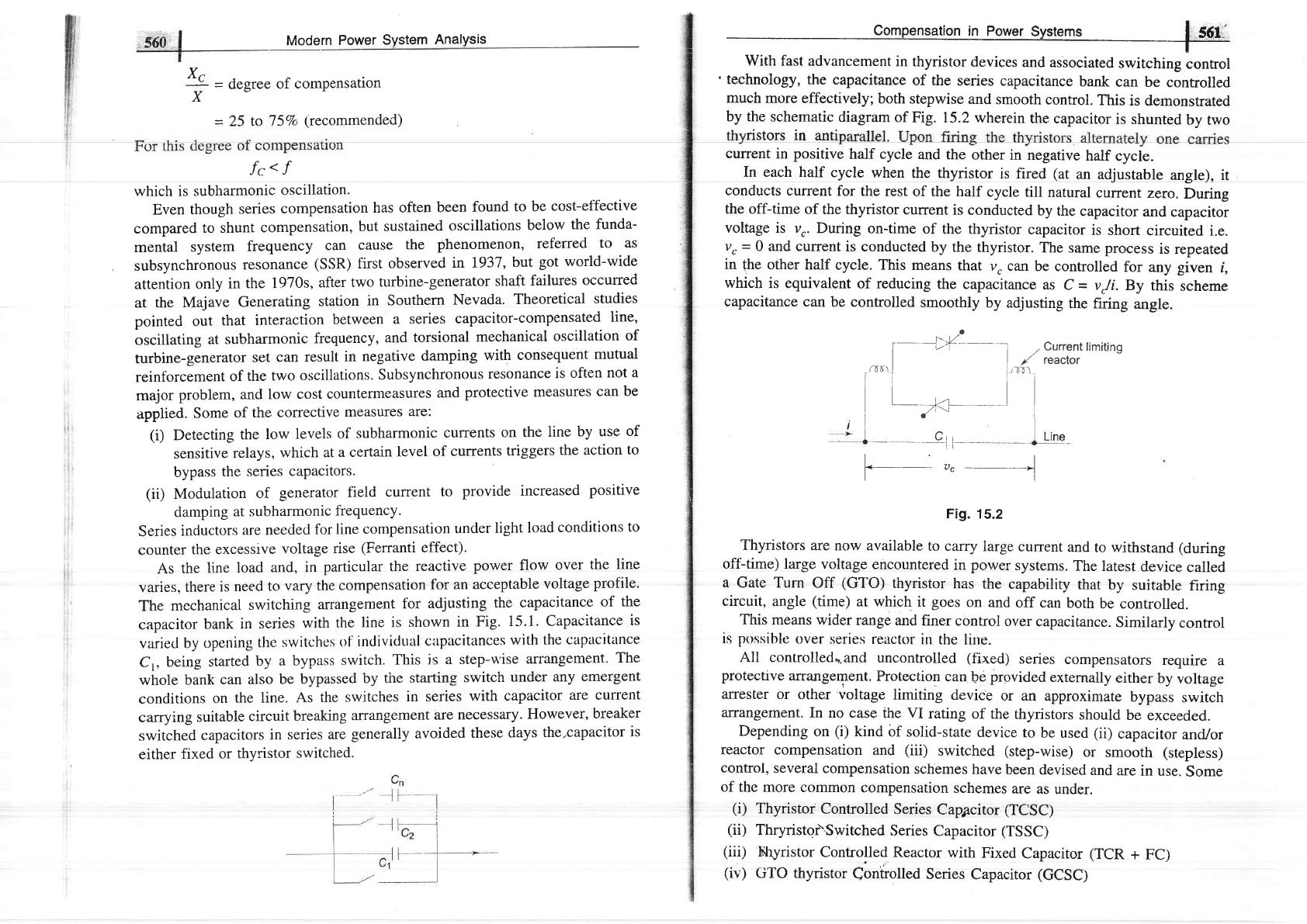
I
,,
'
technology,
the
capacitance
of the
series
capacitance
bank
can
be
controlled
much
more effectively;
both
stepwise
and
smooth
control.
This
is
demonsffated
by the
schematic
diagram
of Fig. 15.2
wherein
the capacitor
is shunted
by two
nstors
ln antl
current
in
positive
half
cycle
and the
other
in negative
half
cycle.
In each half cycle
when
the thyristor
is fired
(at
an
adjustable
angle), it
conducts
current
for
the rest
of the half
cycle till
natural
current
zeto.
During
the
off-time of the
thyristor
current
is
conducted
by the
capacitor
and
capacitor
voltage is vr.
During
on-time
of the thyristor
capacitor
is
short
circuited
i.e.
v,
=
0 and current
is conducted
by the
thyristor.
The
same process
is
repeated
in the
other half
cycle. This
means
that
v, can
be
controlled
for
any
given
i,
which
is equivalent
of reducing
the capacitance
as
C
=
vJi.By
this
scheme
capacitance can
be controlled
smoothly
by
adjusting
the firing
angle.
l--+{--_-__-a,.Currenuimitins
| | r'
reactor
^o'll""i
l-1<-------r
l
Cri
---.
i
t
7,c
-----]
Fig.
15.2
Thyristors
are now
available
to carry
large
current
and
to withstand (during
off-time) large
voltage
encountered
in
power
systems.
The
latest
device
called
a Gate Turn Off
(GTO)
thyristor
has
the
capability
that
by
suitable
firing
circuit,
angle
(time)
at which
it
goes
on
and
off can
both
be controlled.
This
means wider
range and
finer
control
over
capacitance.
Similarly
confrol
is
possible
over series
reactor
in
the line.
All controlled.".?nd
uncontrolled
(fixed)
series
compensators
require
a
protective
arrangement.
Protection
can
be
provided
externally
either
by
voltage
arrester
or other
voltage
limiting
device
or
an approximate
bypass
switch
arrangement.
In no case
the VI
rating
of the
thyristors
should
be
exceeded.
Depending
on
(i)
kind
of
solid-state
device
to
be
used
(ii)
capacitor
and/or
reactor
compensation
and
(iii)
switched
(step-wise)
or smooth (stepless)
control,
several compensatron
schemes
have
been
devised
and
are
in
use.
Some
of the more
common
compensation
schemes
are as
under.
(i)
Thyristor
Controlled
Series
Cappcitor
(TCSC)
(ii)
Thryristor\Switched
Series
Capacitor
(TSSC)
(iii)
Fllyristor
controlled
Reactor
with
Fixed
capacitor
(TCR
+
FC)
(iv)
GTO thyristor
Coniiolled
Series
Capacitor
(GCSC)
Modern
Power
System
AnalYsis
rL
=degree
of
compensation
X
=
25 to
J5Vo
(recommended)
i'r
;
*562i
I
Modern
Power
System
Analysis
I
(v)
Thyristor
Controlied
reactor
(TCR)
Capacitor
and/or
reactor
series compensator
act
to modify
line impedance.
An
altcrnativo
approach
is
to introducc
a
controllable
voltagc
sourcc
in series
with the line.
This
scheme
is known
as
static synchronous
series
compensator
(SSSC).
SSSC
has the
capabitity
to
induce
both
capacitive
and
inductive
voltage ln senes
wrtn [lne,
wrdenrng
me operatmg
reglon
o
It can
be
used for
power
flow
control
both
increasing
or
decreasing
reactive
flow
on
the
line. Further
this scheme
gives better
stability
and is more
effective
in
damping
out
electromechanical
oscillations.
Though
various types
of compensators
can
provide highly
effective
power
flow
control,
their operating
characteristics
and
compensating
features
are
different.
These
differences
are
related
to their
inherent
attributes
of their
control
circuits;
also
they
exhibit
different
loss characteristics.
From the
point of
view of
almost
maintenance
free
operation
impedance
modifying
(capacitors and/or
reactors)
schemes
are superior.
The
specific
kind
of compensator
to
be employed
is
very much
dependent
on
a
particular
application.
15.6
SHUNT
COMPENSATORS
As already
explained
in
Sec.
15.4
and
in Ch. 5
(Sec.
5.10)
shunt
compensators
are
connected
in
shunt
at
various
system
nodes
(major
substations)
and
sometimes
at mid-point
of
lines.
These
serve
ihe
purposes of voltage
control
and
load
stabilization.
As
a result
of
installation
of shunt
compensators
in
the
system,
the
nearby
generators
operate
at near
unity
pf
and
voltage
emergencies
mostly
clo
not
arise.
The two
kinds
of
compensators
in
use
are:
(1)
Static
var
compensators
(SVC):
These
are banks
of capacitors
(some-
times
incluctors
also
fgr
use
under
light
load conditions)
(ii)
STATCOM:
static
synchronous
compensator
(iii)
Sync
hronous
condenser:
It
is
a synchronous
motor
running
at
no-load
and having
excitation
adjustable
over
a wide
range.
It
f'eeds
positive
VARs
into
the line
under overexcited
conditions
and
negative
VARS
when
underexcited.
(For
details
see
Sec. 5.10.)
It
is
to be
pointed
out
here
that
SVC
and
STATCQM
are
stgtic
var
generators
which
are
thyristor
controlled.
In this
section
SVC
will be
detailed
while
STATCOM
forrns
a
part of FACTS
whose
operafion
is explained
in
Sec.
15.lO.
Statia
VAR Compensator
(SVC)
These
comprise
capacitor
bank
fixed
or switched
(controlled)
or
fixed
capacito
bank
and switched
reactor bank
in
parallel.
These
compensators
draw
reactiv
(leading
or
lagging)
power*
from
the line
thereby regulating
voltage,
improv
*A
rcrrctlrrcc
cor)ncctcd
in shunt to tinc at
voltage
V draws
reactive
power
Vzl]
It is negative
(leading)
if reactance is capacitive
and
positive
(lagging)
if reactance is
inductive.
called
static
var
switches
or systems.
It
means
that
terminology
wise
SVC
=
SVS
and
we
will
use
these
interchangeably.
Basic
SVC
Configrurations
(or
Desigrns)
Thyristors
in
antiparallel
can
be
used
to
switch
on
a capacitor/reactor
unit
in
stepwise
control.
When
the
circuitary
is
designecl
ro
adjust
the
firing
angle,
capacitor/reactor
unit
acts
as
continuously
variable
in
the power
circuit.
Capacitor
or
capacitor
and
incluctor
bank
can
be varied
stepwise
or
continuously
by
thyristor
control.
Several
important
SVS
configurations
have
been
devised
and
are
applied
in
shunt
line
compensation.
Some
of
the
static
compensators
schemes
are
discussed
in
what
follows.
(i)
Sutu.rutcd
reuctlr
This is
a
multi-core
reactor
with
the
phase
windings
so arranged
as
to
cancel
the
principal
harmonics.
It is
consiclered
as
a constant
voltageieactive
source.
It is
almost
maintenance
free
but
not
very
flexible
with
reipect
to
operating
characteristics.
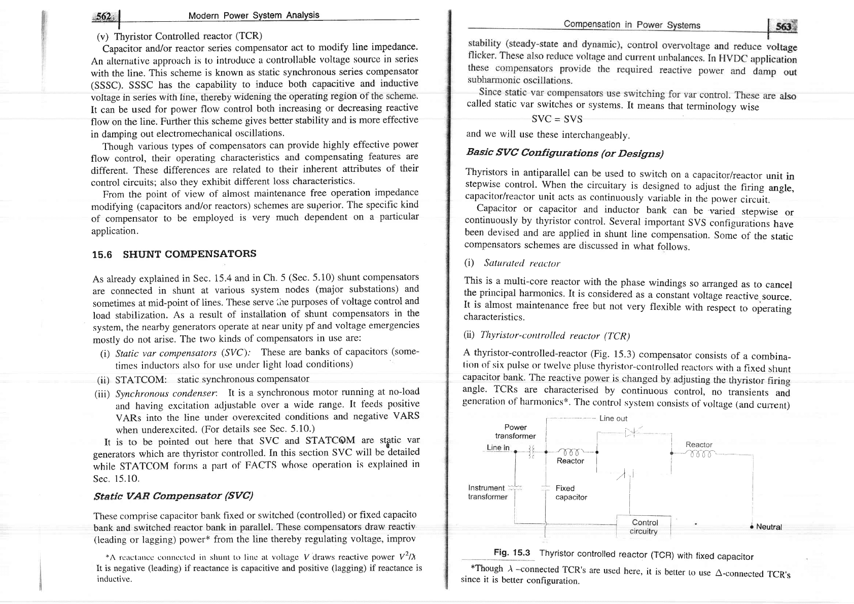
(ii)'fhyristor-coilrroll,cd
reuctor (T'CR)
A thyristor-controlled-reactor
(Fig.
15.3)
compensator
consists
of
a combina-
tion
of six
ptrlse
or twelve
pluse
thyristor-controllecl
reactprs
with
a
fixe<t
shunt
capacitor
bank.
The
reactive
power
is
changect
by
adjusting
the
thyristor
firing
angle.
TCRs
are
characterised
by
continuous
control,
no
transients
and
gencration
of harmonics'k.
The
control
systenr
consists
of
voltage
(and
current)
Power
I
-
-
Line
oi.rt
transformer
I
-?
{-rf
'--
l
neaitr
i
I
Fixed
caoacitor
I
i]
l.:
)tl
I
I
I
I n"r.to,
f
=..'x',rnc.-
-
I
uvvv
I
I
Neutral
Fig.
15.3
Thyristor
controlled
reactor
(TCR)
with
fixed
capacitor
*Though
)
-connected
TCR's
are
since
it
is
better
configuration.
used
here,
it
is
better
to
use
A-connected
TCR,s
Modern Power
System Analysis
measuring
devices, a controller
for error-signal
conditioning, a Iinearizing
circuit
and
one or more synchronising circuits.
(iii)
Thyristor
switcherl capacitor
(fSC)
It
consists
of only a thyristor-switched
capacitor
bank which is split into a
numDer
o unrts o equal ratrngs to
achreve a stepwise con
|;
fe"
system
(e.9.
line
faults,
load
rejection
etc)
TSC/TCR
combinations
are
characterised
by
continuous
contrdl,
no
transients,
low generations
of harmon-
ics,
low
losses,
redundancy,
flexible
control
and
operation.
in
Table
15.1.
Table
15.1
Comparison
of
Static Var
Generators
'0d6'
/
Type
of
Var
Generator
TCR.FC
(1)
TSC-(TSR)
(2)
TCR-TSC
(3)
Damping
reactor
-
Fig. 15.4 Thyristor
switched capacitor
(TSC)
As
such they are applied as a
discretly
variable
reactive
power
source, where
this type
of voltage
support is deemed adequate.
All switching takes
place
when
the voltage
across
the thyristor valve is zero,
thus
providing
almost transient
tree switching.
Disconnection is
eff'ected by
suppressing the firing
plus
to the
thyristors,
which will block when
the current reaches
zero. TSCs are,
charetcLorisccl
by stcp wisc control, no
transients, vcry
low htlrnronics, low
losses,
redundancy
and flexibility.
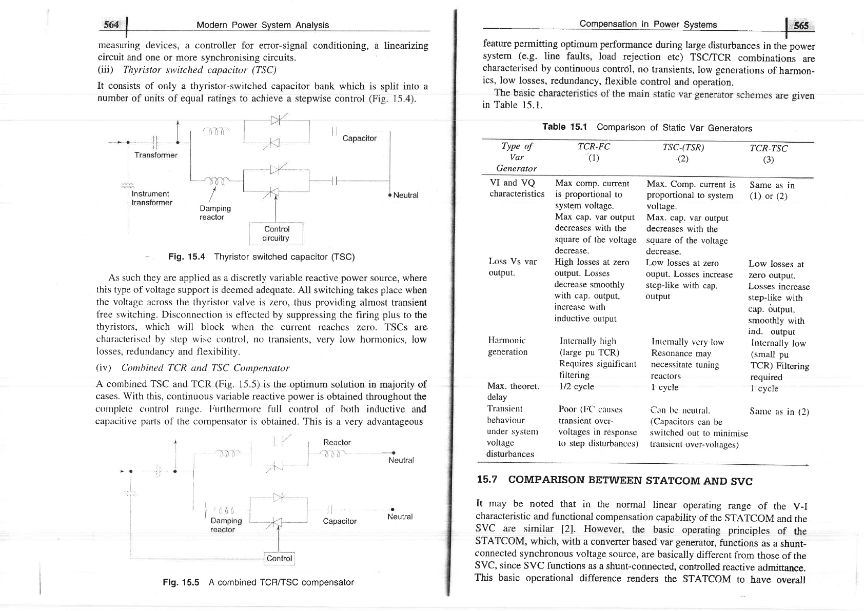
(iv)
Combined TCR and TSC
Compensator
A combined
TSC and
TCR
(Fig.
15.5) is the
optimum solution in majority of
cases.
With
this,
continuous variable reactive
power
is obtained tirroughout
the
cotttl;lctcr conllol
rlngc. Fru'tltclrnorc
lirll control
o1'botlr inductive and
capacitive parts
of the cornpensator
is obtained.
This is a very advantageous
---{
Neutral
ll
Capacitor
T5.7
COMPARISON
BETWEEN
STATCOM
AND
SVC
It mqw he nnterl thot i- tho nnr,-,'l l;-^^- ^*^-,-f:^- ^r -r- - r t t
"'*J
rrrqL
rrr Lrrv rrvlrllal
lrlrt/q.r
\,Pgr4trlrE
rdlrBc
ul
ule
v
-l
characteristic
and functional
compensation
capability
of the
STATCOM
and
the
sVC aie
similar
l2l.
However,
the basic
operating
principles
of
the
STATCOM,
which,
with
a converter
based
var
generator,
functions
as
a
shunt-
connected
synchronous
voltage
source,
are
basically
different
from
those
of
the
SVC, since
SVC functions
as a shunt-connected,
controlled
reactive
admittance.
This basic
operational
difference
renders the
STATCOM
to
have
overall
VI
and
VQ
characteristics
Loss
Vs var
output.
Hannorric
generation
Max.
theoret.
delay
Trrnsir:nl
behaviour
under
systent
voltagr:
disturbances
Max comp.
current
is
proportional
to
system
voltage.
Max
cap. var
output
decreases
with
the
square
of the
voltage
decrease.
High losses
at
zero
output. Losses
decrease
smoothly
with cap.
output,
increirse
with
inductive
output
Intcrnally
high
(large
pu
TCR)
Requires
significant
filtering
l/2 cycle
Poor
(FC
('iluscs
transient
over-
voltages
in response
to step disturbances)
Max.
Comp. current
is
Same
as
in
proportional
to
system (1)
or
(2)
voltage.
Max.
cap.
var
output
decreases
with
the
square
of the voltage
decrease.
Low losses
at
zero
Low
losses
at
ouput.
Losses
increase
zero
output.
step-like
with
cap.
Losses
increase
output
step-like
with
cup.
output,
smoothly
with
ind.
output
hrtcrnally
vcry
low
Internally
low
Resonance
may
(small
pu
necessirate
tuning
TCR)
Filtering
reactors
required
I cycle
I cvcle
Cun
bc lrcutral.
Sanrc
as
in
(2)
(Capacitors
can
be
switched
out to
minimise
trattsicnt
ovcr-volt
ages)
a
Neutral
Fig.
15.5
A
combined TCR/TSC compensator