Kothari D.P., Nagrath I.J. Modern Power Systems Analysis
Подождите немного. Документ загружается.

lil.
Postfault
With
the faulted
line switched
off,
J;=:::,J;2
-055
1.1x1
.
I
=
::: t'-'
sin
d
=
2.0
sin
d
Let us choose
Al
=
0.05 s
The
recursive
relationshi'ps
for
step-by-step
swing
reproduced
below.
Pa(n_r)=
P^
-
P**
sin
4_r
L6n=
L6n-t
*
(Lt)z
o '
M
'
a(n-l)
6n=
6n-t + A,6n
curve
calculation
are
(iv)
(v)
(vi)
Since
there is a discontinuity
in
P, and hence
in
Po, the
average value
of
po
must
be used
for
the first
interval.
P"(0-)
=
0
pu
and Po
(0*)
=
0.9
-
0.88
sin
2I.64"
=
0.576
pu
Po(ouu.,us"l
=
9t#ZQ
=
0.288
pu
L
Sustained
Fault
Calculations
are
carried
out
in Table
12.2
in
accordance
with
the recursive
relationship
(iv), (v)
and
(vi)
above.
The second
column
of the table
shows P-*
the
maximum power
that
can
be transferred
at time
r
given
in
the first
column.
Pn
*
in
the case
of a
sustained
fault
undergoes
a
sudden change
at t
=
0* and
remains
constant
thereafter.
The procedure
of calculations
is illustrated
below
by
calculating
the
row
corresponding
to t
=
0.15 s.
(0'l
sec)
=
31.59"
P."*
=
0.88
sin d
(0.1
s)
=
0.524
P,
(0.1
s)
=
P,,,u*
sin 6
(0.1
s)
=
0.88
x
0.524
-
0.46I
P,
(0.1
s)
=
0.9
-
0.46I
-
0.439
(
At\2
YP,
(0.1
s)
=
8.929
x
0.439
-
3.92
M
6
(0.1s
s)
=
Ad
(0.1
s) +
qL
P,
(0.1
s)
MU\
=
J.38" +
3.92"
=
11.33"
d
(0.15
s)
=
d
(0.1
s) +
Ad
(0.15
s)
=
31.59"
+
11.30'
=
42.89"
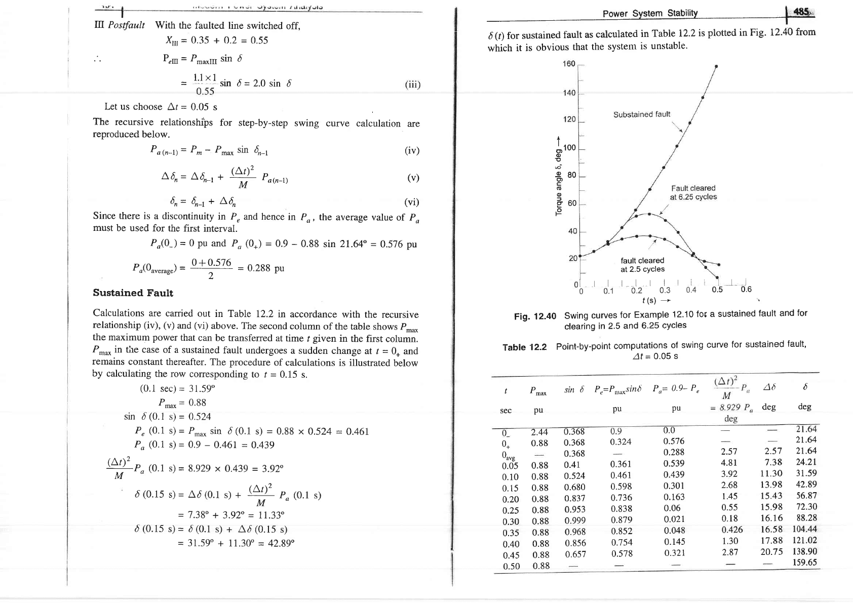
which
it
is
obvious
that
the
systern
is
unstable'
fault cleared
at 2.5
cycles
Itlltlllii
o
0.1
0.2
0.3
0.4
_rl
f
(s)
--
0.5
0.6
Fig.
12.40
Swing
curyes
for
Example
12.10
for a
sustained
fault
and
for
clearing
in
2.5
and
6.25
cYcles
!A A n^i-. l-., ^aia* rratinnc n{ crrrinn nrrn/a fnr
qtrctainarl
fattlt
aaDle
aZ.Z
fUllll'-Uy-Pulllt
t/vlllPutqrrvrro
vr
er'rrrV
vu'
/f
=
0.05
s
t
;100
o
E
@
o80
o)
c
(5
o
ioo
P
t
P^u
sin
6
P"=Prrr,*sin6
P,,=
0'9-
P,
sec
pu
Pu
Pu
a66
deg
deg
2.44
0.88
0.88
0.88
0.88
0.88
0.88
0.88
0.88
0.88
0.88
0.88
0.368
0.368
0.0
0.576
2.57
4.8r
3.92
2.68
r.45
0.55
0.18
0.426
1.30
2.87
2.57
7.38
11.30
13.98
15.43
15.98
r6.r6
16.58
r7.88
20.75
2r.64
2r.64
74.21
31.59
42.89
56.87
72.30
88.28
r04.44
r2r.02
138.90
1s9.65
0+
o^u,
0.05
0.10
0. t5
0.20
0.25
0.30
0.35
0.40
0.45
0.50
0324
0.361
0.46r
0.598
0.736
0.838
0.879
0.852
0.154
0.578
0.368
0.41
0.524
0.680
0.837
0.953
0.999
0.968
0.856
0.657
0.288
0.539
0.439
0.301
0.163
0.06
0.021
0.048
0.145
0.32r
I
Modern
po@is
f-
F.attlt Flaae^'J :- o E n---t--
- su.a
vtcrete.t
tlt
A,i, fryCIeS
Time
to
clear
f'ault
=
2.5
=
0.05
s
50
P-u^
suddenly
to
2.0
at
t
=
0.05-.
Since
the
be
assumed
to remain
constant
fr-om
0.025
s
to
0.075
s.
The
rest
of
the
prtrcedure
is
the
same
ancl
complete
calculations
are
shown
in
Table
12.3.
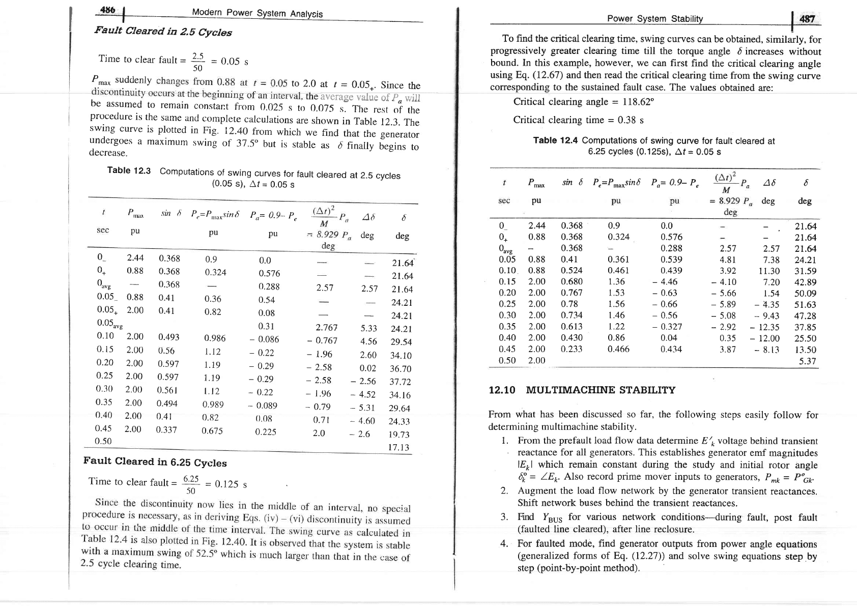
The
swing
curve
is plotted
in
Fig.
12.40
from
which
we
find
that
the
generator
undergoes
a
maximum
swing
of
37.5"
but
is
stable
as
c5 finaily
begins
to
decrease.
Table
12'3
Computations
of
swing
curyes
for
fautt
cleared
at2.s
cvcles
(0.05
s),
At
=
0.05
s
6
deg
P,,,,,^
pu
.sin.
5
Pr,=P,rr.,*,tin5
pr,=
0.9-
pu
pu
pu
A6
deg
0
0.
T
ouu,
0.05
0.05+
0.05uus
0.10
0.i5
o.20
0.25
0.30
0.35
o.40
0.45
0.50
2.44
0.368
0.88
0.368
0.368
0.88
0.41
2.00
0.41
0.0
0.576
0.288
0.54
0.08
0.31
-
0.086
-
0.22
-
0.29
-
0.29
-
0.22
-
0.089
0.08
0.225
0.9
0.324
0.36
0.82
0.986
I.t2
T.I9
r.t9
I.t2
0.989
0.82
0.615
2.57
2.57
21.64
21.64
21.64
24.21
24.21
24.21
29.54
34.10
36.70
37.72
34.16
29.64
24.33
19.73
17.13
2.00
Z.UU
2.00
2.00
2.00
2.00
2.00
2.C0
0.493
0.56
0.s91
0.597
0.561
0.494
0.41
0.337
2.767
5.33
-
0.767
4.56
-
1.96
2.60
-
2.s8
0.02
-
2.58
-
2.56
-
1.96
_
4.52
-
0.79
_
5.31
0.71
-
4.60
2.0
-
2.6
Fault
Cleared
in
6.25
Cycles
Time
to
clear
fault
=
ua?t
=
0.125
s
s0
ltr
progressively greater
clearing time
till the
torque
angle
d increases
without
bound. In this example, however,
we can first
find
the critical
clearing
angle
using Eq.
(12.67)
and then
read
the critical
clearing
time from
the
swing curve
corresponding
to the sustained fault case.
The
values
obtained
are:
Critical clearing angle
=
118.62
Critical clearing
time
=
0.38
s
Table 12.4
Computations
of swing
curve for
fault cleared
at
6.25 cycles
(0.125s),
Af
=
0.05
s
P,no
pu
sin 6
P"=P^
*sin6
Po=
0.9- P"
466
deg
deg
0 2.44
0+ 0.88
ouu,
0.05 0.88
0.10 0.88
0.15 2.O0
0.20 2.00
0.25
2.00
0.30
2.00
0.35
2.00
0.40
2.00
A A? '\N
u.4J Z.W
0.50
2.oo
0.368
0.368
0.368
0.41
0.524
0.680
0.767
0.78
0.734
0.613
0.430
u. z-1-1
0.9
0.324
0.36r
o.46t
1.36
1.53
1.56
1.46
r.22
0.86
u.4c)0
0.0
0.576
0.288
0.539
0.439
-
4.46
-
0.63
-
0.66
-
0.56
-
0.327
0.04
u.4-J4
2.57
4.81
3.92
-
4.10
-
5.66
-
5.89
-
5.08
-
2.92
0.35
-r.6 /
.
2r.&
21.64
2.57
zt.U
7.38
24.2r
11.30
3t.59
7.20
42.89
r.54
50.09
-
4.35
51.63
-
9.43
47.28
-
12.35
37.85
-
12.00
25.50
-
u. t-J l_J.)u
5.37
T2.TO
MULTIMACHINE STABITITY
From
what has been discussed so far,
the following
steps
easily
follow for
determining multimachine
stability.
1.
From
the
prefault
load flow
data determine
E/ovoltage behind
transient
.
reactance
for all
generators.
This establishes
generator
emf
magnitudes
lEll which remain
constant
during the
study and
initial
rotor
angle
6f
=
lEt. Also record
prime
mover
inputs
to
generators,
P*o
-
PoGk
2. Augment
the
load flow network
by the
generator
transient
reactances.
Shift network buses behind the transient
reactances.
3.
End Inus
for
various
network conditions*during
fault,
post
fault
(faulted
line cleared), after line reclosure.
4. For faulted mode, find
generator
outputs from
power
angle
equations
(generalized
forms
of Eq.
(12.27))
and
solve swing
equations
step,by
step
(point-by-point
method).
4ffi
|
Modern
power
System
Analysis
5. Keep
repeating
the
above
step
for post
fault
mode
and
after
line
reclosure
mode.
6. Examine
d(r)
plots
of
all
generators
and
establish
the
answer
to
the
stability
question.
The
above
stgps
are illustrated
in
the
following
example.
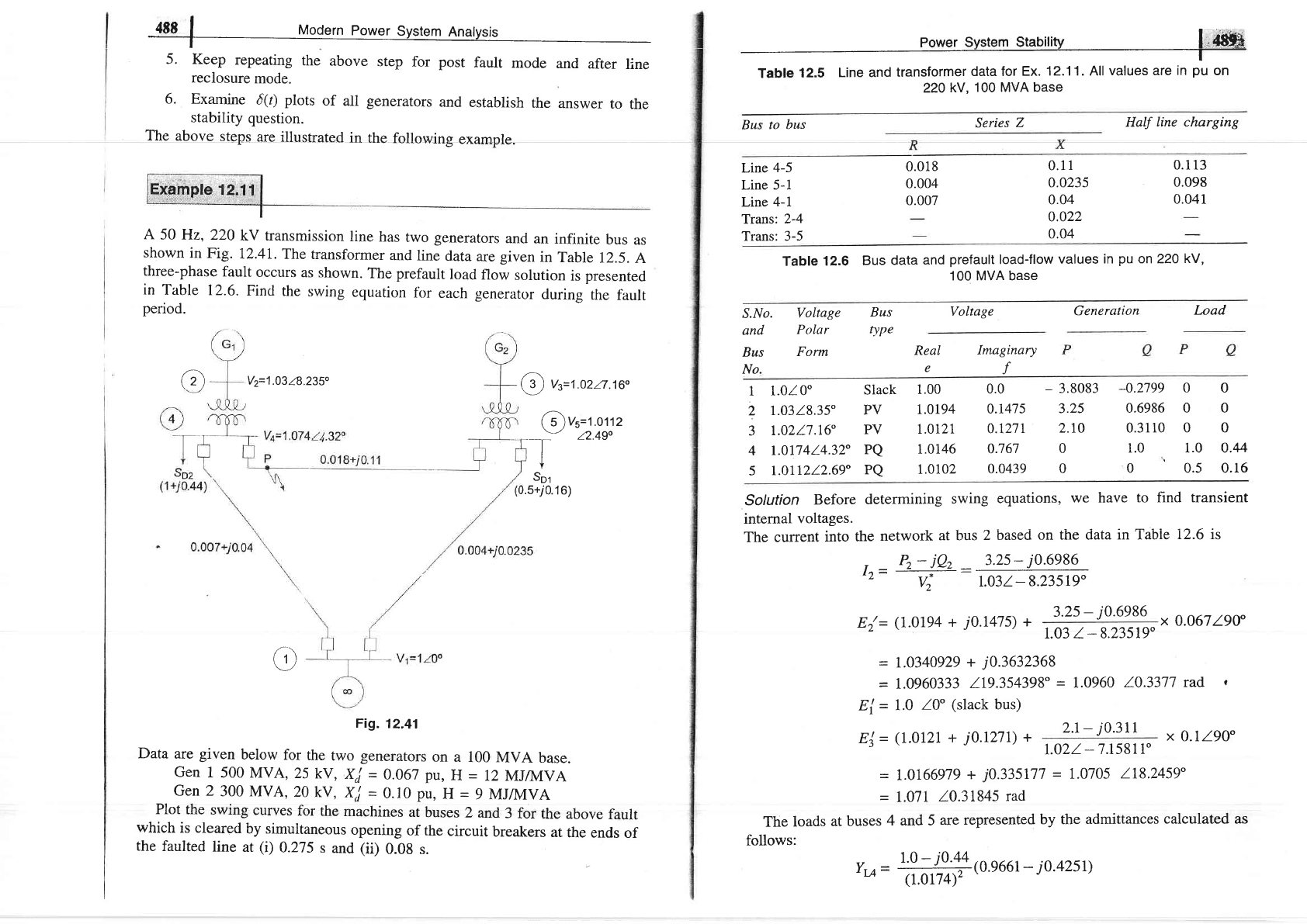
A
50 Hz,
220
kV transmission
line
has
two
generators
and
an
infinite
bus
as
shown
in Fig.
12.4I.
The
transformer
and
line
data
are given
in
Table
I2.5.
A
three-phase
fault
occurs
as shown.
The prefault
load
flow
solution
is
presented
in
Table
12.6.
Find
the
swing
equation
fbr
each generator
cluring
the
fault
period.
o
Vz=1.0328.2350
o
(
l-l
-i
Se
).5+j(
F1.O217.16o
)vs=1.ollz
22.490
6)
)vi
[5,
t-
I'
i6,u
o
Fig.
12.41
Data
are
given
below
for
the
two
generators
on
a
100
MVA
base.
Gen
1
500
MVA,
25
kV,
XJ
=
0.067 pu,
H
=
12
MJAyIVA
Gen 2
300
MVA,
20
kV,
X,j
=
0.10
pu,
H
=
9 MJA4VA
Plot
the
swing
curves
for
the
machines
at
buses
2
and
3
for
the
above
fault
which
is cleared
by simultaneous
opening
of the
circuit
breakers
at
the
ends
of
the
faulted
line
at
(i)
0.275
s
and
(ii)
0.0g
s.
l,,m
220kV,100
MVA base
Bus
to bus
Series
Z
HaIf
line charging
Line
4-5
Line
5-1
Line
4-I
Trans;2-4
Trans:
3-5
0.018
0.004
0.007
0.1r
0.0235
0.04
o.022
0.04
0.113
0.098
0.041
Tabfe
12.6
Bus
data
and
prefault
load-flow
values in
pu
on 220
kV,
100
MVA base
S.No.
Voltage
and
Polar
Bus
Form
No.
Bus
Upe
Voltage
Generation
Load
Real
Imaginary
ef
|
1.010"
Slack
2
t.0318.35"
PV
3
t.0217.16
PV
4
1.017414.32"
PQ
51.011212.69"
PQ
0.0
-
3.8083
0.1475
3.25
0.1271
2.10
0.167
0
0.0439
0
-0.2199
0
0
0.6986
0 0
0.3110
0 0
1.0 1.0 0.44
0 0.5 0.16
1.00
t.0194
1.0121
1.0146
1.0102
Solution
Before
determining
swing
equations,
we have
to find transient
internal
voltages.
The
current
into
the
network
at bus
2 baseci
on the <iata
in Tabie
i2.6 is
r-_
Pr-iQ,
_
3.25-i0.6986
'z
v:
r.o3l-
8.23519"
E{=
(1.0194
+
j0.1475)
+
3.2s
-j0.6986
x
0.06719V
r.03 l-8.23519'
=
1.0340929
+
j0.3632368
=
1.0960333
119.354398"
=
1.0960
lo.337l
tad
I
El
=
I.0
l0'
(slack
bus)
E4
-
Q.0I2r
+
j0.1271)
+
2.1-
j0.31
r
x
0.1 l9O"
r.021-
7.15811'
=
1.0166979
+
j0.335177
=
1.0705
lI8'2459"
-
1.071
10.31845
rad
The
loads
at buses
4 and 5
are represented
by the
admittances
calculated as
follows:
yr
r.=
''9
.!.:,0!
(0.9661
-
jo.4zsr)
6
(1.0174)"
;;'#;;"J###::
il::H,:T:|, :::,::::^'l:,::,1,:nt
reactanles
of
the
machines
we
wlr,
we
wlll,
therefore'
now
designate
as
buses
2
and3,
the
fictitious
internal
nodes
between
the
internal
voltages
and
the
transient
reactances
of
the
machines.
Thus
we
get
Y-^
=
-22-@=-irr.236
Yzq=
j11.236
=
yqz
Ytt
=
io'04+io]
=
-
i7'143
Yzs
=
j7.I43
=
yst
Yu=
Ytq+
yqt*
yqs+
*
Yzq
=
0.9660877
-
j0.4250785
+
4.245
-
j24.2571
+
1.4488
_
i8.8538+
j0.041
+rO.113_
jrt.235g
_
6.6598977
_
j44.6179
Yss=
Yrs*
Ysq*
Ysr*
9*
Ur,
* r",
2
2
'
'35
-
0.4889
-
j0.1565
+
r.4488
-
j8.8538
+
7.039r
_
j41.335
+
/O.1
13
+
j0.098 _
j7.t42}
_
8.97695s
_
js7.297202
The
complete
augmented
prefault
lzuu,
matrix
is
show
n.iri'Table
12.1.
Table
12.T
The
augmented
prefaurt
bus
admittance
matrix
for
Ex.
12.11,
admittances
in pu
I
a,grr,
Power
System
Stability
_ .
During Fault Bus
Matrix
Since
the fault is near bus
4,
it must be short circuited
to
ground.
The
Ynus
during the
fault
conditions
would, therefore, be
obtained by deleting
4th
row
and 4th column from the above
augmented
prefault
Y".r. rnatrix.
Reduced
fault
matrix
(to
the
generator
internal nodes) is obtained
by eliminating
the new
4th
row and column
(node
5)
using
the relationship
Y*iqn"*1
=
Y*j@tat
-
Y
t n(oltt)
ynj(old
)/
Y
rn
@ta)
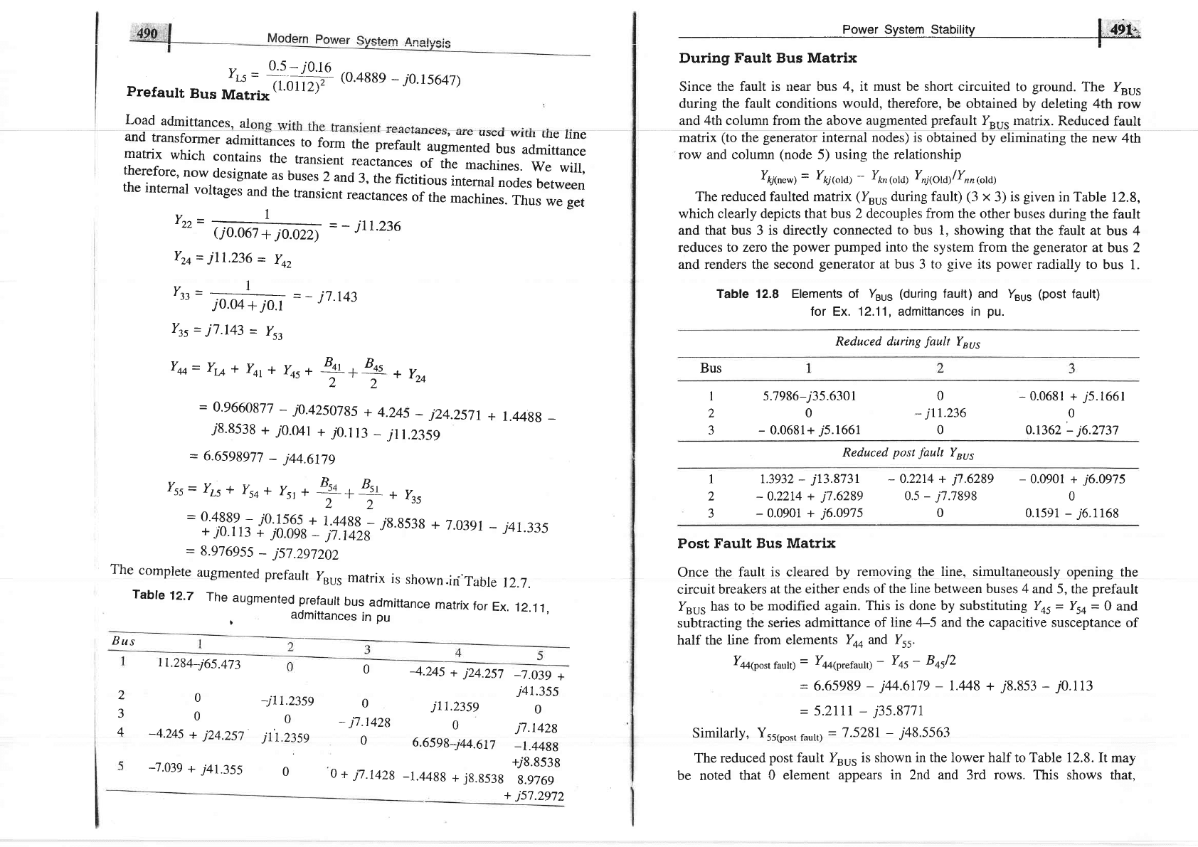
The reduced faulted matrix
()'eus
during
fault)
(3
x
3) is
given
in Table
I2.8,
which clearly depicts that bus 2
decouples from
the other
buses during the
fault
and that bus 3 is directly connected
to
bus 1, showing that
the fault at
bus 4
reduces
to zero the
power pumped
into the
system from the
generator
at
bus 2
and renders the second
generator
at bus 3 to
-eive
its
power
radially
to bus
1.
Table 12.8 Elements of
Yrus
(during
fault)
and Ysus
(post
fault)
for Ex. 12.11, admittances in
pu.
Reduced during
fault
Yu^
Bus
v
0.5
_
j0.16
prefaulr
"r"
*Trl
rr.off
(0'488e
-
i0'1s647)
Load
admittances,
al
Bo,
Bo,'
))
L
I
2
a
J
s.7986-j35.6301
0
-
0.0681+
75.1661
0
-
jrr.236
0
-
0.0681 +
j5.166l
0
0.1362'-
j6.2737
Reduced
post
Jault
Yurt
I
2
-
J
r.3932
-
jr3.873r
-
0.2214
+
j7.6289
-
0.0901 +
j6.0975
-
0.2214
+
j7.6289
-
0.0901 +
j6.O975
0.s
-
j7.7898
0
0
0.1591
-
j6.1168
Bus
Post
Fault Bus Matrix
Once the
fault
is
cleared
by removing the
line,
simultaneously opening
the
circuit
breakers at the
either ends of the
line between buses 4
and 5, the
prefault
Y"u5
has to
be modified again.
This is done by substituting Yqs
=
Ysq
-
0
and
subtracting
the series admittance
of
line 4-5 and the capacitive
susceptance
of
half the line
from elements
Yoo and Ytt.
Y++lporrfault)
=
Y++(prefault)
-
Yqs- 84512
=
6.65989
-
j44.6179
-
1.448 +
78.853
-
j0.113
=
5.2III
-
j35.8771
Similarly,
Ysr(oo*,
rault)
=
7.528I
-
i48.5563
The reduced
post
fault
Y"u5 is shown in the lower half to Table 12.8. It
may
be noted
that 0
element appears
in 2nd and
3rd
rorvs.
This shows that,
2
3
4
rr.284_j6s.473
0
0
-
j7.1428
0
0
+
j7.1428
4.245
+
j24.257
j11.23s9
0
6.6598_j44.617
-1.4488
+
j8.8538
0 _i1r.23sg
06
-4.245
+
j24.257
jll
.2359
-7.039
+
j41.355
0
-7.039
+
j4r.35s
0
j7.t428
-1.4488
+j8.8538
8.9769
+
j57.2972
{92
|
Modern
power
System
Anatysis
-L..^:^^lr-. rr- -
lrrryr'ruarry'
tlle generarors
I
an0
Z
are
not
Interconnected
when
line
4-5
is
removed.
During
Fault
Power
Angle
Equation
Prz=
0
P,3=
Re
[YrrEr,El*
*
El*
\F(];
since
yy=
0
=
E{2
Gn
+
lEil
lEil
lrr,l
cos
(6zr
_
Lzt)
=
(1.071)2
(0.
1362)
+
I x
1.071x
5.1665
cos
(d3
_
90.755")
P"3
=
0.1561
+
5.531
sin
(h
-
0.755)
Postfault
Power
Angle
Equations
p"z=
lE/P
G22 +
lElt
lEll
ly2Ll
cos
(dr,
_
0zr)
=
1.0962
x
0.5005
+
I
x
1.096 x
7.6321
cos
({
-
9I.662")
=
0.6012
+
8.365
sin
(d,
_
I.662)
p,3
=
tE{
2q3
+
Ell
tElt
t\l
cos
(
6r,
_
0rr)
-
7.0712
x
0.1591
+
1
x
1.07r
x
6.09g
cos
(dr
-
90.g466")
=
0.1823
+
6.5282
sin
(d,
_
0.9466")
Swing
Equations-During
Fault
Power
System
Stanitity
I
491,1
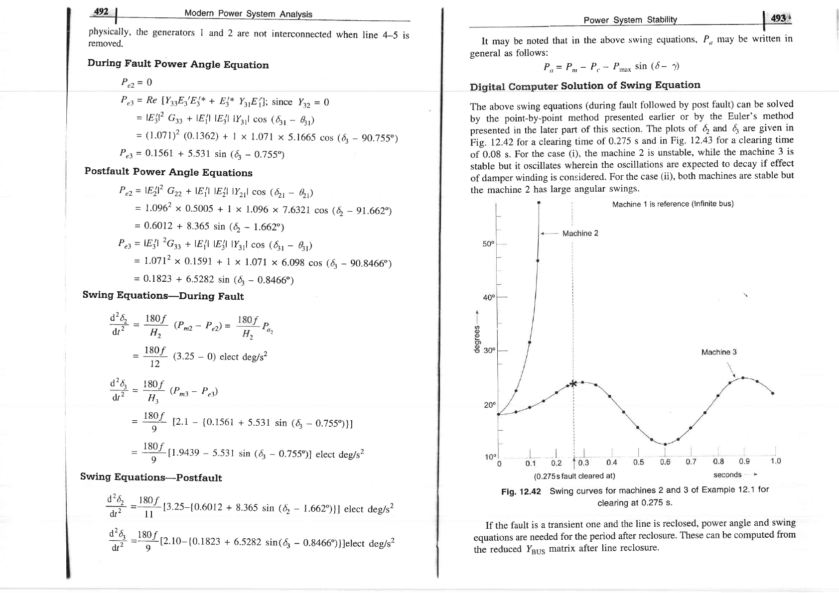
It
rnay be
noted
that
in
the
above
swing
equations,
P,, ntay be
written
in
general as follows:
Pn=
Pr,
-
Pr.
-
P,r,n*
sin
(6-
7)
Solution
of
Swing
Equation
The
above
swing
equations
(during
fault
followed
by
post fault) can
be
solved
by
the
poinrby-point
method
presented
earlier
or
by the
Euler's
method
presented
in
the
later
part
of
this
section.
The
plots
of
E
and
4
are
given in
Fig.
12.42
for
a clearing
time
of 0.21
5 s
and
in
Fig.
12.43
for a clearing
time
of
0.08
s.
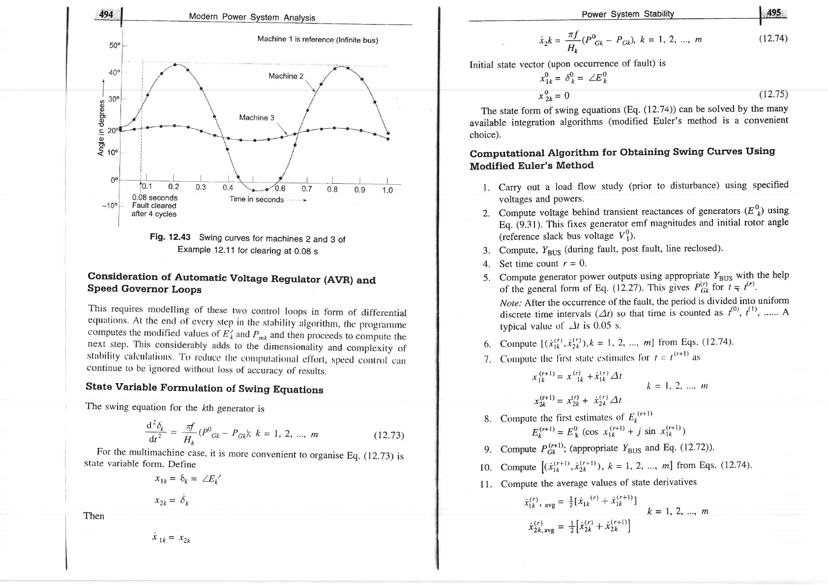
For
the
case
(i),
the
machine
2 is
unstable,
while the
machine
3 is
stable
but
it
oscillates
wherein
the
oscillations
are expected
to decay
if
effect
of
damper
winding
is
considered.
For
the
case
(ii),
both
machines
are
stable
but
the
machine
2
has
large
angular
swings.
(0.275s fault cleared
at)
F\g.12.42
Swing
curves
for
machines
2
and 3 of
Example
12.1
for
clearing
at 0.275
s.
If the
fault
is
a transient
one
and
the
line
is
reclosed,
power
angle
and
swing
equations
are
needed
for
the
period after
reclosure.
These
can
be computed
from
the
reduced
Ysus
matrix
after
line reclosure.
#=ff
(P^z-P,z)=
=
t:9/
e.2s
-
o)
elecr
deg/sz
12
d,q
_
180
f
a'r=
k
(Pn-P"t)
=
t*:/
e.r
-
{0.1s61
+
5.531
sin
(6t
-0.7ss)}l
9
=
Y
l.g43g
-
5.531
sin
(d,
-
0.755")l
elect
d,eg/sz
Swing
Equations-Postfault
#={f
p.2s-10.60r
z +
8.365
sin
(d)
-
t.662")}J
erect
deg/s2
dtd,
180
f
-*
=*12.10-{0.1823
+
6.5282
sin(d3
_
0.g466.)}lelect
deg/sz
dt'
9
Machine
1 is
reference
(lnfinite
bus)
494
|
Modern
power
System
Analysis
500
Machine
1
is reference
(lnfinite
bus)
Machine
2
illtl
_L__
I
_
|
_
0.8
0.9
1.0
Fault
cleared
after
4
cycles
Fig.
12.43
Swing
curves
for
machines
2
and
3
of
Example
12.11
for
clearing
at
0.0g
s
Gonsideration
of
Automatic
voltage
Regulator
(AVR)
and
Speed
Governor
Loops
state
variable
Formulation
of
swing
Equations
The
swing
equation
for
the
hh generator
is
Power
System
Stabilitv
l,,4PFr
.
i*=
#(P"or-
Pco),
k
=
1,2, ...,
m
r7.2
Initial
state
vector
(upon
occurrence
of
fault)
is
xoLk=
fr=
lEot
(t2.74)
(Eo*)
using
rotor
angle
100
at)
c)
o
L
q,
o)
!
o
(t
c
x"zk=
0
The
state
form
of swing
equations
(Eq.
(12.74))
can be
solved
by the
many
available
integration
algorithms
(modified
Euler's
method
is
a convenient
choice).
Computational
Algorithm
for Obtaining
Swing
Currzes
Using
Modified
Euler's
Method
l. Carry
out
a
load
flow
studY
voltages
and
powers.
(prior
to
disturbance)
using
specified
2.
Compute
voltage
behind
transient
reactances
of
generators
Eq.
(9.31).
This
fixes
generator.
emf
magnitudes
and
initial
lreference
slack
bus
voltag"
Y?).
Compute,
Ysu5
(during
fault,
post
fault,
line reclosed).
Set
time
count
r
=
0.
Compute
generator
power
outputs
using
appropriatg
ts"us
with
the
help
of the
geniral
form
of Eq.
(12.27).
This
givet Pg},for
/
1
/').
Note:
After
the
occurrence
of
the fault,
the
period
is
divided
into
uniform
discrete
time
intervals
(At)
so
that
time
is counted
as /(0), t(l),
......
A
typical
value
ol'
lt is
0.05
s.
a
J.
4.
5.
6.
Compute
t(i[;'},i\7'
),k
7.
Corttputc
thc
I'ilsl
stutc
--
1,2,
...,
ml
fiom
Eqs.
(12.74).
cstirrtirlc's
liu'
t
=
,{t+l)
'prr
(r2.73)
For
the
multimachine
case,
it
is
more
convenient
to
organise
Eq.
(12.73)
is
state
variable
form.
Define
xrk=
6r=
lE*'
xz*=
6t
i
t*=
xzt
+
=
+(p'oo-
p");
k
-
r,2,
...,
ffi
dt'
Hk'
u
,[,0*r,
=
,tlo
+i[,0)
at
I
=
|
.2.
....
rrt
,ff')
-
*V)
+ *$'o)
At
8.
Cortrpute
the
first
estimates
of
E^('+t)
BQ+D
=
E?
lcos
x,(i*r)+
7
sin
*\lf'))
g.
Compute
P8;');
(appropriate Y"u5
and
Eq.
(12.72))'
10.
compute
[t;{in'),it:o*t'),
k
=
r,2,
...,
mf
fromEqs.
(12.74).
1
1.
Compute
the
average
values
of
state
derivatives
i[i,)
,
urr= ][iu,cl
+;l[*t)]
k=1,2,...,ffi
iL'),*,
=
*I*\:|
+
,tt'i"
l
Then
1't A
LL.
Lompute
tne
lrnal
state
estimates
for
|
=
t\r+t)-
*;Iu"
=
*([)
+
ill)
uus,
at
,&*r)
-
,([l
+
if).^,rat
k
=
7'2'
"''
frt
Compute
the
final
estimate
for
Eo
at
t
=
r('*l)
using
BQ+t)
=
l4llcos
xf;+r)
+
7
sin
*f1r)
14.
Print (",9*t),
*;:o*D
);
k
=
I,2,
...,
m
15.
Test
for
time
limit
(time
for
which
swing
curve
is
to
be plotted),
i.e.,
checkif
r>
rnnur.
If
not,
r-
r+
r
and
repeat
fromstep5
above.
Otherwise
print
results
and
stop.
The
swing
curves
of
all
the
machines
are plotted.
If
the
rotor
angle
of
a
machine
(or
a
group
of
machines)
with
r"rp".t
to
other
machines
increases
without
bound,
such
a
machine
(or
grouf
of
machines)
is
unstable
and
eventually
falls
out
of
step.
The
computational
algorithm
given
above
can
be
easily
modified
to
include
simulation
of
voltage
regulator,
field
excitation
response,
saturation
of
flux
paths
and
governor
action
Stability
Study
of
Large
Systems
To
limit
the
computer
memory
and
the
time
requirements
and
for
the
sake
of
computational
efficiency,
a
large
multi-machine
system
is
divided
into
a
study
subsystem
and
an
external
system.
The
study
subsystem
is
modelled
in
detail
whereas
approximate
modelling
is
carried
out
for
the
external
subsystem.
The
total
study
is
rendered
by
ihe
modern
technique
of
dynamic
equivalencing.
In
the
external
subsysteln,
nutnber
<lf
rnachines
is
drastically
recluced
using
various
methods-coherency
based
rnethods
being
most
popurar
and
widely
used
by
vanous
power
utilities
in
the
world.
I2.T7
SOME
FACTORS
AFFECTING
TRANSIENT
STABILITY
We
have
seen
in
this
chapter
that
the
two-machine
system
can
be
equivalently
reduced
to
a
single
machine
connected
to
infinite
bus
bar.
The
qualitative
conclusions
regarding
system
stability
drawn
from
a
two-machine
or
an
equivalent
one-machine
infinite
bus
system
can
be
easily
extended
to
a
multimachine
system.
In
the
last
article
we
have
studied
ihe
algorithm
for
determining
the
stability
of a
multimachrne
system.
It
has
been
seen
that
transient
stability
is greatly
affected
by
the
type
and
location
of
a fault,
so
that
a
power
system
analyst
must
at
the
very
outset
of
a
stability
study
decide
on
these
two
factors.
In
ou,
"*u-ples
we
have
selected
a
3-phase
fault
which
is
generally
more
severe
from
point
of
view
of power
transfer'
Given
the
type
of
fault
and
its
location
let
us
now
consider
other
Power
System
Stabitity
|
491;,,
factors which
affect transient stability
and
therefrom
draw
th" .on"llsions,
regarding
methods
of
improving
the transient
stability
lirnit
of a system
and
making
it as close
to
the
steady
state limit
as
possible.
For the case
of one machine
connected
to infinite
bus,
it is easily
seen from
the
angle through which
it
swings in a
given
time interval
offering
thereby a
method of improving
stability
but this cannot
be
employed
in
practice
because
of economic reasons
and for
the reason of
slowing
down
the response
of
the
speed
governor
loop
(which
can even
become
oscillatory)
apart
from
an
excessive
rotor
weight.
With
reference
to Fig. 12.30, it
is easily
seen that for
a
given
clearing
angle,
the accelerating
area decreases
but the
decelerating
area
increases
as
the
maximum
power
limit of the
various power
angle
curves
is raised,
thereby
adding to the transient
stability limit
of the
system.
The
maximum
steady power
of a system can be increased
by raising
the voltage profile
of the system
and
by reducing the transfer reactance.
These
conclusions
along
with
the various
transient
stability cases
studied, suggest
the
following
method
of
improving
the
transient
stability limit of
a
power
system.
1. Increase of
system voltages,
use of
AVR.
2.
Use of high speed
excitation
systems.
3. Reduction in
system transf-er
reactance.
4.
Use
of
high
speed reclosing
breakers
(see
Fig. 12.32).
Mo&rn
tendency
is to
employ single-pole
operation
of reclosing
circuit
breakers.
When a fault
takes
place
on a system,
the voltages
at
all buses
are
reduced.
At
generator
terminals,
these
are
sensed
by the automatic
voltage
regulators
which
help
restore
generator
terminal voltages
by acting
within
the
excitation
system.
Modern exciter
systems having
solid
state
controls quickly
respond
to
bus
voltage reduction
and can
achieve
from one-half
to one
and
one-h'alf
cycles
(l/2-l])
gain
in
critical clearing
times
fbr three-phase
taults
on the
HT bus
of the
generator
transformer.
Reducing
transfer
reactance
is another
important
practical
method
of
increasing
stability limit. Incidentally
this
also raises
system
voltage
profile.
The reactance
of a transmission
line
can
be decreased
(i)
by reducing
the
conductor
spacing, and
(ii)
by increasing
conductor
diameter
(see
Eq.
(2.37)).
Usually, however,
the conductor
spacing
is controlled
by
other features
such
as
lightning
protection
and minimum
clearance
to
prevent
the
arc
from
one phase
moving
to another
phase.
The
conductor
diameter
can
be increased
by using
material of low
conductivity
or by hollow
cores.
However,
norrnally,
the
conductor
configuration is
fixed
by economic
considerations
quite
apart
from
stability. The use
of bundled conductors
is,
of course,
an
effective
means of
reducing
series reactance.
Compensation for line
reactance
by series
capacitors
is an
effective
and
economical method
of increasing
stability
limit
specially
for transmission
'4lI
I
Modern
power
System
Analysis
distances
of
more
than
350
km.
The
ciegree
of
series
compensation,
however,
accentuates
the
problems
of
protective
relaying,
normal
voltage
profiles,
and
overvoltages
drrring
line-to-ground
faults.
Series
cornpensation
becomes
more
effective
and
economical
if
part
of
it
is
of
compensation
upon
the
occurrence
c
S
witehed
series
eapaeitors
simultaneot
and
raise
the
transient
stability
limit
tc
limit.
Switching
shunt
capaciiors
on
ol
stability
limits
(see
Example
12.2)
but
the
MVA
rating
of
shunt
capacitors
required
is
three
to
six
times
the
rating
of
switched
series
capacitors
for
the
same
increase
in
stability
limit.
Thus
series
capacitors
are
preferred
unless
shunt
elements
are
required
for
olher
pu{poses,
siy,
control
of
voltage
profile.
Increasing
the
number
of parallel
lines
between
transmission
points
is quite
often
used
to reduce
transfer
reactance.
It
adds
at
the
same
time
to reliability
of
the
transmission
system.
Aclditional
line
circuits
are
not
likely
to prove
economical
unit
I
aftet
all
feasible
improvements
have
been
carried
out
in
the
first
two
circuits.
As
the
majority
of
faults
are
transient
rn
nature,
rapid
switching
and
isolation
of
unhealthy
lines
followed
by
reclosing
has
been
shown
earliei
to
be
a great
help
in
improving
the
stability
marginr.
ih.
modern
circuit
breaker
technology
has
now
made
it possible
fbr
line
clearing
to
be
done
as
fast
as
in
two
cycles.
Further,
a
great
majority
of
transient
faults
a'e
line-to-ground
in
nature.
It
is
natural
that
methods
have
been
developed
for
selective
single
pole
opening
and
reclosing
which
further
aid
the
stability
limits.
With
,"f"r".,""
to
Fi;.
lz.r7,
if
a
transient
LG
fault
is
assumed
to
occur
on
the generator
bus,
it
is
immedi
ately
::.1,:l_.,
ol,lnt
the
fault
there
will
now
be
a
definite
amount
of
power
rransfer,
nd dr++^s^^L L----
ab
uurereni
rrom
zero
power
transfer
for
the
case
of
a
three-phase
fault.
Also
when
the
circuit
breaker
pole
corresponding
to
the
faulty
line
is
opened,
the
other
two
lines
(healthy
ones)
remain
intact
so
that
considlrable
power
transfer
continues
to
take
place
via
these
lines
in
comparison
to
the
case
of
three-pole
switching
when
the power
transfer
on
fault
clearing
will
be
reduced
to
zero.
It
is,
therelbre,
easy
to
see
why
the
single
pole
swiiching
and
reclosing
aids
in
stability
problem
and
is
widely
adopted.
These
facts
arelilustrated
by
means
of
Example
12'12.
Even
when
the
stability
margins
are
sufficient,
single
pole
switching
is
adopted
to prevent
large
swings
and
consequent
vortage
dips.
Single
pole
switching
and
reclosing
is,
of
course,
expensiu.
in
t..*s
of
relaying
and
introduces
the
as.socjatec!
problerns
of
overvoltages
caused
by
single
pole
opening
owing
to
line
capacitances.
Methods
are
available
to
nullify
these
capacitive
coupling
effects.
Recent
Trends
Recent
trends
in
design
of large
alternators
tend
towards
lower
short
circuit
ratio
(scR =
r/x),
which
is
achieved
by
reducing
machine
air gap
with
consequent
savings
in
machine
mmf,
size,
weight
and
cost.
Reduction
in
the
I
I :.-^Ir
.
I.1.':/tlltt, i::
stze
of
rotor reduces
inertia
constant,
Iowering
thereby
the
stability
margin.
The
loss
in
stability
margin
is
made
up
by such
features
as
lower
reactance
lines,
faster
circuit breakers
and faster
cxcitation
systenrs
as
tliscussetl
alreacly,
and
a faster
system
valving
to be
discussed
later
in
this
article.
A
stage
has now
been
reached
in technology
whereby
the
methods
of
irnprovinE=stability;
discussetl
above,
have
been
pushed
to
their
limits,
e.g.,
clearing
times
of
circuit
breakers
have
been
brought
down
to virnrally
irreducible
values
of the
order
of two
cycles.
With
the trend
to
reduce
machine
inertias
there
is
a constant
need
to
determine
availability,
feasibility
and
applicability
of
new
methods
for
maintaining
and/or
improving
system
stability.
A brief
account
of
some
of
the recent
methods
of
maintaining
stability
is given
below:
HVDC
Links
Increased
use of
HVDC
links
ernploying
thyristors
would
alleviate
stability
problems.
A dc
link
is
asynchronous,
i.e.,
the
two
ac
system
at
either
end
do
not
have
to be controlled
in
phase
or even
be
at
exactly
the
same
frequency
as
they
do
for an
ac
link,
and
the
power
transmitted
can
be
readily
controlled.
There
is no
risk
of
a fault
in
one
system
causing
loss
of stability
in the
other
system.
Breakingr
Resistors
For
improving
stability
where
clearing
is delayed
or
a
large
tn)a
i,
suddenly
lost,
a
resistive
load
called
a
breaking
resistor
is
connected
at
or near
the
generator
bus.
This load
compensates
for at
least
sonre
of
the
reduction
of
load
on the generators
and
so
reduces
the
acceleration.
During
a
f-ault,
the resistors
are
applied
to the
terminals
of
the generators
through
circuit
breakers
by
means
of
an
elaborate
control
scheme.
The
control
scheme
determines
the
amount
of
resistance
to be
applied
and
its
duration.
The
breaking
resistors
remain
on
for
a
matter
of
cycles
b<lth
during
fault
clearing
and
after
system
voltage
is
restored.
Short
Circuit
Current
Limiters
These
are generally
used to
limit
the
short
circuit
duty
of
distribution
lines.
These
may
also be
used
in
long
transmission
lines
to
modify
favourably
the
transfer
impedance
during
fault
conditions
so
that
the voltage
profile
of
the
system
is somewhat
improved,
thereby
raising
the
system
load
level
durins
the
fault.
Turbine
Fast
Valuing
or Bypass
Valuing
The
two
methods
just
discussed
above
are
an
attempt
at
replacing
the
sysrem
load
so as
to increase
the
electrical
output
of
the
generator
during
fault
conditions.
Another
recent
method
of improving
the
stability
of
a
unit
is to
decrease
the
mechanical
input power
to
the
turbine.
This
can
be
accornplished
by
rneans
of fast
valving.
where
the
differenee
between
mechanical
input
and
reduced
electrical
output
of a
generator
under
a fault,
as sensed
by
a control
scheme,
initiates
the
closing
of
a
turbine
valve
to reduce
the
power
input.
Briefly,
during
a
fast
valving
operation,
the
interceptor
valves
are rapidly
shut
(in
0.1 to
0.2 sec)
and
immediately
reopened.
This
procedure
increases
the
critical
switching
time
lons
enoush
stable
for faults
with
stuck-breaker
clearing
times.
The
scheme
has
been
put
to
use in
some
stations
in
the
USA.
FUII
Load
Rejection
Technique
Fast
valving
combined
with
high-speed
clearing
time
will
suffice
to maintain
stability
in
most
of
the
cases.
However,
there
are still
situations
where
stabilitv
is difficult
to
maintain.
In such
cases,
the
normal
procedure
is
to
automatically
trip
the unit
off the
line.
This,
however,
causes
several
hours
of delay
before
the
unit
can
be
put
back
into
operation.
The
loss
of
a major
unit
for
this
length
of tirne
can
seriously
jeopardize
the
remaining
system.
To
remedy
these
situations,
a
full
load
rejection
scheme
could
be utilized
after
the
unit
is
separated
from
the
system.
To
do this,
the
unit has
to be
equipped
with
a large
steam
bypass
system.
After
the
system
has
recovered
from
the
shock
caused
by the
fault,
the
unit
could
be
resynchronized
and
reloaded.
The
main
disadvantage
of
this
method
is
the
extra
cost
of
a large
bypass
system.
The
systetn
shown
in Fig.
12.44
is loaded
to
I
pu.
Calculate
the
swing
curve
and
ascertain
systern
stability
for:
(i)
LG fault
three pole
switching
followecl
hy
reclosure.
linc
louncl
healthy.
(ii)
LG
fault
single pole
switching
fbllowed
by reclosure,
line
found
healthy.
Switching
occurs
at
3.75
cycles
(0.075
sec)
and
reclosure
occllrs
at 16.25
cycles
(0.325
sec).
All values
shown
in the
figure
are
in
pu.
-
l.r.l=.,
,?_
Xr=
0.1
r---
-
--l
JI
-,t
0.15
|
7l
I
0'1
p
0'3
0.1
|
L --z
-rfd]-ui-r
i-dT
L_r6TT\_ I
(b)
Negative
sequence
network
Fig.
12.45
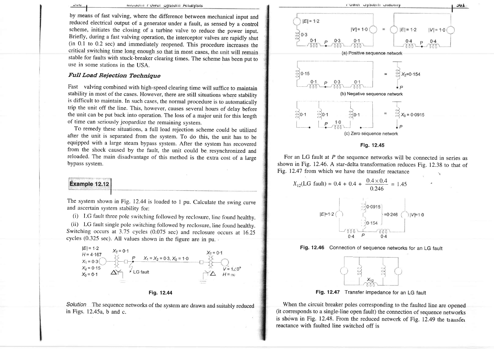
For
an LG fault
at P the
sequence
networks
will
be
connected
in
series-as
shown
in Fig. 12.46.
A star-delta
transformation
reduces
Fig.
12.38
to
that
of
Fig. 12.47
from which
we
have the
transfer
reactance
Xr2(LG
faulQ
=
0.4 +
0.4 +
nOII''O
=
1.45
0.246
I
I
.-t.
lEl=1'2
(
)
I
r-rd
60
0'4
Fig.12.46
Connection
of
sequence
networks
for
an LG
fault
f-
(,r
Fig.12.47
Transfer
impedance
for
an
LG
fault
When
the circuit
breaker
poles
corresponding
to
the
faulted
line
are
opened
(it
corresponds
to a single-line
open fault)
the
connection
of
sequence
networks
is shciwn in Fig.
12.48. From
the reduced
network
of Fig.
12.49 the
rransfer
reactance
with faulted
line
switched
off is
t
T
-t
I
-t-
;.i)l_C
ao
''
l]o
t
go
''
|
=
l
xo
=
0.0e15
| |
p
1'o
| | I
L----.-'
I
i-rT60
t;,'r";*u1n""
networl
P
o'4
H
=
4.167
-'.
Xr
=
o
3Oj
?*f
-h'Ir-!.&-f!
Xt=0'15
'L
(/
xo=
o.t
AY-l
Fig.
12.44
Solution
The
sequence
networks
of the
system
are drawn
and
suitably
reduced
in Figs.
I2.45a,
b
and c.
I l'
Xn
'lr
t
I
r/-ftrf\r
___J
Y.^
(fettlterl
line nnen\
-
0 A t A A1 r
(l
A - 1 ..
-^ll
\-*---
-
v.-
|
v.aL
-r
V..+
_
L../-L
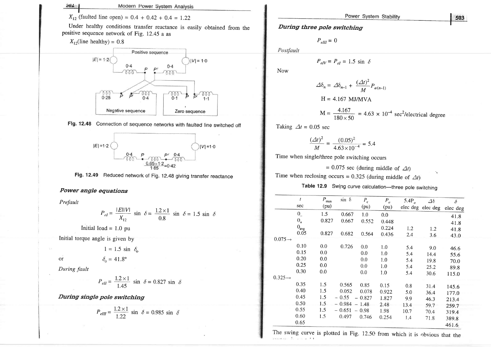
Under healthy
conditions
transfer
reactance
is
easily
obtained
from
the
positive
sequence
network
of
Fig.
12.45
a
as
Xrr(line
healthy)
=
0.8
Zero
sequence
Flg.12-48
Connection
of
sequence
networks
with
faulted
line
switched
off
lEl=1'z
lvl
=1'o
Fig.
12.49
Reduced
network
of
Fig.
12.49
giving
transfer
reactance
I
.o.ro
Pettt
=
0
Now
PrN=
Pd
=
1.5
sin
d
46,-
A6n-,
+
@LP^,-
,,
M
'a(n-l)
H
=
4.167
MJA{VA
o'1
P
1,1=
JU-
-
4.63
x
10a
sec2lelectrical
degree
180
x
50
Taking
At
=
0.05
sec
(at)'
5.4
4.63xI0-4
Time
when
single/three
pole
switching
occurs
=
0.075
sec
(during
middle
of
At)
.,
Time
when
reclosing
occurs
=
0.325
(during
middle
of
at)
Table
12.9
swing
curye
calculation-three
pole
switching
Power
angle
eguations
PreJault
p,=
rE
vr
sin
d=
X,,
Initial
load
=
1.0
pu
Initial
torque
angle
is
given
by
or
During
fault
1
=
1.5
sin
5o
6o
=
47.8"
7.2x1
-
SlIl
d= l.)
stn b
0.8
L
sec
P,u,o
P,,
(pu)
)
1.5
0.667
0.827
0.667
0.827
0.682
0.0
0.726
0.0
0.0
0.0
0.0
1.5
0.565
1.5
0.052
1.5
-
0.55
1.5
-
0.984
1.5
-
0.651
r.5
0.497
.5.4P,,
ifi
elec
deg
elec
deg
6P"
(pu)
6
elec
deg
0.075---+
0.10
0.15
0.20
o.25
0.30
0.325--+
0.3s
0.40
0.45
0.50
0.s5
0.60
0.65
r.0
0.0
0.552
0.448
0.224
0.564
0.436
0.0
1.0
0.0
1.0
0.0
1.0
0.0
1.0
0.0
1.0
0.85
0.15
0.078
0.922
-
0.827
r.827
-
r.48
2.48
-
0.98
1.98
0.146
0.254
41.8
41.8
1.2
41.8
3.6
43.0
9.0
46.6
r4.4
55.6
19.8
70.0
2s.2
89.8
30.6
I
15.0
31.4
36.4
46.3
59.7
10.4
71.8
0
o*
ouu,
0.05
1.2
NA
F
l.Zxl
'",,
=
lff
sin
d
=
0.827
sin
I)uring
single
pole
switching
Perrr
=
+#
sin
d
=
0.985
sin
5.4
5.4
5.4
5.4
5.4
0.8
5.0
9.9
13.4
10.7
t.4
r45.6
177.O
2r3.4
259.7
3r9.4
389.8
461.6
Negative
sequence
P
P/
o:4
The
swing
curve
is
plotted
in
Fig.
12.50
from
which
it
is obvious
that
rhe