Leroy C., Rancoita P.-G. Principles Of Radiation Interaction In Matter And Detection
Подождите немного. Документ загружается.

January 9, 2009 10:21 World Scientific Book - 9.75in x 6.5in ws-bo ok975x65˙n˙2nd˙Ed
480 Principles of Radiation Interaction in Matter and Detection
carriers, one finds:
Q = Q
e
+ Q
h
(6.86)
= −Q
0
Z
t
t
r,e
0
exp (−t/τ
e
)
µ
e
E
d
dt
−Q
0
Z
t
t
r,h
0
exp (−t/τ
h
)
µ
h
E
d
dt
or
Q = Q
e
+ Q
h
(6.87)
=
Q
0
d
µ
e
E τ
e
·
1 − exp
µ
−
d − x
0
µ
e
E τ
e
¶¸
+
Q
0
d
µ
h
E τ
h
·
1 − exp
µ
−
x
0
µ
h
E τ
h
¶¸
.
Using the simplified notations,
Λ
e
= µ
e
E τ
e
(6.88)
and
Λ
h
= µ
h
E τ
h
, (6.89)
one finds
Q = Q
0
½
Λ
e
d
·
1 − exp
µ
−
d − x
0
Λ
e
¶¸
+
Λ
h
d
·
1 − exp
µ
−
x
0
Λ
h
¶¸¾
, (6.90)
which is the Hecht equation [Hecht (1932)]. Then, the charge collection efficiency,
CCE, is the ratio of the collected charge to the initial charge Q
0
:
CCE =
Q
Q
0
(6.91)
with Q
0
= N
0
q, where N
0
= E/E
ion
is the number of electron-hole pairs created
at the point x
0
by an incident particle of energy E and E
ion
is the energy needed
to create an electron-hole pair, E
ion
= 3.62 eV for silicon. Equation (6.91) can be
applied to determine the CCE of detectors illuminated by α-particles.
The range of α-particle in silicon is 25 µm for α-particle from
241
Am source and
cannot cross the whole depth of the detector which is a few hundreds µm thick
in practice. For a source confined under vacuum, the α-particle incident energy is
∼ 5.45 MeV and Q
0
= (5.45 × 10
6
/3.62)1.6 × 10
−19
C ∼ 0.24 pC.
The CCE depends on Λ
e
, Λ
h
and the point x
0
where the charge has been
created. This point is not accessible experimentally. The location of this point be-
ing random, the width of the peak in the energy spectrum broadens. The relative
broadening is [Iwanczyk, Schnepple and Materson (1992)]:
σ(E)
E
=
2Λ
e
2
Λ
h
2
d
3
(Λ
e
− Λ
h
)
³
e
−d/Λ
e
− e
−d/Λ
h
´
−
1
d
4
h
Λ
e
2
³
e
−d/Λ
e
− 1
´
+ Λ
h
2
³
e
−d/Λ
h
− 1
´i
2
−
Λ
e
3
2d
3
³
e
−2d/Λ
e
− 1
´
−
Λ
h
3
2d
3
³
e
−2d/Λ
h
− 1
´
. (6.92)
January 9, 2009 10:21 World Scientific Book - 9.75in x 6.5in ws-bo ok975x65˙n˙2nd˙Ed
Solid State Detectors 481
The CCE and width improve with the increase of Λ
e
/d and Λ
h
/d. Note that
Λ
e,h
d
=
τ
e,h
µ
e,h
E
f
d
=
τ
e,h
µ
e,h
ρ j
d
,
where
E
f
,
ρ
and
j
=
i/d
are the electric field, the semiconductor resistivity and
the leakage current density, respectively [Abyzov, Davydov, Kutny, Rybka, Row-
land and Smith (1999)]. To optimize the energy resolution, one should maximize
τ
e,h
µ
e,h
ρ j with the constraint, however, that the leakage current, i, contributes to
the noise charge
ENC
p
=
s
iθ
q
,
which has to be minimized [θ is the pulse shaping time of the preamplifier, expression
already used earlier, see Eq. (6.80)].
For minimum ionizing β-particles, which traverse the whole depth of the detec-
tor, calculations similar to those leading to Eq. (6.90) can be done and lead to a
ratio of collected charge Q
coll
to the initial charge Q
0
:
CCE
β
=
Q
coll
Q
0
=
Λ
e
+ Λ
h
d
−
µ
Λ
e
d
2
³
1 − e
−d/Λ
e
´
−
µ
Λ
h
d
2
³
1 − e
−d/Λ
h
´
. (6.93)
In the case of relativistic electrons (selected for instance from β-particles produced
by a
106
Ru source) traversing a silicon detector 300 µm thick, the energy loss is
about 80 keV per 300 µm and Q
0
= (80 × 10
3
/3.62)1.6 × 10
−19
C ∼ 3.5 fC, as seen
before.
6.3 Spectroscopic Characteristics of Standard Planar Detectors
Precise spectroscopy technique is a powerful tool for investigating features and
functionalities of semiconductor detectors [Casse et al. (1999a); Chren et al. (2001);
Houdayer et al. (2002)]. It provides information on the structure and charge col-
lection capabilities of the detectors. The scanning of the diode structure and its
sensitive volume by illuminating the front and back sides with heavy charged par-
ticles (alpha’s and protons) of low energy and well defined range is illustrated in
Fig. 6.18. In the case of α-particles, the pulse height is given by:
V
ph
= η
qE
α
E
ion
C
, (6.94)
where E
α
is the α-particle energy deposited in silicon, q is the electronic charge, E
ion
(= 3.62 eV) is the energy necessary to produce a electron-hole pair and, finally, C
is the detector capacitance. The factor η is the charge collection efficiency. For high
ionizing radiation, such as α-particles, η also reflects possible plasma effects, which
January 9, 2009 10:21 World Scientific Book - 9.75in x 6.5in ws-bo ok975x65˙n˙2nd˙Ed
482 Principles of Radiation Interaction in Matter and Detection
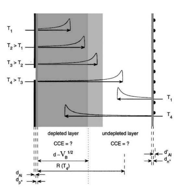
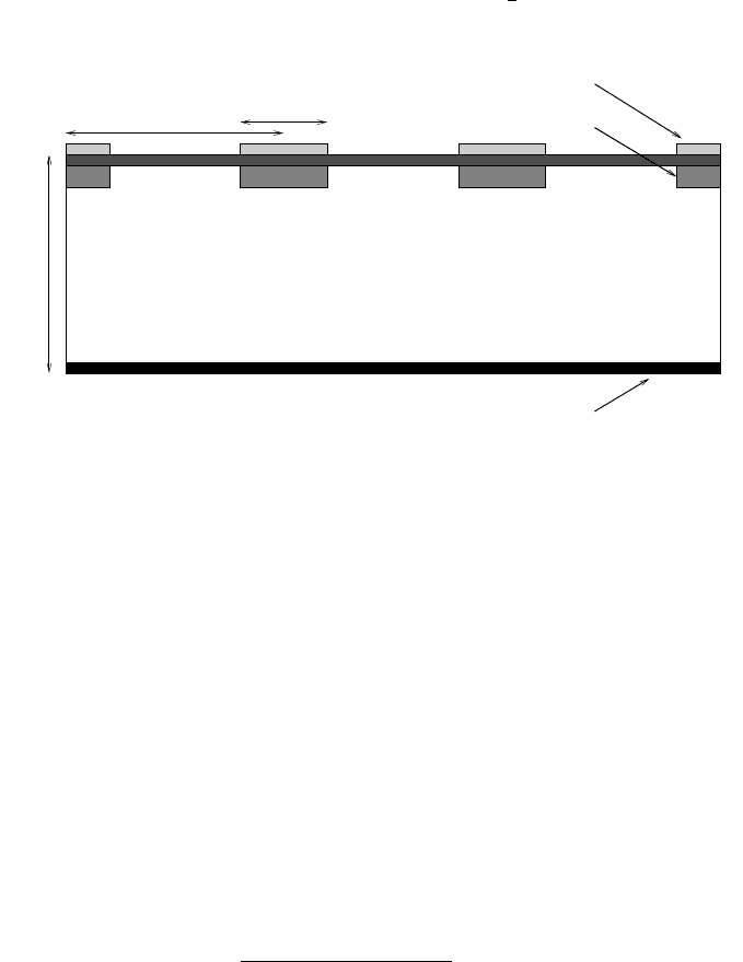
Fig. 6.18 Illustration in the schematic cross-sectional view of a detector of thickness d, of the
method for scanning the detector structure and sensitive volume (from [Leroy and Rancoita (2007)];
see also [Casse et al. (1999a)]). The thicknesses of Al contact metallisation and p
+
layer (front side)
or n
+
layer (back side) are indicated. The shaded area represents the depleted region (detector sen-
sitive volume). The detector response is measured as a function of the applied bias voltage for pro-
tons or alpha particles incident on the front or on the back side at energies T
4
> T
3
> T
2
> T
1
,
corresponding to incoming particle ranges R(T
4
) > R(T
3
) > R(T
2
) > R(T
1
) inside the detec-
tor. Bragg energy-loss distributions inside the detectors are shown for the various incident energies.
affect the collection efficiency. For instance, in Fig. 6.18 it is shown the dependence
of the depth of the depleted (sensitive) layer on the applied bias voltage (V
b
) is
compared with the Bragg curve distribution of charge produced along the path of
the incoming particle.
Pulse-height spectra are obtained by measuring the signal of the diodes with
a standard spectroscopy system. The pulse-height spectra are recorded at various
applied bias voltages.
The variation of the peak p osition with the incoming particle energy and the
applied bias voltage provides precise information on the spatial efficiency of the
charge collection controlled by the electric field configuration inside the diode. This
technique requires the use of a reference detector, a silicon surface barrier detector
(SSBD) which has a thin entrance window, an excellent energy resolution and 100 %
January 9, 2009 10:21 World Scientific Book - 9.75in x 6.5in ws-bo ok975x65˙n˙2nd˙Ed
Solid State Detectors 483
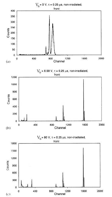
Fig. 6.19 Spectra illustrating the response of a SP detector to alpha particles from Pu, ThC
and ThC’ sources incident on the front side of the diode for various applied reverse bias voltage:
V
b
= 0.0 (a), 8.7 (b) and 80 V (c) (from [Leroy and Rancoita (2007)]; see also [Casse et al.
(1999a)]). The shaping time was τ = 0.25 µs.
charge collection efficiency (CCE). The normalization of the peak position observed
with the diodes under study to that observed with the reference detector is used
to determine the CCE. Typically, the Full-Width at Half-Maximum (FWHM) at
5.486 MeV (
241
Am α-line) for the SSBD is 14 keV, giving a relative energy resolution
of a fraction of the percent for the whole spectroscopy system (including the refe-
rence detector). This very good energy resolution achieved allows the observation
of changes in pulse height resulting from changes in CCE and/or influence of the
electrode structures. From the splitting and shifts of α-peak, one can determine the
January 9, 2009 10:21 World Scientific Book - 9.75in x 6.5in ws-bo ok975x65˙n˙2nd˙Ed
484 Principles of Radiation Interaction in Matter and Detection
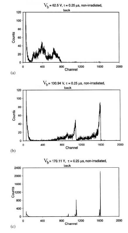
Fig. 6.20 Spectra illustrating the response of a SP detector to alpha particles from Pu, ThC
and ThC’ sources incident on the back side of the diode for applied reverse bias: V
b
= 62.5 (a),
100.9 (b) and 170.1 V (c) (from [Leroy and Rancoita (2007)]; see also [Casse et al. (1999a)]). The
shaping time was τ = 0.25 µs.
thicknesses of metallic electrodes and implanted layers. The capability to measure
shifts at the level of a keV is equivalent to measuring layer thicknesses of about ten
nanometers.
Some of the spectra illustrating the response of a Standard Planar (SP) detector
to α-particles impinging on the front (back) side of the diode are shown in Fig. 6.19
(Fig. 6.20) for different values of applied reverse bias (V
b
= 0.0, 8.7, 80 V), with a
shaping time τ = 0.25 µs.
The understanding of these peaks behavior is presented in [Casse et al.

January 9, 2009 10:21 World Scientific Book - 9.75in x 6.5in ws-bo ok975x65˙n˙2nd˙Ed
Solid State Detectors 485
(1999a)]. The sensitivity of the spectroscopic method for SP detectors is illustrated
in Fig. 6.21. The response of the reference SBBD detector [Fig. 6.21 (a)] is compared
with the responses of a SP detector illuminated from the front side [Fig. 6.21 (b)]
and from the back side [Fig. 6.21 (c)]. From the splitting and shifts of the α-peak,
one can determine the thicknesses of metallic electro des and of implanted layers as
well.
6.3.1 Energy Resolution of Standard Planar Detectors
Semiconductor detectors have very good energy resolution. There are several con-
tributions to the resolution such as statistics of electron-hole formation, detector
and readout noises. If one considers only the contribution of electron-hole formation
statistics, the energy resolution of a planar silicon detector is, in standard notation:
σ
R
= 2.36 × σ(E), (6.95)
where σ(E) is the standard deviation in the amount of energy deposited in the
detector by an incident monoenergetic particle. If N
e−h
is the average number of
electron-hole pairs produced by the incident particle in the material, σ
R
can be
written as:
σ
R
= 2.36 × E
ion
p
N
e−h
, (6.96)
where E
ion
(= 3.62 eV) is the average energy to create a electron-hole pair in sili-
con. If E (expressed in eV) is the energy of the incident particle,
N
e−h
=
E
E
ion
and one finds
σ
R
= 2.36 ×
p
EE
ion
. (6.97)
For an incident particle of 5 MeV on silicon, σ
R
= 10 keV. For a 140 keV Compton-
photon emitted by a
99m
Tc source, σ
R
= 1.7 keV.
The other contributions to the energy resolution depend on the particular read-
out electronic chain used for the measurements. For instance, for an α-particle
emitted by an
241
Am source, E = 5.486 MeV, the application of Eq. (6.97) gives
σ
R
= 10.5 keV, i.e., a relative energy resolution of 0.2%. However, the measure-
ment performed with a standard spectroscopy system composed of a charge-sensitive
preamplifier, linear shaping amplifier and multichannel analyzer rather gives for the
same alpha line: σ
R
= 14 keV or a relative energy resolution of 0.3%. The difference
between the measurement and the value found through Eq. (6.97) is explained by
the readout chain noise not accounted in the equation.
January 9, 2009 10:21 World Scientific Book - 9.75in x 6.5in ws-bo ok975x65˙n˙2nd˙Ed
486 Principles of Radiation Interaction in Matter and Detection
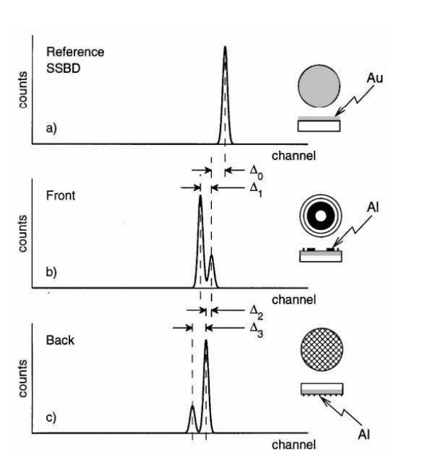
Fig. 6.21 Illustration of the sensitivity of the spectroscopic method (from [Leroy and Rancoita
(2007)]; see also [Casse et al. (1999a)]). The response of a reference silicon surface barrier detector
(SSBD) (a) is compared to the response of a SP detector illuminated (b) on the front side and
(c) on the back side. Shifts among peaks and their splitting are caused by different losses of
particles entering through non-sensitive layers on the detector surface. ∆
0
: the difference of the
thicknesses of layers due to different losses in the Au reference detector electrode and p
+
layer of
the measured detector (' 20 keV), ∆
1
: thickness of front Al electrode (' 86 keV), ∆
2
: backside
n
+
layer thickness compared to p
+
(' 33 keV), ∆
3
: backside Al grid thickness (' 122 keV). The
thicknesses are expressed in terms of the corresponding energy-losses.
6.4 Microstrip Detectors
The division of the p-side of a silicon diode into an array of parallel narrow strips
provides a position sensitive detector. The carriers (electrons and holes) created
around the incident particle track are basically confined in a tube of ≈ 1 µm of
diameter around the track. The charge created drifts under the electric field. In a
n-type silicon with p
+
-strips, the holes will move to the diode strips and electrons
to the backplane (or ground plane), see Fig. 6.22. For instance, for a 300 µm thick
detector under a bias voltage of 150 Volts, the electric field is 5.0 kV/cm and the drift
velocities are 6.75×10
6
cm/s and 2.25×10
6
cm/s for electron and hole, respectively.

January 9, 2009 10:21 World Scientific Book - 9.75in x 6.5in ws-bo ok975x65˙n˙2nd˙Ed
Solid State Detectors 487
The electrons created closer to the diode strips will take more time to migrate to
the backplane. The same is true for the holes created closer to the backplane which
will take more time to reach the junction side. During the drift time, the narrow
tube of charge carriers broadens as a result of multiple collisions and the carrier
distribution obeys a Gaussian law:
dN
N
=
1
√
4πD
i
t
exp
µ
−
x
2
4D
i
t
, (6.98)
where dN/N is the fraction of charge carriers in the element dx at a distance x from
the origin of charge location after a time t. D
i
(i = e, h) is the diffusion coefficient
for the i-carrier and is given by Eq. (6.62).
At room temperature, Eq. (6.62) gives D
e
= 34 .9 cm
2
/s and D
h
= 11 .6 cm
2
/s
using µ
e
= 1350 cm
2
V
−1
s
−1
and µ
h
= 450 cm
2
V
−1
s
−1
, respectively. The root mean
square in Eq. (6.98), i.e.,
√
2D
i
is the same for electrons and holes since the drift
time t ∼ 1/µ. The diffusion of charge carriers obviously affects the spatial resolution
of the microstrip detectors.
Statistical fluctuations of the energy loss is another effect to be considered with
that respect. The statistical nature of the ionization process on the passage of a fast
charged particle through matter results in large fluctuations of energy losses in the
silicon detector, which are usually very thin compared to the particle range. One
has already seen in Sect. 2.1.2 that these fluctuations can be calculated using Lan-
dau and Vavilov distributions (Vavilov provides a more accurate solution by in-
troducing the kinematical limit on the maximum transferable energy in a single
collision). Binding of electrons in silicon atoms broadens the theoretical Landau
distribution of the energy-loss measured in the silicon detector. The correct distri-
bution of energy loss is obtained from the convolution of a Landau distribution and
a Gaussian corresponding to a correction for the binding energies of electrons in
silicon and taking into account the electronics noise [Shulek et al. (1966); Hancock,
James, Movchet, Rancoita and Van Rossum (1983, 1984); Caccia et al. (1987)]. The
production of energetic secondary electrons contributes to the energy loss in silicon,
in addition to the creation of electron–hole pairs. Then, displacement of the charge
distribution is due to secondary electrons ejected with an energy larger than T ,
which is the kinetic energy imparted to the electrons ejected from the collision of
the incoming particle with atomic electrons [Damerell (1984)]. The maximal kinetic
energy which can be transferred from a collision of an incoming particle (not an
electron) of mass m and energy E with an atomic electron of mass m
e
is [Eq. (1.28)
on page 10]:
T
max
= 2m
e
c
2
β
2
γ
2
·
1 +
³
m
e
m
´
2
+ 2γ
m
e
m
¸
−1
=
2m
e
p
2
(m
2
+ m
e
2
+ 2m
e
E/c
2
)
, (6.99)
where the incoming particle momentum is
p = mγβc, with γ =
E
mc
2
and β =
v
c
January 9, 2009 10:21 World Scientific Book - 9.75in x 6.5in ws-bo ok975x65˙n˙2nd˙Ed
488 Principles of Radiation Interaction in Matter and Detection
(v is the incoming particle velocity). In the case of an incoming electron (see
Sect. 2.1.6.1), since the outgoing electron of higher energy is considered to be the
primary electron, the maximum energy transferred is
1
2
of the incoming electron
kinetic energy.
w
p
d
p strip
aluminium strip
n backplane
n−type bulk
+
+
Fig. 6.22 Standard representation of a n-type strip detector; p is the strip pitch, d is the detector
thickness and w is the width of the p
+
implant.
The probability to eject secondary electrons (δ-rays) of kinetic energy higher or
equal to T is decreasing by about 4 orders of magnitude as T increases from 100 eV
to 1 MeV (see Sect. 2.1.2.1). However, these high energy electrons, although their
numb er decreases with increasing energy, have an increasing range in silicon. Each
ejected electron releases an increasing number of secondaries in silicon with the
result [Damerell (1984)] that the mean charge released in silicon increases linearly
with ln(T ).
As seen before, a relativistic electron releases about 80 keV in a silicon thickness
of 300 µm, which corresponds to 22000 electrons released around its track. If in
addition, a δ-ray of 50 keV is produced and drifts perpendicularly to the track, its
range will be about 16 µm in silicon and, therefore, 50 keV/3.62 eV ∼ 13800 addi-
tional electrons will be produced along this ray track and will shift (see [Damerell
(1984)]) the centroid of the charge distribution, assuming the secondary charge is
produced halfway from the track, by an amount ∆ of
∆ =
22000 × 0 + 13800 × 8
22000 + 13800
∼ 3.6 µm. (6.100)
From Eq. (2.38) on page 55 (see also Fig. 10 in [Damerell (1984)]), it is seen that
about 4×10
−4
electrons with an energy greater or equal to 50 keV are ejected per mi-
crometer of track. In the case of a silicon detector 300 µm thick, there is then a 11%
probability of producing a δ-ray which shifts the centroid of the charge distribution
by about 3 µm. The numb er of electron–hole pairs produced in a silicon detector

January 9, 2009 10:21 World Scientific Book - 9.75in x 6.5in ws-bo ok975x65˙n˙2nd˙Ed
Solid State Detectors 489
will increase with its thickness. However, the probability to produce δ-rays with
higher range in silicon will also increase and affect the position resolution. Thinner
the detector is, lower will be the probability that such a δ-ray exists and greater
will be the spatial resolution of the detector; although there is clearly a practical
limit in lowering the thickness of the silicon detector [Manfredi and Ragusa (1985)].
The value of the strip pitch, “p” (see Fig. 6.22), influences largely the design
and performances of the microstrip detectors. Intuitively, one would choose it as
small as possible in order to have a dense array of strips and the signal spread over
several strips. This would allow one to reconstruct the charge distribution and find
the impact point of the incoming particle by calculating the center of gravity of the
charge distributed over the strips. However, to have the signal really shared by sev-
eral strips, one should use pitches of the order of a few µm since measured F W HM
of charge distribution is of the order of 10 µm [Belau et al. (1983)]. This is practically
impossible to achieve. In practice, the readout pitch is 20−25 µm. The charge will
be collected on one strip, the strip number giving the track position. The position
can be measured more precisely for tracks generating signals on two strips. In the
case of tracks of particles traversing the detector in between two consecutive strips,
the position is calculated again by taking the center of gravity of the charge distri-
bution or inferred from the shape of the charge distribution. The precision on the
measurement of the position, when several strips share the charge, depends of the
relative position of the track with respect to the strips involved since the strip closer
to the track will show a larger signal than the strip farther. Then, the precision of
the measurement depends on the noise which is expected to be relatively larger for
the smaller signal. For a readout pitch of 25 µm, the precision of localization is a
few microns.
Most of the time, financial costs, geometrical and mechanical constraints may
lead to a reduction in the number readout channels. It means that the space between
two consecutive active (readout) strips is increased, which means an increase of the
effective pitch value, and, consequently, a decrease of the number of events detected
by two strips. To remedy this problem, diodes are introduced between the readout
strips [England et al. (1981); K¨otz et al. (1985)]. The charges collected on those
intermediate strips are transferred by capacitive coupling to the readout strips. Such
a procedure feeds up the number of events detected on the two readout strips.
More generally, the interplay between the dimension of the pitch, the strip width
and the thickness of the diode determines the operational features of the microstrip
detector as it influences the noise of the electronics readout. As we already did in
this section, it is standard to approximate a silicon microstrip by a planar dio de of
thickness d and width w. Neglecting the built-in voltage V
0
in Eqs. (6.22, 6.24), the
depth, x, of the depleted layer is given as a function of the bias voltage V
b
x =
s
2²V
b
q |N
eff
|
, (6.101)