Leroy C., Rancoita P.-G. Principles Of Radiation Interaction In Matter And Detection
Подождите немного. Документ загружается.


January 9, 2009 10:21 World Scientific Book - 9.75in x 6.5in ws-bo ok975x65˙n˙2nd˙Ed
510 Principles of Radiation Interaction in Matter and Detection
layer-detector interface, in order to reach and penetrate the silicon layer where they
deposit their energy. Charge carriers are then generated in silicon yielding a sig-
nal. The particles trajectories must be contained in the solid angle subtending the
converter layer-detector interface from the interaction location in the converter. The
type of converter used and therefore the mechanism of charged secondary particles
generation exploited depend on the neutron energy. Thermal (very slow) neutrons
∗
have huge nuclear reaction cross sections and, therefore, converters such as
6
LiF,
10
B,
113
Cd,
155
Gd,
157
Gd are of standard use for neutrons of these energies. Exam-
ples of nuclear reactions of interest are given in Table 6.3.
One should mention also the possibility of using solid-form or bulk detectors [Mc-
Gregor and Shultis (2004)] for detecting thermal neutrons. These detectors use
semiconductor materials partially composed of a neutron reactive material such as
boron. In these detectors neutron interactions occur inside the bulk detector it-
self. These devices consist of a boron compound upon which conductive contacts
have been affixed on opposite sides. A voltage is applied across the bulk mate-
rial. Then, neutrons can be absorbed directly within the detector volume and the
charged particle reaction products are released within the detector volume. Any
10
B(n,α)
7
Li reaction in the bulk produces detectable ionization and, since the ther-
mal neutron boron cross section (Table 6.3) dominates over thermal cross sections of
other elements, one can define [McGregor and Shultis (2004)] the intrinsic efficiency,
eff
th−n
, for detecting thermal neutrons by:
eff
th−n
= 1 − e
−Σ l
, (6.135)
where Σ is the thermal-averaged macroscopic neutron absorption cross section of
boron in the bulk and l is the thickness of the detector. The production of such
bulk detectors and their response to thermal or very slow neutrons are discussed
in [McGregor and Shultis (2004)].
However, the neutron capture reactions, as the ones reported in Table 6.3, have a
cross section dropping significantly for higher energies of neutrons (i.e., fast neutrons
such as neutrons of energies from several keV to several MeV and more). Another
type of converter has to be chosen and a different mechanism of charged secondary
particles generation has to be exploited. Fast neutrons can be detected via energetic
recoils produced from their elastic scattering on nuclei of a converter. The energy
transferred in elastic scattering from a neutron to a recoil nucleus is the recoil energy
given by:
E
R
= E
n
4M
n
M
R
(M
n
+ M
R
)
2
cos
2
θ, (6.136)
where E
n
is the incident neutron energy, M
n
the neutron mass, M
R
the recoil
nucleus mass, and θ is the angle in between incident neutron and recoil nucleus
directions (laboratory frame). The energy transfer is maximum for θ = 0, i.e, for
∗
The reader can find a classification of neutrons in Sect. 4.1.3.2. In addition, the total and elestic
corss sections for netron–silicon scattering are shown in Sect. 4.1.3.1.
January 9, 2009 10:21 World Scientific Book - 9.75in x 6.5in ws-bo ok975x65˙n˙2nd˙Ed
Solid State Detectors 511
a)
Li(n,T) He
+
+
+
_
_
_
6 4
Converter
Silicon detector
+
+
_
_
nn n
T
T
T α
α
α
b)
n n
+
+
+
+
+
_
_
_
_
_
+
_
1
2828
Si(n,p) Al
Converter
Silicon detector
H(n,n) H
1
n
p
p
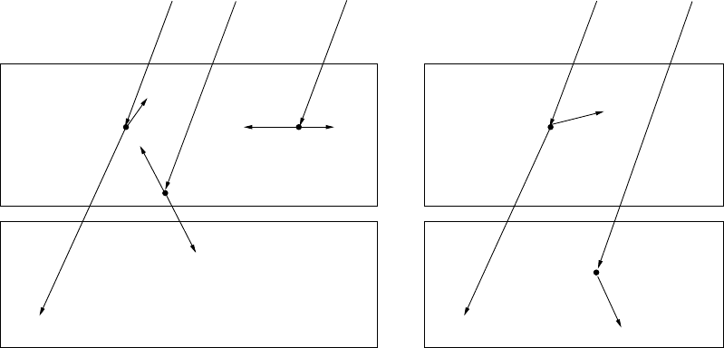
Fig. 6.31 Principle of converter-silicon operation: a)
6
LiF converter, α and tritium (T) produced by neutron interactions with the converter layer
deposit their energy in silicon. T is dominant (see text); b) CH
2
converter, proton recoil produced by the elastic scattering of a neutron on the
protons of the CH
2
converter. A fraction of incident neutrons may traverse the converter film and interact directly with Si.
January 9, 2009 10:21 World Scientific Book - 9.75in x 6.5in ws-bo ok975x65˙n˙2nd˙Ed
512 Principles of Radiation Interaction in Matter and Detection
neutron–nucleus head-on collisions. Then, the energy of the incident neutron is
totally transferred for M
n
= M
R
, i.e., E
n
= E
R
. Therefore, for fast neutrons,
it is advantageous to select converters with high hydrogen content and restrain
the amount of heavier atoms which reduce E
R
and absorb the energy of charged
secondaries. Polyethylene (CH
2
) appears to be an optimal choice as converter for
fast neutrons.
6.7.1.1 Signal in Silicon Detectors for Thermal Neutrons
Standard assumptions are made to estimate the signal generated in a silicon detector
by thermal neutrons [McGregor et al. (2003); Wielunski et al. (2004)]. A silicon
detector, 300 µm thick with no dead layer, is considered with a converter layer
put in front (Fig. 6.31). As reminded above, the efficiency of this type of detector
for heavy charged particles is 100%. The flux of thermal neutrons (Sect. 4.1.3.2)
is assumed to be independent of the depth d of the (thin) converter. The heavy
charged particles produced by the thermal neutron interactions in the converter
material have their direction of emission kinematically constrained. Only one of the
charged particle reaction products, which are emitted in opposite directions, may
cross the converter layer-detector interface into silicon. Being heavy, these charged
particles practically travel in straight lines in the converter. The range, R
i
(E), of
these secondary particles in the converter is calculated from SRIM [Ziegler, J.F.
and M.D. and Biersack (2008b)]. Only charged particles produced in the converter
at a distance from the converter layer-detector interface smaller than their range
R
i
(E) in the converter will contribute to the signal in the detector. The probability
of signal generation will then depend on R
i
(E) and on the number, N
n
, of incident
neutrons on the converter. It will also depend on the atomic concentration, N
i
, of
target-isotopes in the converter and on the cross section, σ
i
, of the neutron-i-target
isotope reaction. Coming back to the example of thermal neutron reactions with
6
LiF, as the α-particle and triton travel in opposite directions due to the small
kinetic energy of the thermal neutrons, only one of them will be detected from
one neutron interaction (Fig. 6.31). In practice, α-particles which have larger losses
can hardly leave the converter. Therefore, most of the
α
-particles are stopped in
the converter and do not contribute to the signal (see also [Pospisil (1993)]). In
Fig. 6.31 is also illustrated the case where the α-particle and triton (T) are moving
in opposite direction parallel to the silicon surface and, therefore, never reach the
active volume of the detector and cannot contribute to any signal.
Generally, summing over all particles, i = α, T, produced in the neutron reac-
tion, the probability of signal generation can then be expressed as:
S = Σ
i=α,T
S
i
, (6.137)
where
S
i
= N
n
N
i
σ
i
R
i
P. (6.138)
January 9, 2009 10:21 World Scientific Book - 9.75in x 6.5in ws-bo ok975x65˙n˙2nd˙Ed
Solid State Detectors 513
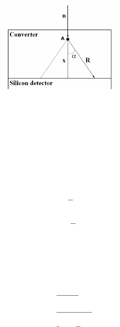
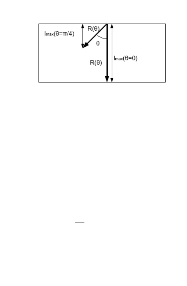
Fig. 6.32 The thermal neutron is produced in A at a distance x from the interface converter-
detector. The opening angle of the cone is α = arccos(x/R).
The factor P in Eq. (6.138) represents the total or integrated geometrical pro-
bability that any charge particle generated in the converter reaches the detector
and produces a signal. This probability is P = 0.25, as calculated below. The point
(vertex), A, is the source of isotropic emission of particles produced by the reaction
of the thermal neutron with an atom of the converter (Fig. 6.32). These particles are
produced in a cone of opening angle α and a particle emitted at angle α stops after
the range R in the converter when its energy has gone down to zero (Fig. 6.32). If
point A is located at a distance x from the cone basis, i.e., the converter layer-silicon
detector interface, one has:
cos α =
x
R
(6.139)
or
α = arccos
³
x
R
´
. (6.140)
The solid angle, SA, of particle emission is then:
SA =
Z
2π
0
Z
α
0
sin θ dθ dφ = 2π (1 − cos α) (6.141)
compared to the total sphere solid angle, SA
sphere
= 4π.
Then, the probability, P , that a particle emitted at point, A, with a range R in
the converter reaches the converter layer-silicon detector interface at a distance x is
P (x, R) =
SA
SA
sphere
=
2π (1 − cos α)
4π
=
1
2
³
1 −
x
R
´
(6.142)

January 9, 2009 10:21 World Scientific Book - 9.75in x 6.5in ws-bo ok975x65˙n˙2nd˙Ed
514 Principles of Radiation Interaction in Matter and Detection
or, introducing the variable η = x/R,
P (η) = 0.5(1 − η). (6.143)
Integrating from η = 0 (origin of the particle at x = 0) up to η = 1 (origin of the
particle at x = R), one obtains:
P ∼ 0.5
Z
1
0
P (η) dη = 0.25. (6.144)
The factor P in Eq. (6.138) representing the total or integrated geometrical
probability that any charge particle generated in the converter goes in a direction
opposite to the converter layer-silicon detector interface shown in Fig. 6.32 can be
expressed as:
P (d − x, R) =
1
2
µ
1 −
d − x
R
. (6.145)
Equation (6.145) is needed when one considers the case of a silicon detector
inserted in between two converter layers.
Using Eqs. (6.137, 6.138) the probability of signal generation per incident neu-
tron can be expressed as:
S
N
n
= Σ
i
S
i
N
n
= Σ
i
N
i
σ
i
R
i
P. (6.146)
As an example of estimate one can calculate the signal expected from thermal
neutrons (neutron energy of 0.025 eV) using a
6
LiF converter (the Fluorine absorp-
tion cross section of 9.6 mb can be neglected compared to the
6
LiF cross section of
940 b). One can see in Table 6.3, that from neutron interaction with
6
LiF, charged
particles possibly contributing to the signal are α (2.05 MeV) and
3
H (2.71 MeV).
The atomic concentration of target-isotopes in
6
LiF is
N
6
LiF
=
Nρ
A
= 6.022 × 10
23
2.635
25.94
= 6.12 × 10
22
atoms/cm
3
,
where N is the Avogadro constant (see Appendix A.2). The ranges of α (2.05 MeV)
and
3
H (2.71 MeV) in
6
LiF, calculated with SRIM [Ziegler, J.F. and M.D. and
Biersack (2008b)], are 6.05 µm and 31.67 µm, respectively. Then, one finds using
Eq. (6.146)
S
N
n
=
S
3H
N
n
+
S
α
N
n
= 4.56 × 10
−2
+ 8.74 × 10
−3
= 5.3 × 10
−2
. (6.147)
The range of the heavy charged particles is limited (6.05 µm in case of alpha
particles and 31.67 µm for tritons). Therefore, if a neutron is captured further away
from the converter-silicon boundary, the heavy charged particles do not reach the
sensitive volume of the silicon detector. Moreover, as already noted before, some
of the heavy charged particles also travel parallel to the silicon surface and do not
reach the detector active volume. The detection efficiency increases initially with
increasing converter thickness because more neutrons are captured in the converter
January 9, 2009 10:21 World Scientific Book - 9.75in x 6.5in ws-bo ok975x65˙n˙2nd˙Ed
Solid State Detectors 515
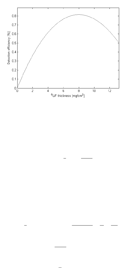
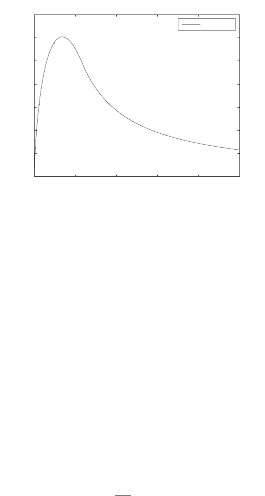
Fig. 6.33 Thermal neutron detection efficiency is shown as a function of the
6
LiF converter
thickness [Gutierrez (2007)]. The LiF converter optimal thickness occurs at 8 mg/cm
2
.
material. However, the detection efficiency starts to decrease at a value, d
opt
, of
LiF thickness. The value of d
opt
is found by using Eq.(6.145), for instance. The
detection efficiency, dP
det
, of a neutron by the system of a converter layer and an
adjacent silicon detector is given by
dP
det
= exp(−µx)
1
2
µ
1 −
d − x
R
µ dx, (6.148)
where µ dx is the probability for the interaction of a neutron with a nucleus in
the converter material at depth x; exp(−µx) is the probability that a neutron will
traverse a path of length x without interaction; 1/2 [1 − (d − x)/R] is the proba-
bility that the products of the interaction reaction of the neutron with a nucleus
of the converter material will escape into the silicon detector. It can be defined as
the ratio between the solid angle defined by the cone whose generatrix equals the
path of the secondary particles in the converter material and the total solid angle
[Eq. (6.145)]. Integrating Eq. (6.148) over the converter thickness (d) one finds
P
det
=
1
2
·
−exp(−µd) + 1 −
exp(−µd)
µR
−
d
R
+
1
µR
¸
. (6.149)
To find the converter optimal thickness, d
opt
, one imposes the condition
dP
det
d(d)
= 0, (6.150)
i.e.,
d
opt
=
1
µ
ln(µR + 1). (6.151)
January 9, 2009 10:21 World Scientific Book - 9.75in x 6.5in ws-bo ok975x65˙n˙2nd˙Ed
516 Principles of Radiation Interaction in Matter and Detection
a)
0 10 20 30 40 50 60 70 80 90
337.5
338
338.5
339
339.5
340
340.5
Recoil angle (in degrees) in the laboratory system
s (q ) [mb/steradian]
E
Incident neutron
=1MeV
b)
0 10 20 30 40 50 60 70 80 90
53.5
54
54.5
55
55.5
56
56.5
57
57.5
58
58.5
Recoil angle (in degrees) in the laboratory system
s (q ) [mb/steradian]
E
Incident neutron
=14MeV
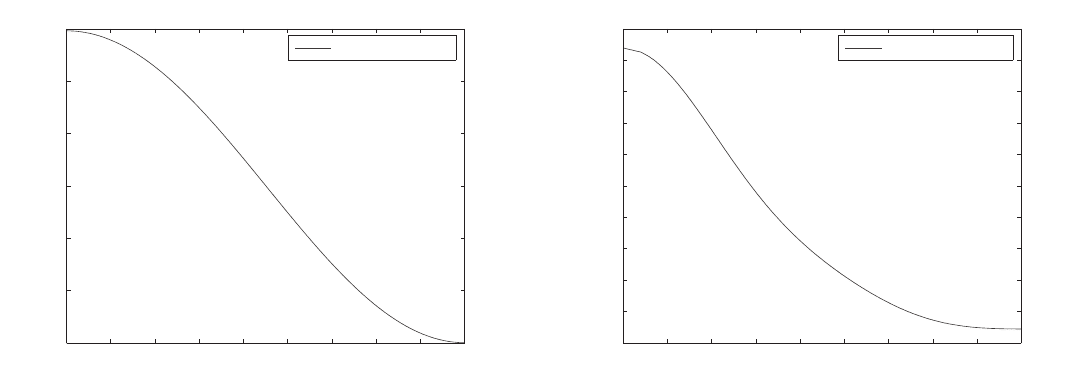
Fig. 6.34 Differential elastic (n,p) cross section as a function of the proton recoil angle (in degrees) in the laboratory system [Gutierrez (2007)]: for
an incoming neutron a) of 1 MeV and b) 14 MeV.
January 9, 2009 10:21 World Scientific Book - 9.75in x 6.5in ws-bo ok975x65˙n˙2nd˙Ed
Solid State Detectors 517
Fig. 6.35 Converter maximal thickness as a function of the proton recoil angle. The incoming
neutrons follow a direction along the normal to the converter area [Gutierrez (2007)].
The tritium signal being about 5 times larger than the α signal (Eq. (6.147)), the
neutron detection efficiency will be maximum when using the
6
LiF optimal thickness
for tritium. Equation (6.151) gives for tritium an optimal
6
LiF converter thickness
d
opt
= 30.4 µm = 8.0 mg/cm
2
. (6.152)
The detection efficiency is shown in Fig. 6.33 as a function of the
6
LiF converter
thickness [Gutierrez (2007)]. A maximum clearly occurs at the thickness of 8 mg/cm
2
which is the LiF converter optimal thickness. The result is in excellent agreement
with the results of Monte Carlo simulations [Uher et al. (2007a)]. For a boron
converter, there are four contributions to the signal (Table 6.3) and Eq. (6.138)
gives:
S
N
n
=
S
Li,I
N
n
+
S
α,I
N
n
+
S
Li,II
N
n
+
S
α,II
N
n
. (6.153)
If one uses
N
10
B
=
N ρ
A
= 13.03 × 10
22
atoms/cm
3
and the values of the cross sections for the neutron nuclear reactions in the
10
B
converter. i.e.,
σ = 3571 b for n +
10
B → α (1.47 MeV) +
7
Li (0.84 MeV) + γ (0.48 MeV)
and
σ = 269 b for n +
10
B → α (1.78 MeV) +
7
Li (1.01 MeV),
one finds:
S
N
n
= 2.04 ×10
−2
+ 4.23 ×10
−2
+ 1.73 ×10
−3
+ 3.96 ×10
−3
= 6.84 ×10
−2
. (6.154)
The ranges of
7
Li (0.84 MeV), α (1.47 MeV),
7
Li (1.01 MeV) and α (1.78 MeV)
in
10
B, calculated with SRIM [Ziegler, J.F. and M.D. and Biersack (2008b)], are
1.75 µm, 3.62 µm, 1.97 µm and 4.5 µm, respectively. Higher neutron reaction cross
sections in
10
B is compensated by smaller ranges and therefore sensitivities achieved
with
10
B and
6
LiF converters are comparable.
January 9, 2009 10:21 World Scientific Book - 9.75in x 6.5in ws-bo ok975x65˙n˙2nd˙Ed
518 Principles of Radiation Interaction in Matter and Detection
0 20 40 60 80 100
0
0.02
0.04
0.06
0.08
0.1
0.12
0.14
CH
2
thickness [m m]
Proton detection probability
E
n
= 1MeV
Fig. 6.36 Proton detection probability as a function of the polyethylene thickness (in µm) for
incident neutron energy of 1 MeV. This indirectly measures also the fast neutron detection proba-
bility [Gutierrez (2007)].
6.7.1.2 Signals in Silicon Detectors by Fast Neutrons
These signals are produced by the elastic scattering of fast neutrons on nuclei in
the converter. As discussed in Sect. 6.7.1, CH
2
being hydrogen-rich is an optimal
choice of converter for the detection of fast neutron with silicon detectors. In that
case, the detection efficiency, S
eff
, of a Si detector as a function of the converter
thickness d can be expressed as
S
eff
= ²
p
N
0
¡
1 − e
−Σd
¢
e
−µd
+ ²
n
N
0
e
−Σd
, (6.155)
where ²
p
is the intrinsic efficiency for recoil protons (assumed to be 1 as all the
protons reaching the detector generate a signal, 100% charge collection efficiency), ²
n
is the intrinsic detection for direct neutron detection (a fraction of neutron can cross
the converter and produce signals in Si through nuclear reactions, like Si(n,p)Al
and Si(n,α)Mg). In Eq. 6.155, the term ²
p
N
0
¡
1 − e
−Σd
¢
e
−µd
represents the flux of
recoiling protons produced by neutron interactions with the CH
2
converter nuclei,
Σ (cm
−1
) is the mean macroscopic neutron-converter cross section. In the case of
polyethylene,
Σ (cm
−1
) =
ρ N
A
(n
H
σ
H
+ n
C
σ
C
)
and µ is the proton absorption coefficient in the converter, which can be calcu-
lated from SRIM [Ziegler, J.F. and M.D. and Biersack (2008b)]. Parametrisation of
σ
H
and σ
C
as functions of energy may be found in [Mesquita, Filho and Hamada
January 9, 2009 10:21 World Scientific Book - 9.75in x 6.5in ws-bo ok975x65˙n˙2nd˙Ed
Solid State Detectors 519
(2003)], for instance. The term ²
n
N
0
e
−Σ d
represents the fraction of neutrons travers-
ing the converter film and interacting directly with Si. The coefficient N
0
is the rate
of neutrons emitted from a source of neutrons (such as an Am-Be source). Equa-
tion (6.155) can be fitted to the data to obtain the detection efficiency (count rate)
as a function of the converter thickness. For normal incidence, the number of signals
per incident fast neutron is given by a formula similar [Wielunski et al. (2004)] to
Eqs. (6.137, 6.138) or (6.146)
S
N
n
= Σ
i
S
i
N
n
= Σ
i
N
i
σ
i
(E
n
, θ) R
i
[E
R
(E
n
, θ)] P (E
n
), (6.156)
where E
n
is the incident neutron energy, N
n
the number of incident neutrons on
the converter, N
i
the atomic concentration of the target-i-isotopes in the conver-
ter; σ
i
(E
n
, θ) is the neutron-i-target isotope elastic scattering cross section and
R
i
[E
R
(E
n
, θ)] is the range of the recoil-i produced by the neutron-i-target isotope
elastic scattering. The (n,p) differential elastic cross section for an incident neutron
of given energy is [Hopkins and Breit (1971)]
σ(θ) = Σ
l
i=l
c
i
P
i
¡
1 − 2 cos
2
θ
¢
, (6.157)
where P
i
is the ith order Legendre polynomial, θ the scattering angle in the labora-
tory frame. The differential elastic cross section for proton recoil as a function of the
recoil angle (laboratory frame) is given in Fig. 6.34 for 1 MeV and 14 MeV incident
neutrons. From Fig. 6.34, for b oth energies, there are more protons forward emitted
(θ = 0).
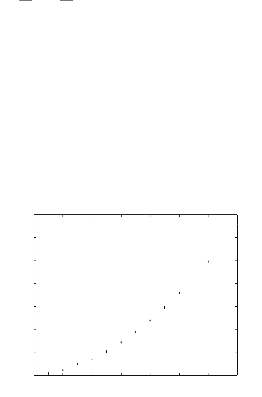
0 2 4 6 8 10 12 14
0
200
400
600
800
1000
1200
1400
CH
2
optimal thickness [µm]
Neutron energy [MeV]
Fig. 6.37 CH
2
optimal thickness (µm) as a function of the incident neutron energy (MeV) [Gutier-
rez (2007)].