Lyons W.C. (ed.). Standard handbook of petroleum and natural gas engineering.2001- Volume 1
Подождите немного. Документ загружается.

MWD
and
LWD
1065
4000
6000
8000
g
10000
al
n
12000
14000
-
-
-
-
-
1.0 1.2
1.4 1.6
1.8
2.0
2.2
d-exp
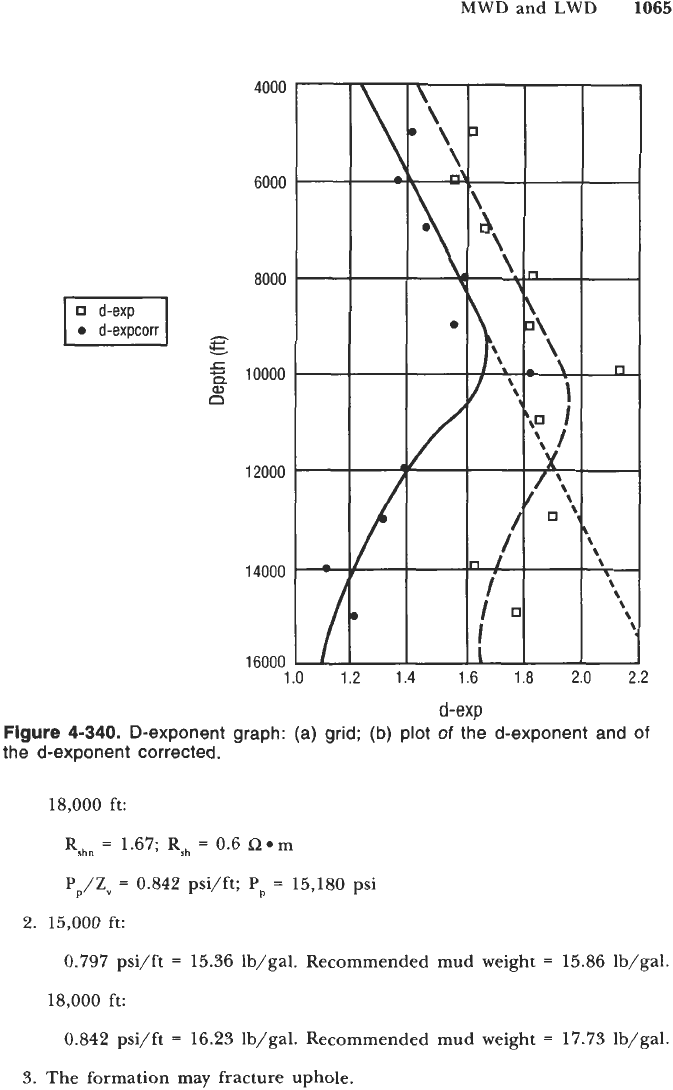
Figure
4-340.
D-exponent graph: (a) grid;
(b)
plot
of
the d-exponent and
of
the d-exponent corrected.
18,000 ft:
Rshn
=
1.67; Rsh
=
0.6 Rem
Pp/Zv
=
0.842 psi/ft;
Pp
=
15,180 psi
2.
15,000
ft:
0.797 psi/ft
=
15.36 lb/gal. Recommended mud weight
=
15.86 lb/gal.
18,000 ft:
0.842 psi/ft
=
16.23 lb/gal. Recommended mud weight
=
17.73 lb/gal.
3.
The formation may fracture uphole.
1066
Drilling and Well Completions
Y
W
n
14
16
18
-
20
22
HUMBLE
OIL
&
REFINING COMPANY
PECAN ISLAND
VERMILION PARISH, LOUISIANA
EQUATION
OF
THE NORMAL TREND
FISH
=
AxEXP (BxDEPTH)
A
=
0.475854
B=0.000070
lo-'
2
3
4
5
6
7
89100
2
3
4
5
6
78910
SHALE
RESISTIVITY
(RSH)
OHM-METER
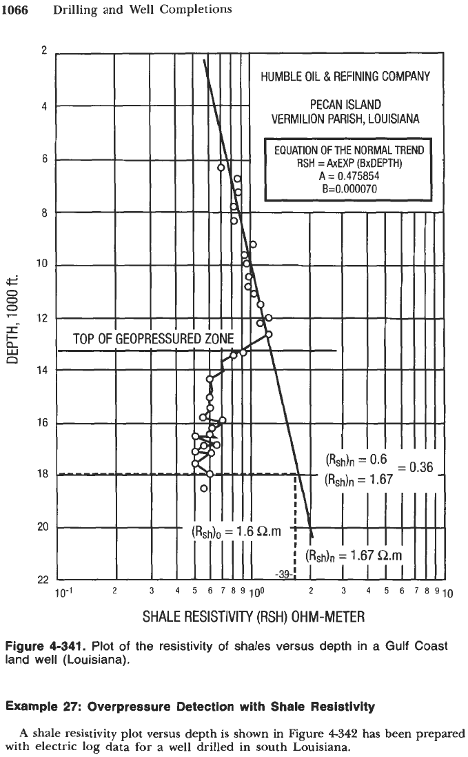
Figure
4-341.
Plot
of
the resistivity
of
shales versus depth in a
Gulf Coast
land well (Louisiana).
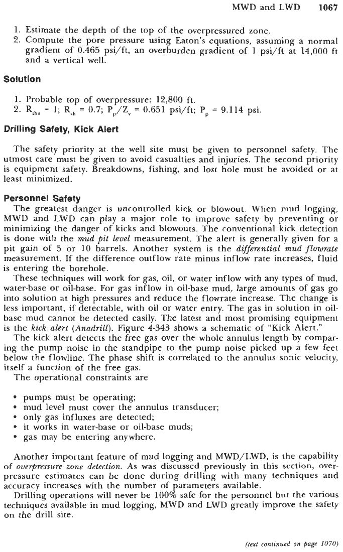
Example
27:
Overpressure
Detection
with
Shale
Resistivity
A
shale resistivity plot versus depth
is
shown in Figure
4342
has been prepared
with electric log data
for
a well drilled in south Louisiana.
MWD and LWD
1067
1.
Estimate the depth of the top of the overpressured zone.
2.
Compute the pore pressure using Eaton’s equations, assuming a normal
gradient of
0.465
psi/ft, an overburden gradient of
1
psi/ft at
14,000
ft
and a vertical well.
Solution
1.
Probable top of overpressure:
12,800
ft.
2.
Rrhn
=
1;
Rsh
=
0.7;
PJZV
=
0.651
psi/ft;
Pp
=
9.114
psi.
Drilling Safety,
Kick
Alert
The safety priority at the well site must be given to personnel safety. The
utmost care must be given to avoid casualties and injuries. The second priority
is
equipment safety. Breakdowns, fishing, and lost hole must be avoided or at
least minimized.
Personnel Safety
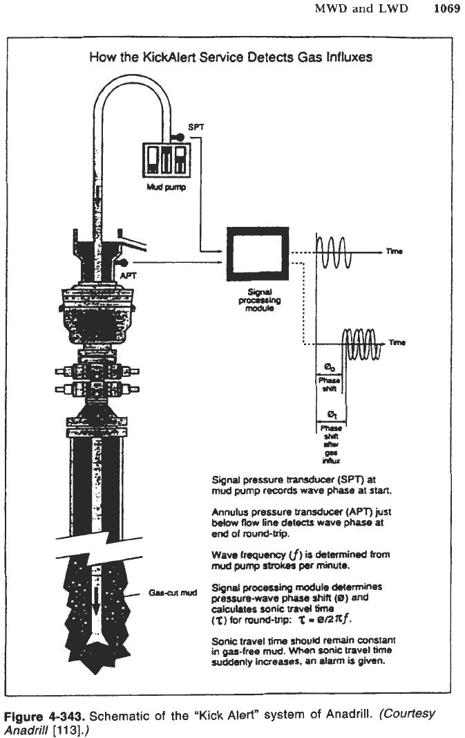
The greatest danger is uncontrolled kick or blowout. When mud logging,
MWD and LWD can play a major role to improve safety by preventing or
minimizing the danger of kicks and blowouts. The conventional kick detection
is done with the
mud pit level
measurement. The alert is generally given for a
pit gain of
5
or
10
barrels. Another system is the
dqferential mud flowrate
measurement. If the difference outflow rate minus inflow rate increases, fluid
is
entering the borehole.
These techniques will work for gas, oil, or water inflow with any types of mud,
water-base or oil-base. For gas inflow in oil-base mud, large amounts of gas go
into solution at high pressures and reduce the flowrate increase. The change is
less important,
if
detectable, with oil or water entry. The gas in solution in oil-
base mud cannot be detected easily. The latest and most promising equipment
is the
kick alert (Anadrill).
Figure
4-343
shows a schematic of “Kick Alert.”
The kick alert detects the free gas over the whole annulus length by compar-
ing the pump noise in the standpipe to the pump noise picked up a few feet
below the flowline. The phase shift
is
correlated to the annulus sonic velocity,
itself a function of the free gas.
The operational constraints are
pumps must be operating;
mud level must cover the annulus transducer;
only gas influxes are detected;
it works in water-base or oil-base muds;
gas may be entering anywhere.
Another important feature of mud logging and MWD/LWD, is the capability
of
overpressure zone detection.
As was discussed previously in this section, over-
pressure estimates can be done during drilling with many techniques and
accuracy increases with the number of parameters available.
Drilling operations will never be
100%
safe for the personnel but the various
techniques available in mud logging, MWD and LWD greatly improve the safety
on the drill site.
(text continued on page
1070)
10-1
2
3
4
5
6
789100
2
3
4
5
6
78910
SHALE
RESISTIVITY
(RSH) OHM-METER
Figure
4-342.
Plot
of
the resistivity
of
shales versus depth
in
a Gulf Coast
land
well (Louisiana).
MWD
and
LWD
1069
How
the KickAlert Service Oetects
Gas
Influxes
.Rn
0.r
hhu
Signal pressure
haruducer
(SPT)
at
mud
pump
records
wave phase at
start.
Annulus
pressure
transducer
(APT)
just
below
#ow line detecIs wave
phase
at
end
of
round-trip.
wave
frequency
cf)
is detmined
from
mod
pump
strokes
per
minute.
Sinal
processing
module determines
pressure-wave phase
shii
(0)
and
calculates sonic travel
time
(t)
for
round-trip:
‘t
=
01~xf.
Sonic
travel
time
should
remain constant
in gas-free
mud.
When sonic travel
time
suddenly increases. an alarm
is
given.
Figure
4-343.
Schematic
of
the
“Kick
Alert” system
of
Anadrill.
(Courtesy
Anadrill
[
11
31.)
1070
Drilling and Well Completions
(text
continued
from
page
1067)
Equipment Safety.
The greatest risk for the equipment is sticking the drillstring.
Before MWD, the drilling personnel had to rely on surface measurements only.
The drilling parameters can now be measured practically “at the bit.” Calcula-
tions
of
drag and friction can be carried out in real-time alerting the driller
of
any danger of pipe sticking.
Downhole flowrate measurements indicate drillstring washouts before the
drillstring breaks and, consequently, avoiding expensive and dangerous fishing.
Bit efficiency calculated in real time gives an indication that the drill bit is
damaged and that cones may be lost. Downhole vibration and shock measure-
ments are also valuable indicators used to avoid damaging the drillstring.
All of these MWD measurements are definitively improving safety, minimizing
breakdowns and making drilling more efficient.
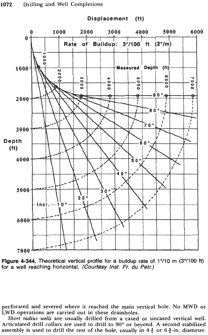
Horizontal Drilling, Geosteering
To
attain higher performances, the oil and gas companies are demanding greater
drilling efficiency in conditions such as extended reach and horizontal drilling. The
improved production and return on investment can be achieved from fewer wells,
but better quality wells. Figures
4344
and
4345
show the theoretical vertical profile
for a buildup to horizontal with respectively
lo/10
m
(3O/lOO
ft) and
2”/10
m
(So/
100
ft). In the first case, the distance below kick-off point
(KOP)
to reach horizontal
is
570
m
(2,870
ft)
TVD,
with
a
measured depth of
900
m
(2,952
ft). In the second
case, the corresponding lengths are
290
m
(951
ft)
and
450
m
(1,476
ft).
To follow accurately the theoretical trajectory, MWD techniques must be used.
When the borehole is near horizontal, logging
or
surveying tools cannot be
lowered by gravity anymore. They must be pumped down the drillpipes
for
directional measurements. Conventional logging has to be carried out by conveying
the logging sondes downhole at the tip of the drillstring. The logging operation
becomes long, expensive and dangerous. A much more efficient way is to survey
the trajectory and record the logs while drilling. The logging data can be used to
ascertain that the borehole is being drilled in the anticipated pay zone. If not,
immediate remedial action is taken to %teer” the well towards the pay zone. The
most advanced technique in use today is the
“geosteering” technique.
Geosteering is usually done with a mud motor.
A
mud motor with bent sub
allows changing of orientation and inclination without pulling the drillstring out.
Steering is done by rotating it a small angle.
In
classical geosteering
the sensors for inclination, azimuth, drilling parameters,
and logging are located above the mud motor and the distances may be in the
order of those shown in Figure
4-296
that is
30
ft or more above the drill bit.
Although radial measurements can be performed to verify that the borehole is
being drilled in the pay zone, it is often too late to make a correction and the bore-
hole leaves the pay zone.
The new geosteering system offers measurements “at the bit” (below the mud
motor) of inclination, rpm, azimuthal gamma ray, azimuthal resistivity, and bit
resistivity as seen in Figure
4298.
The signals are transmitted electromagnetically
to the MWD sub located above the mud motor, then relayed to surface with
the standard mud pressure transmission system. To summarize, the following is
recorded just above the drill bit:
inclination
revolution per minute
MWD and LWD
1071
azimuthal gamma ray
azimuthal resistivity
bit resistivity
Above the mud motor, the following is recorded:
weight-on-bit
torque
inclination
azimuth
tool face
neutron
density
Pe
Other parameters, such as alternator voltage (for flowrate), temperature and
pressure, can also be monitored.
A frame of
16
words of information can be updated in
27
s
at a rate of
6
bits/s. Even at
100
ft/hr of drilling rate (never reached in horizontal drilling),
updating would occur every
0.75
ft.
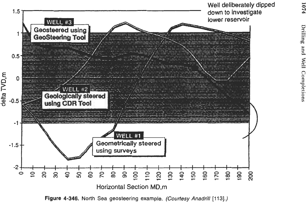
An example of three horizontal wells drilled in a
2
m
(6
ft)
in the North Sea
is shown in Figure
4-346.
Well
No.
1
was drilled with inclination and azimuth data only. The sensors
were located above the mud motor. Only a short section
(63
m;
207
ft)
was
drilled in the reservoir.
Well
No.
2
was “geologically” steered by adding gamma ray and resistivity
capability. Only a short section is out of the reservoir, making a total of 168
m
(552
ft) in the reservoir.
Well
No.
3
was steered with the new geosteering system.
A
smooth trajectory
was obtained with the whole interval in the reservoir. The last section was
dipped intentionally to investigate the lower reservoir.
We see that horizontal drilling can be carried out satisfactorily if the following
is available:
sophisticated MWD/LWD technology
computer capability
positive displacement motor
Suggestions have been made recently to drill
horizontal brunches
in the hori-
zontal portion of the horizontal wells. If this technique is developed, the
drainage capacity of horizontal wells
will
be even better.
Types
of
Directional Drilling
Horizontal drilling
is
performed using “long radius” of curvature to reach
horizontal:
1
to
2”/10
m
(3
to
6O/lOO
ft). Attempts have been made for years
to improve production with medium, short and ultrashort radius of curvature.
The sketch of Figure
4-347
shows the four types of curvatures
[127].
Table
4-137
gives the range of values of radius, angle change with depth, and
usual horizontal lengths drilled in each case.
Ultrashort radius
wells
are usually called “drainholes.” They are drilled with
special equipment and completed with
1$
to 24-in. tubing. The tubing is
1072
Drilling and Well Completions
Displacement
(ft)
0
1000
2000
3000 4000
5000
6000
Figure
4-344.
Theoretical vertical profile
for
a buildup rate of
1
"/lo
m
(3"/100
ft)
for
a well reaching horizontal.
(Courtesy
Inst.
Fr.
du
Petr.)
perforated and severed where it reached the main vertical hole.
No
MWD
or
LWD
operations are carried out in these drainholes.
Short
radius
wells
are usually drilled from a cased or uncased vertical well.
Articulated drill collars are used to drill to 90'
or
beyond.
A
second stabilized
assembly is used to drill the rest of the hole, usually in
4
3
or
6
+-in. diameter.
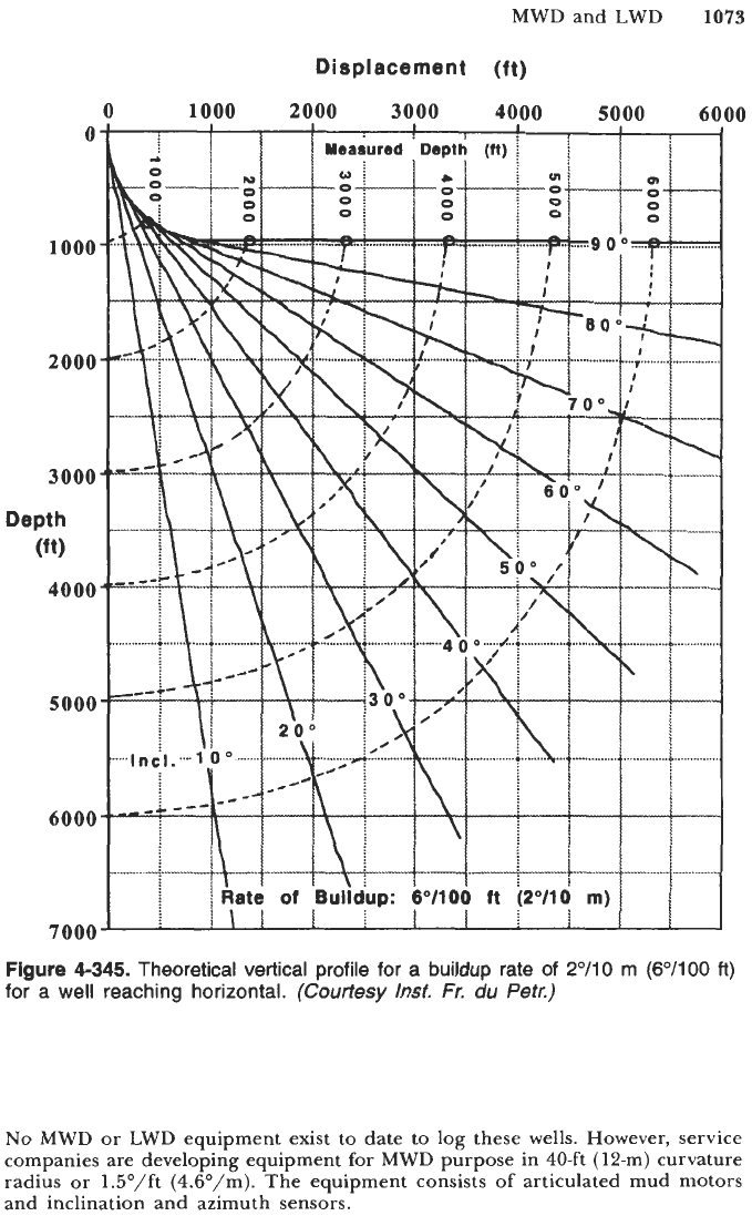
Figure
4-345.
Theoretical vertical profile for a
buildup
rate
of
2"/10
m
(6"/100
ft)
for a
well
reaching horizontal.
(Courtesy
Inst.
Fr.
du
Petr.)
No
MWD or LWD equipment exist
to
date
to
log these wells. However, service
companies are developing equipment for MWD purpose in 40-ft (12-m) curvature
radius or 1.5"/ft (4.6"/m). The equipment consists of articulated mud motors
and inclination and azimuth sensors.
Well
deliberately dipped
down
to investigate
1.5
I
c
0
4
rp
1
0.5
E
go
rn
'0
c
-
CD
-0.5
-1
-1.5
t
I
I1
I1
I
I
II
111
I
I
IIIII
Ill
Ill
IIIIIIIII
Horizontal
Section
MD,m
Figure 4-346.
North
Sea geosteering example.
(Courtesy
Anadrill
[I
131.)