Lyons W.C. (ed.). Standard handbook of petroleum and natural gas engineering.2001- Volume 1
Подождите немного. Документ загружается.

Downhole Motors
885
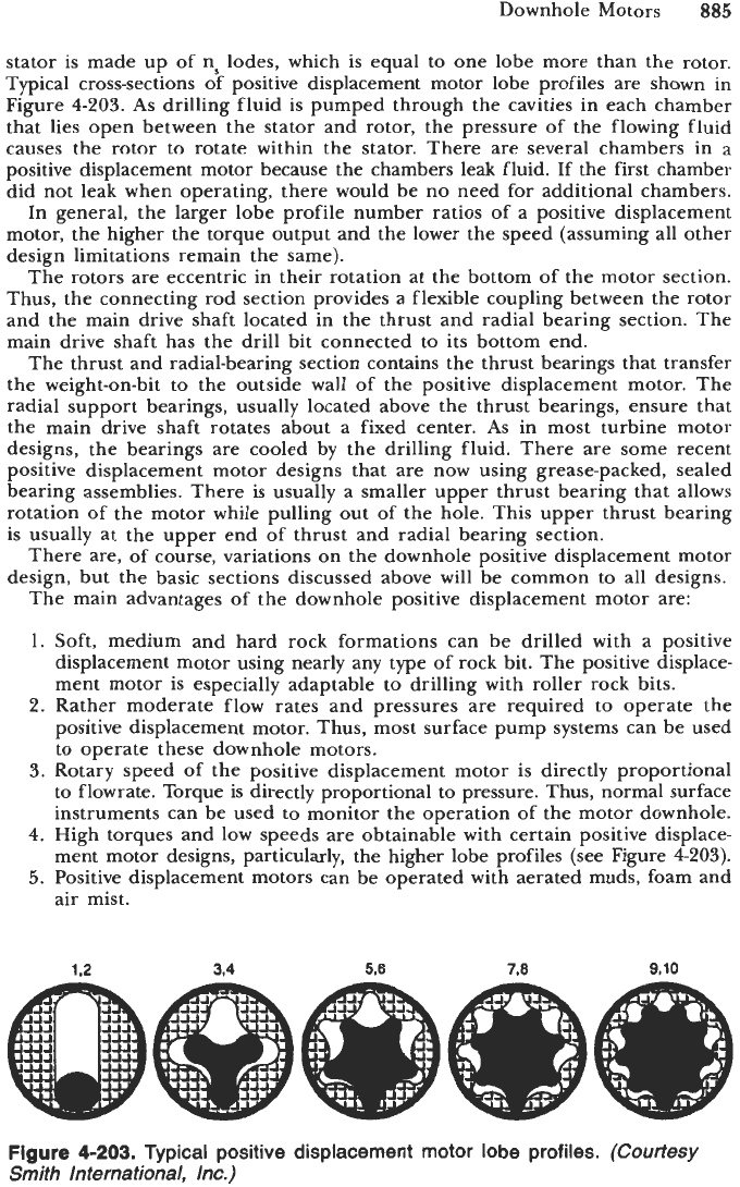
stator is made up of ns lodes, which is equal to one lobe more than the rotor.
Typical cross-sections of positive displacement motor lobe profiles are shown in
Figure
4-203.
As
drilling fluid is pumped through the cavities in each chamber
that lies open between the stator and rotor, the pressure of the flowing fluid
causes the rotor to rotate within the stator. There are several chambers in a
positive displacement motor because the chambers leak fluid. If the first chamber
did not leak when operating, there would be no need for additional chambers.
In general, the larger lobe profile number ratios of a positive displacement
motor, the higher the torque output and the lower the speed (assuming all other
design limitations remain the same).
The rotors are eccentric in their rotation at the bottom of the motor section.
Thus, the connecting rod section provides a flexible coupling between the rotor
and the main drive shaft located in the thrust and radial bearing section. The
main drive shaft has the drill bit connected to its bottom end.
The thrust and radial-bearing section contains the thrust bearings that transfer
the weight-on-bit to the outside wall of the positive displacement motor. The
radial support bearings, usually located above the thrust bearings, ensure that
the main drive shaft rotates about a fixed center.
As
in most turbine motor
designs, the bearings are cooled by the drilling fluid. There are some recent
positive displacement motor designs that are now using grease-packed, sealed
bearing assemblies. There is usually a smaller upper thrust bearing that allows
rotation of the motor while pulling out of the hole. This upper thrust bearing
is usually at the upper end of thrust and radial bearing section.
There are, of course, variations on the downhole positive displacement motor
design, but the basic sections discussed above will be common to all designs.
The main advantages of the downhole positive displacement motor are:
1.
Soft, medium and hard rock formations can be drilled with a positive
displacement motor using nearly any type of rock bit. The positive displace-
ment motor is especially adaptable to drilling with roller rock bits.
2.
Rather moderate flow rates and pressures are required to operate the
positive displacement motor. Thus, most surface pump systems can be used
to operate these downhole motors.
3.
Rotary speed of the positive displacement motor is directly proportional
to flowrate. Torque
is
directly proportional to pressure. Thus, normal surface
instruments can be used to monitor the operation of the motor downhole.
4.
High torques and low speeds are obtainable with certain positive displace-
ment motor designs, particularly, the higher lobe profiles (see Figure
4203).
5.
Positive displacement motors can be operated with aerated muds, foam and
air mist.
1.2
3.4 5.6 7.8
9,lO
Figure
4-203.
Typical positive displacement motor lobe profiles.
(Courtesy
Smith International, Inc.)
886
Drilling and Well Completions
The main disadvantages of the downhole positive displacement motors are:
1.
When the rotor shaft of the positive displacement motor is not rotating,
the surface pump pressure will rise sharply and little fluid will pass through
the motor.
2. The elastomer of the stator can be damaged by high temperatures and
some hydrocarbons.
Operations
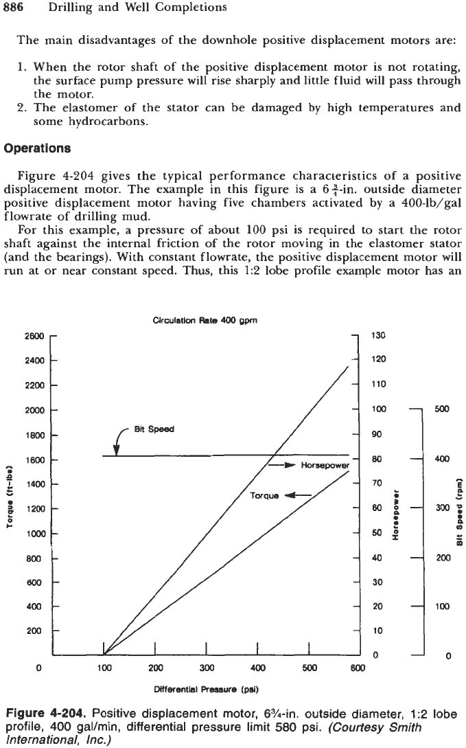
Figure 4-204 gives the typical performance characteristics of a positive
displacement motor. The example in this figure is a 6+-in. outside diameter
positive displacement motor having five chambers activated by a 400-lb/gal
flowrate of drilling mud.
For this example, a pressure of about
100
psi is required to start the rotor
shaft against the internal friction of the rotor moving in the elastomer stator
(and the bearings). With constant flowrate, the positive displacement motor will
run at or near constant speed. Thus, this
1:2
lobe profile example motor has an
Circulation
Rate
400
gpm
9
K
I-
130
120
110
100
90
80
40
30
20
10
0
100
200
300
400
500
800
Differential Pressure
(psi)
Figure
4-204.
Positive displacement motor, 63/44. outside diameter,
1
:2
lobe
profile,
400
gal/min, differential pressure limit
580
psi.
(Courtesy Smith
International, Inc.)
Downhole Motors
887
operating speed of
408
rpm. The torque and the horsepower of the positive
displacement motor are both linear with the pressure drop across the motor.
Therefore, as more weight is placed on the drill bit (via the motor), the greater
is the resisting torque
of
the rock. The mud pumps can compensate for this
increased torque by increasing the pressure on the constant flowrate through
the motor. In this example the limit in pressure drop across the motor
is
about
580
psi. Beyond this limit there will be either extensive leakage or damage to
the motor, or both.
If the positive displacement motor is lifted off the bottom of the borehole
and circulation continues, the motor will simply continue to rotate at 408 rpm. The
differential pressure, however, will drop to the value necessary to overcome
internal friction and rotate, about 100 psi. In this situation the motor produces
no drilling torque or horsepower.
As
the positive displacement motor is lowered and weight is placed on the
motor and thus the bit, the motor speed continues but the differential pressure
increases, resulting in an increase in torque and horsepower.
As
more weight
is
added to the positive displacement motor and bit, the torque and horsepower
will continue to increase with increasing differentiated pressure (Le., standpipe
pressure). The amount
of
torque and power can be determined by the pressure
change at the standpipe at the surface between the unloaded condition and the
loaded condition. If too much weight is placed on the motor, the differential
pressure limit for the motor will be reached and there
will
be leakage or a
mechanical failure in the motor.
The rotor of the Moineau-type positive displacement motor has a helical
design. The axial wave number
of
the rotor is one less than the axial wave
number for the stator for a given chamber. This allows the formation of a series
of fluid cavities as the rotor rotates. The number
of
stator wave lengths n, and
the number of rotor wave lengths nr per chamber are related by
[79,86]
n,
=
nr
+
1
(4-1 54)
The rotor is designed much like a screw thread. The rotor pitch is equivalent
to the wavelength of the rotor. The rotor lead is the axial distance that a wave
advances during one full revolution of the rotor. The rotor pitch and the stator
pitch are equal. The rotor lead and stator lead are proportional to their
respective number of waves. Thus, the relationship between rotor pitch tr (in.)
and stator pitch, ts (in.) is
[86]
tr
=
t$
(4-155)
The rotor lead
Lr
(in.) is
Lr
=
nrtr
The stator lead
Ls
(in.) is
(4-
156)
Ls
=
nsts
(4-
157)
The specific displacement per revolution of the rotor is equal to the cross-
sectional area of the fluid multiplied by the distance the fluid advances. The
specific displacement
s
(in.3) is
s
=
nrnstrA
(4- 158)
888
Drilling and Well Completions
where
A
is the fluid cross-sectional area (in.2), The fluid cross-sectional area is
approximately
A
--
2ne:(n:
-
1)
(4- 159)
where er is the rotor rotation eccentricity (in.). The special case of a 1:2 lobe
profile motor has a fluid cross-sectional area of
A
--
2erdr (4-160)
where dr is the reference diameter of the motor (in.). The reference diameter is
dr
=
2epS
(4- 16
1)
For the 1:2 lobe profile motor, the reference diameter is approximately equal
to the diameter of the rotor shaft.
The instantaneous torque of the positive displacement motor
M
(ft-lb) is
M
=
0.0133s Apq (4-1 62)
where Ap
=
differential pressure loss through the motor in psi
11
=
total efficiency of the motor. The 1:2 lobe profile motors have efficien-
cies around
0.80.
The higher lobe profile motors have efficiencies
that are lower (Le., of the order of 0.70 or less)
The instantaneous speed of the positive displacement motor
N
(rpm) is
231.016q
N=
S
(4-163)
where q is the circulation flowrate (gal/min).
The positive displacement motor horsepower
HP
(hp) for any speed is
9*P
1,714
HP
=
-
(4-1 64)
The number of positive displacement motor chambers nc is
where
L
is the length of the actual motor section (in.).
which is
The maximum torque
Mma
will be at the maximum differential pressure Apmm,
M,,
=
0.133s
Ap,,q
(4-1 66)
The maximum horse power
HPmu
will also be at the maximum differential
pressure Ap,,, which is
Downhole Motors
889
-
9*P,a%
HP,,
-
-
1,714
'
(4-1
67)
It should be noted that the positive displacement motor performance param-
eters are independent of the drilling mud weight. Thus, these performance
parameters will vary with motor design values and the circulation flowrate.
If the above performance parameters for a positive displacement motor design
are known for a given circulation flowrate (denoted as
l),
the performance
parameters
for
the new circulation flowrate (denoted
as
2)
can be found by the
following relationships:
Torque
M,
=
MI
Speed
N2
=
(
$)Nl
Power
HP,
=
2
HP,
k
1
(4-1
68)
(4-169)
(4-170)
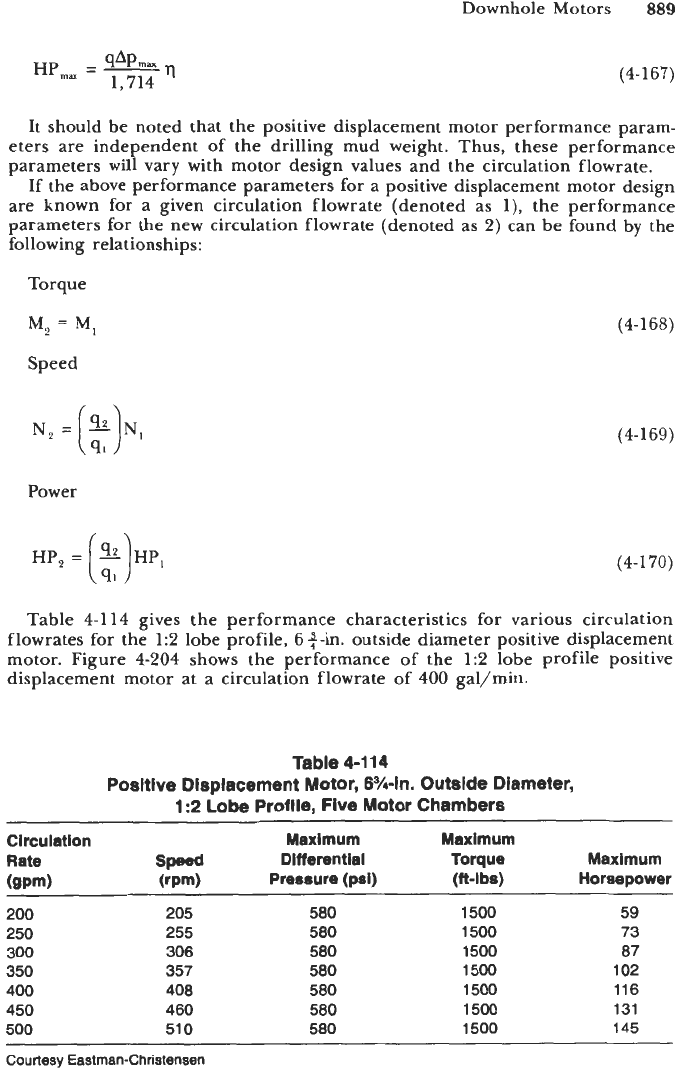
Table
4-1 14
gives the performance characteristics for various circulation
flowrates for the
1:2
lobe profile,
6
$-in. outside diameter positive displacement
motor. Figure
4-204
shows the performance of the
1:2
lobe profile positive
displacement motor at a circulation flowrate of
400
gal/min.
Table
4-1 14
Positive Displacement Motor,
6?4-in,
Outside Diameter,
1:2
Lobe
Profile,
Five
Motor Chambers
~~____
~
Circulation
Rate
(gpm)
200
250
300
350
400
450
500
~~____
~
Maximum
speed
Differential
(rpm) Pressure (psi)
205 580
255 580
306 580
357 580
408 580
460 580
510 580
Maximum
Torque
(ft-lbs)
Maximum
Horsepower
1500
1500
1500
1500
1500
1500
1500
59
73
87
102
116
131
145
~~ ~ ~
Courtesy Eastman-Christensen
890
Drilling and Well Completions
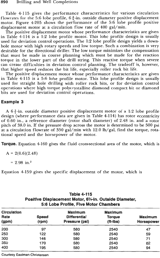
Table
4-1 15
gives the performance characteristics for various circulation
flowrates
for
the
5:6
lobe profile,
6
$-in. outside diameter positive displacement
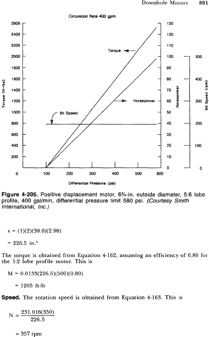
motor. Figure
4-205
shows the performance of the
5:6
lobe profile positive
displacement motor at a circulation flow rate of
400
gal/min.
The positive displacement motor whose performance characteristics are given
in Table
4-114
is a
1:2
lobe profile motor. This lobe profile design is usually
used for deviation control operations. The
1:2
lobe profile design yields a down-
hole motor with high rotary speeds and low torque. Such a combination is very
desirable for the directional driller. The low torque minimizes the compensation
that must be made in course planning which must be made for the reaction
torque in the lower part of the drill string. This reactive torque when severe
can create difficulties in deviation control planning. The tradeoff is, however,
that higher speed reduces the bit life, especially roller rock bit life.
The positive displacement motor whose performance characteristics are given
in Table
4-115
is a
5:6
lobe profile motor. This lobe profile design is usually
used for straight hole drilling with roller rock bits, or for deviation control
operations where high torque polycrystalline diamond compact bit or diamond
bits are used for deviation control operations.
Example
3
A
6+-in. outside diameter positive displacement motor of a
1:2
lobe profile
design (where performance data are given in Table
4-114)
has rotor eccentricity
of
0.60
in., a reference diameter (rotor shaft diameter) of
2.48
in. and a rotor
pitch of
38.0
in. If the pressure drop across the motor is determined to be
500
psi
at a circulation flowrate of
350
gal/min with
12.0
lb/gal, find the torque, rota-
tional speed and the horsepower of the motor.
Torque.
Equation
4-160
gives the fluid cross-sectional area of the motor, which
is
A
=
2(0.6)(2.48)
=
2.98
in.*
Equation
4-159
gives the specific displacement of the motor, which is
Table 4-115
Positive Displacement Motor, 6%-in. Outside Diameter,
5:6 Lobe Profile, Five Motor Chambers
Circulation
Maximum Maximum
Rate
Speed
Dlff
erential Torque Maximum
(gpm)
(rpm) Pressure (psi)
(ft-lbs)
Horsepower
200
250
300
350
400
97
122
146
170
195
580
580
580
580
580
~~
2540
2540
2540
2540
2540
47
59
71
82
94
Courtesy Eastman-Christensen
Downhole Motors
891
2800
2400
2200
2ooo-
1800
-
1800-
n
-
&
1400-
-
0
p
1200
loo0
800-
800-
400
200
0
+
Circulation
Rate
400
gpm
r
-
-
-
-
-
-
-
130
120
110
100
500
90
400
E
P
"
U
70
5
I
50
40
200
30
100
10
800
2o
0
1
0
0
100
200
300
4w
500
Differential
Ressure
(psi)
Figure
4-205.
Positive displacement motor, 6Y4-in. outside diameter, 5:6 lobe
profile,
400
galhin, differential pressure limit
580
psi.
(Courtesy
Smith
International, Inc.)
s
=
(1)(2)(38.0)(2.98)
=
226.5
The torque is obtained from Equation 4-162, assuming an efficiency of 0.80 for
the 1:2 lobe profile motor. This is
M
=
0.0
133( 226.5)( 500)( 0.80)
=
1205 ft-lb
Speed.
The rotation
speed is obtained from Equation 4-163. This is
231.016(350)
226.5
N=
=
357 rpm
892
Drilling and Well Completions
Horsepower.
The horsepower the motor produces is obtained from Equation
4-164.
This is
(0.80)
350( 500)
1714
HP
=
=
82
Planning for a positive displacement motor run and actually drilling with such
a motor is easier than with a turbine motor. This is mainly due to the fact that
when a positive displacement motor is being operated, the operator can know
the operating torque and rotation speed via surface data. The standpipe pressure
will yield the pressure drop through the motor, thus the torque. The circulation
flowrate will yield the rotational speed.
Example
4
A
6
4
-in. outside diameter positive displacement motor (whose performance
data are given in Tables
4-114
and
4-115)
is to be used for a deviation control
direction drill operation. The motor will use an 84411. diameter roller rock bit for
the drilling operation. The directional run is to take place at a depth of
10,600
ft
(measured depth). The rock formation to be drilled is classified as medium, and it
is anticipated that
30
ft/hr will be the maximum possible drilling rate. The mud
weight is to be
11.6
Ib/gal. The drilling rig has a National Supply Company
duplex mud pump Model
E-700
available. The details of this pump are given
in Table
4-116
(also see the section titled “Mud Pumps”). Because this is a devia-
tion control run, the
1:2
lobe profile positive displacement motor will be used
since it has the lowest torque for a given circulation flowrate (see Table
4-114).
Determine the appropriate circulation flowrate to be used for the roller rock bit,
positive displacement motor combination and the appropriate liner size to be used
in the duplex pump.
Also,
prepare the positive displacement motor performance
graph for the chosen circulation flowrate. Determine the bit nozzle sizes.
Bit
Pressure
LOSS.
It is necessary to choose the bit pressure loss such that the
thrust load created in combination with the weight on bit
will
yield an on-bottom
load on the motor thrust bearings, which is less than the maximum allowable
load for the bearings. Since this is a deviation control run and, therefore, the
motor
will
be drilling only a relatively short time and distance, the motor thrust
bearings will be operated at their maximum rated load for on-bottom operation.
Figure
4-206
shows that maximum allowable motor thrust bearing load is about
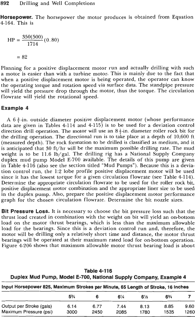
Table
4-116
Duplex Mud Pump, Model E-700, National Supply Company, Example
4
Input Horsepower
825,
Maximum
Strokes per Minute,
65
Length
of
Stroke,
16
Inches
Output
per Stroke
(gals) 6.14
6.77 7.44
8.13 8.85
9.60
Maximum
Pressure
(psi) 3000
2450 2085
1780 1535
1260
Downhole Motors
893
MAXIMUM RECOMMENDED BEARING LOAD
OFF
BOllOM BEARING LOAD
(1
000
LBS)
5
0
5
5
10
15
20
ON
BOTTOM BEARING LOAD
(1
000
LBS)
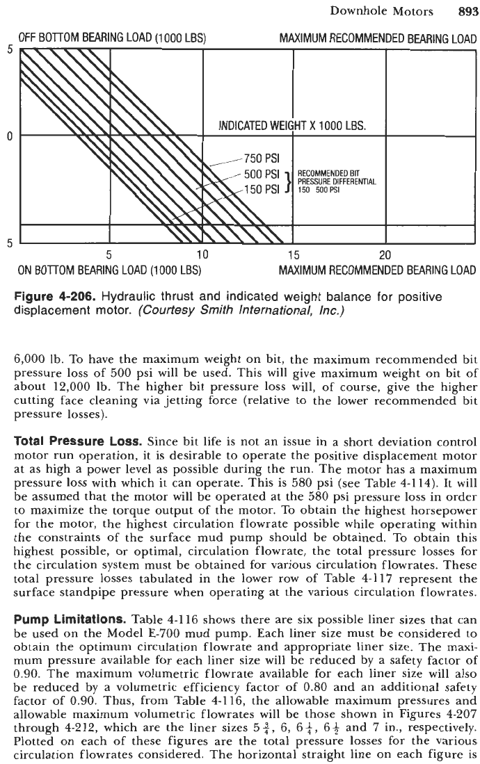
Figure
4-206.
Hydraulic thrust and indicated weight balance for positive
displacement motor.
(Courtesy Smith International, Inc.)
MAXIMUM RECOMMENDED BEARING LOAD
6,000 lb. To have the maximum weight on bit, the maximum recommended bit
pressure loss of 500 psi will be used. This will give maximum weight on bit
of
about 12,000 Ib. The higher bit pressure loss will, of course, give the higher
cutting face cleaning via jetting force (relative to the lower recommended bit
pressure losses).
Total Pressure
LOSS.
Since bit life is not an issue in a short deviation control
motor run operation, it is desirable to operate the positive displacement motor
at as high a power level as possible during the run. The motor has a maximum
pressure
loss
with which it can operate. This is 580 psi (see Table 4-114). It
will
be assumed that the motor will be operated at the 580 psi pressure loss in order
to maximize the torque output of the motor.
To
obtain the highest horsepower
for the motor, the highest circulation flowrate possible while operating within
the constraints of the surface mud pump should be obtained. To obtain this
highest possible, or optimal, circulation flowrate, the total pressure losses for
the circulation system must be obtained for various circulation flowrates. These
total pressure losses tabulated in the lower row of Table 4-1
17
represent the
surface standpipe pressure when operating at the various circulation flowrates.
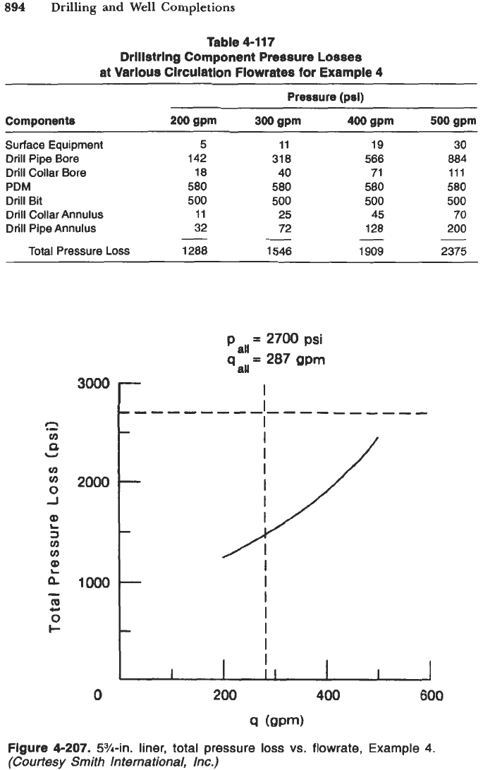
Pump Limitations.
Table 4-116 shows there are six possible liner sizes that can
be used on the Model E-700 mud pump. Each liner size must be considered to
obtain the optimum circulation flowrate and appropriate liner
size.
The
maxi-
mum pressure available for each liner size will be reduced by a safety factor
of
0.90. The maximum volumetric flowrate available for each liner size
will
also
be reduced by a volumetric efficiency factor of 0.80 and an additional safety
factor of 0.90. Thus, from Table 4-116, the allowable maximum pressures and
allowable maximum volumetric flowrates will be those shown in Figures 4-207
through 4-212, which are the liner sizes 5+, 6, 6$,
64
and
7
in., respectively.
Plotted on each of these figures are the total pressure losses for the various
circulation flowrates considered. The horizontal straight line on each figure
is
894
Drilling
and
Well Completions
-
I
I
I
-------------------
-
-
-
,./
I
I
I
I
I
I
I
-
-
I
I
II
I
I
1
Table 4-117
Drlllstring Component Pressure
Losses
at Various Circulation Flowrates for Example 4
~~~
Pressure
(psi)
Surface Equipment
Drill Pipe
Bore
Drill Collar
Bore
PDM
Drill
Bit
Drill
Collar
Annulus
Drill Pipe Annulus
Total Pressure
Loss
5
142
18
580
500
11
32
1288
-
11
31 8
40
580
500
25
72
1546
-
19
566
71
580
500
45
128
1909
-
30
884
111
580
500
70
200
2375
3000
c2
cn
P
U
u)
0
J
u,
2000
L
L
a
1000
7
cn
cn
-
(D
0
+
U
0
4
(QPm)
Flgure 4-207.
5%-in. liner,
total pressure
loss
vs.
flowrate,
Example
4.
(Courtesy Smith International, Inc.)