Lyons W.C. (ed.). Standard handbook of petroleum and natural gas engineering.2001- Volume 1
Подождите немного. Документ загружается.

MWD and LWD
905
Figure
4.
KEY
"
\
MAGNETOMETER
Y'
Y
C
H
VlETER
18.
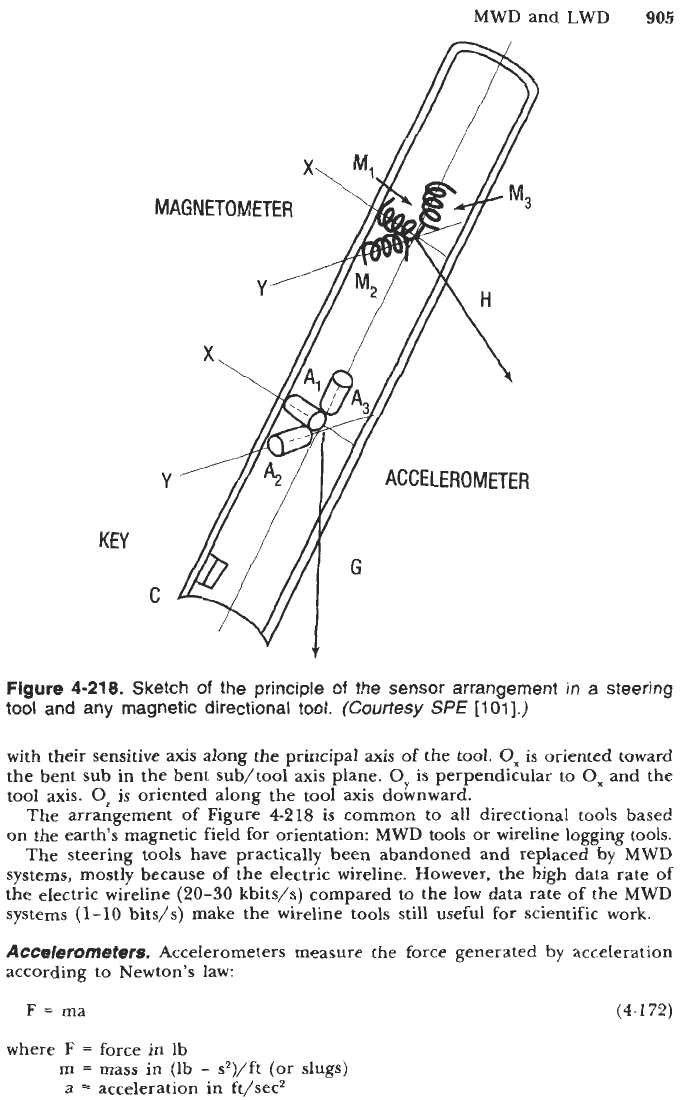
Sketch
of
the principle
of
the sensor arrangemer
tool
and
any
magnetic directional
tool.
(Courtesy
SPE
[loll.)
in
a
steering
with their sensitive
axis
along the principal
axis
of
the
tool.
Ox
is oriented toward
the bent
sub
in the bent sub/tool axis plane.
Oy
is
perpendicular to
Ox
and the
tool axis.
Oz
is oriented along the tool axis downward.
The arrangement
of
Figure
4-218
is
common
to
all directional
tools
based
on
the earths magnetic field for orientation: MWD tools
or
wireline logging tools.
The steering tools have practically been abandoned and replaced by
MWD
systems, mostly because
of
the electric wireline. However, the high data rate
of
the electric wireline
(20-30
kbits/s) compared to the low data rate
of
the MWD
systems
(1-10
bits/s) make the wireline tools still useful
for
scientific work.
Accelerometers.
Accelerometers measure the force generated
by
acceleration
according to Newton's law:
F
=
ma
(4-1
72)
where
F
=
force in lb
m
=
mass in
(Ib
-
s2)/ft
(or
slugs)
a
=
acceleration in ft/sec2
906
Drilling and Well Completions
If the acceleration is variable, as in sinusoidal movement, piezoelectric systems
are ideal. In case of a constant acceleration, and hence a force that is also
constant, strain gages may be employed. For petroleum applications in boreholes,
however, it is better to use servo-controlled accelerometers. Reverse pendular
accelerometers and “single-axis” accelerometers are available.
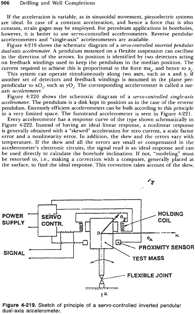
Figure
4-2
19
shows the schematic diagram
of
a
servo-controlled inverted pendular
dual-axis accelerometer.
A
pendulum mounted on a flexible suspension can oscillate
in the direction of the arrows. Its position is identified by two detectors acting
on feedback windings used to keep the pendulum in the median position. The
current required to achieve this is proportional to the force max, and hence to ax.
This system can operate simultaneously along two axes, such as x and y, if
another set of detectors and feedback windings is mounted in the plane per-
pendicular to xOp, such as
yoz.
The corresponding accelerometer is called a
two-
axis accelerometer.
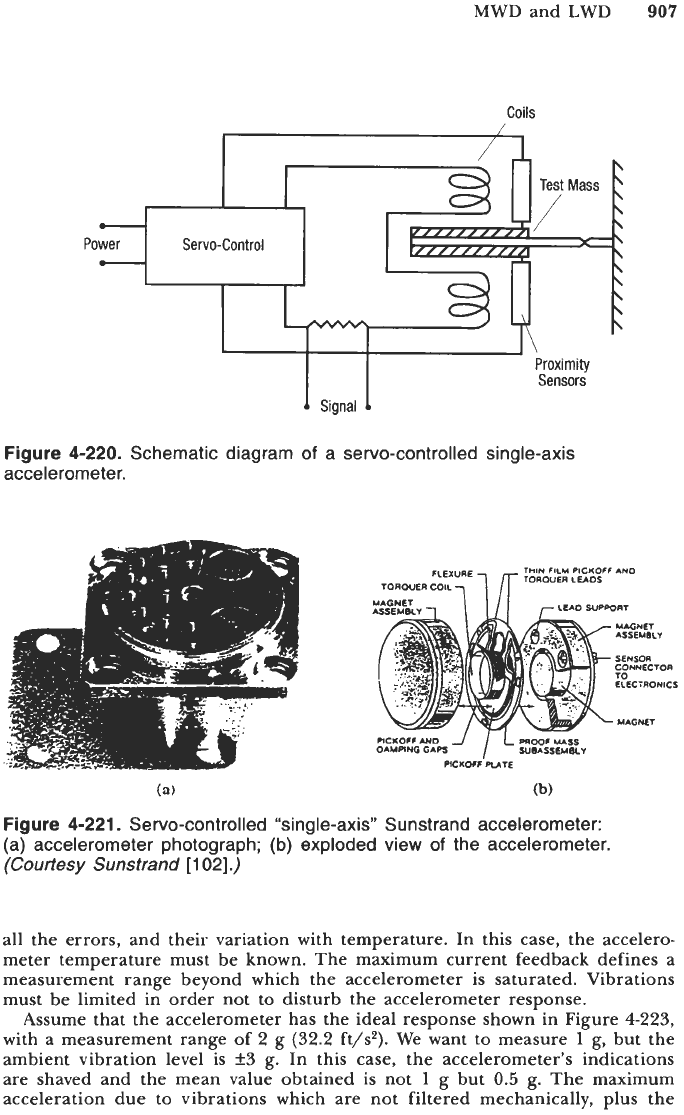
Figure
4-220
shows the schematic diagram
of
a
servo-controlled single-axis
accelerometer.
The pendulum is a disk kept in position as in the case of the reverse
pendulum. Extremely efficient accelerometers can be built according
to
this principle
in a very limited space. The Sunstrand accelerometer is seen in Figure
4-221.
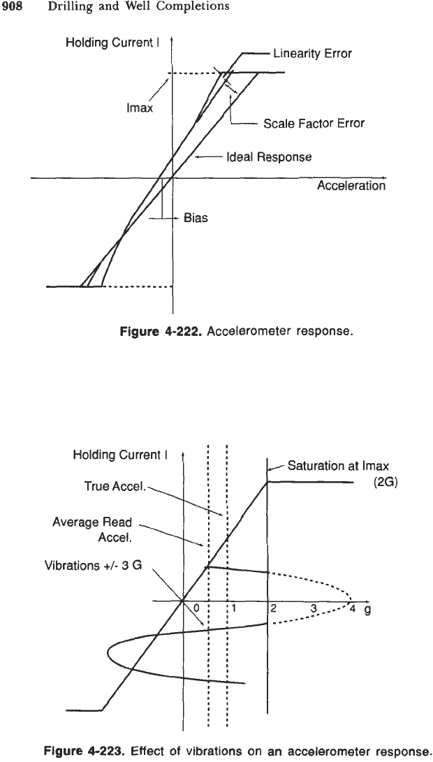
Every accelerometer has a response curve
of
the type shown schematically in
Figure
4-222.
Instead
of
having an ideal linear response, a nonlinear response
is generally obtained with a “skewed” acceleration for zero current, a scale factor
error and a nonlinearity error. In addition, the skew and the errors vary with
temperature. If the skew and all the errors are small or compensated in the
accelerometer’s electronic circuits, the signal read is an ideal response and can
be used directly to calculate the borehole inclination. If not, “modeling” must
be resorted to, i.e., making a correction with a computer, generally placed at
the surface, to find the ideal response. This correction takes account of the skew,
POWER
SUPPLY
SIGNAL
ICONTR.
%rl
A-l
HOLDING
COIL
--L
x
n”OXIMI’W
SENSOR
L’
-1
1
dk
‘TESTMASS
,
ky
FLEXIBLE
JOINT
,...,
,,,-*.
,*.*.
I=
Figure
4-219.
Sketch
of
principle
of
a servo-controlled inverted pendular
dual-axis accelerometer.
MWD and LWD
907
Coils
Po
Figure
4-220.
Schematic diagram
of
a servo-controlled single-axis
accelerometer.
THIN
FILM
PICKOFF
AN0
TOROUER
LUOS
ELECiRONlCS
DAMPING
GAPS
PICKOFF PUIE
(a)
(b)
Figure
4-221.
Servo-controlled “single-axis” Sunstrand accelerometer:
(a) accelerometer photograph;
(b)
exploded view
of
the accelerometer.
(Courtesy
Sunstrand
[
1
021.)
all the errors, and their variation with temperature. In this case, the accelero-
meter temperature must be known. The maximum current feedback defines a
measurement range beyond which the accelerometer is saturated. Vibrations
must be limited in order not to disturb the accelerometer response.
Assume that the accelerometer has the ideal response shown in Figure
4-223,
with a measurement range
of
2
g
(32.2
ft/s2). We want to measure
1
g, but the
ambient vibration level is
f3
g. In this case, the accelerometer’s indications
are shaved and the mean value obtained is not
1
g but
0.5
g. The maximum
acceleration due to vibrations which are not filtered mechanically,
plus
the
908
Drilling
and
Well Completions
Holding Current
I
Scale Factor Error
c
Acceleration
Figure
4-222.
Accelerometer response.
Figure
4-223.
Effect
of
vibrations on an accelerometer response.
MWD
and
LWD
909
continuous component to be measured, must be less than the instrument’s
measurement range.
These instruments serve to measure the earth’s gravitational field with a
maximum value of
1
g. The typical values of the characteristics are:
scale factor,
3
mA/g
resolution, g
skew, g
service temperature,
-55
to
+15OoC
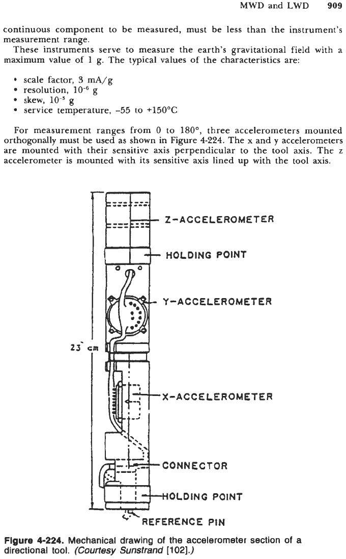
For measurement ranges from
0
to
180°,
three accelerometers mounted
orthogonally must be used as shown in Figure
4-224.
The x and
y
accelerometers
are mounted with their sensitive axis perpendicular to the tool axis. The
z
accelerometer is mounted with its sensitive axis lined up with the tool axis.
2-ACCELEROMETER
HOLDING POlN
T
Y-ACCELEROMETER
X-ACCEtEROMETER
CONNECTOR
OLDlNG
POINT
FERENCE
PIN
Figure
4-224.
Mechanical drawing
of
the accelerometer section
of
a
directional tool.
(Courtesy
Sunstrand
[102].)
910
Drilling and Well Completions
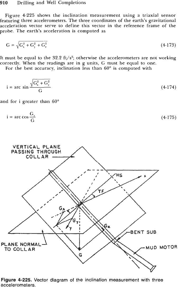
Figure
4-225
shows the inclination measurement using a triaxial sensor
featuring three accelerometers.
The
three coordinates
of
the earth's gravitational
acceleration vector serve to define this vector in the reference frame of the
probe. The earth's acceleration is computed as
G=,/G;+G;+G;
(4-173)
It must be equal to the
32.2
ft/s2; otherwise the accelerometers are not working
correctly. When the readings are in g units,
G
must be equal to one.
For the best accuracy, inclination less than
60"
is computed with
dG;
+
G:
G
i
=
arc sin
and for i greater than
60"
G
i
=
arc cos2
G
(4-174)
(4-175)
PLANE
NORMAL
TO
COLLAR
Figure
4-225.
Vector diagram
of
the inclination measurement with three
accelerometers.
TOR
MWD and LWD
911
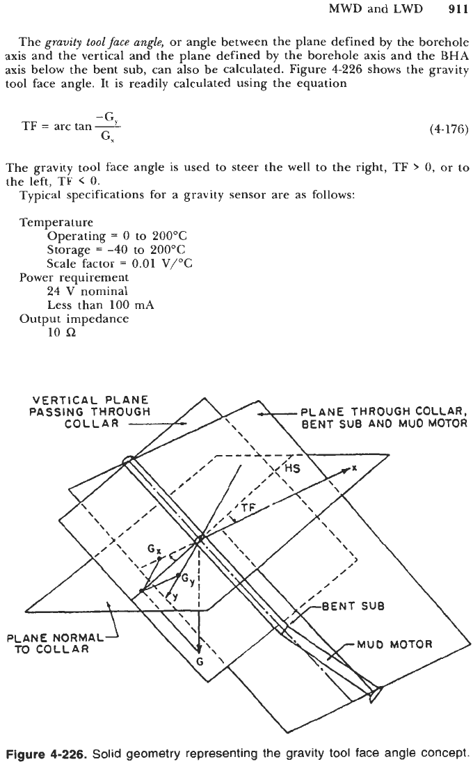
The
gravity tool face angle,
or angle between the plane defined by the borehole
axis and the vertical and the plane defined by the borehole axis and the BHA
axis below the bent sub, can also be calculated. Figure
4-226
shows the gravity
tool face angle. It is readily calculated using the equation
-G
TF
=
arc tan
2
G,
(4-1
76)
The gravity tool face angle is used to steer the well to the right, TF
>
0,
or
to
the left, TF
<
0.
Typical specifications for a gravity sensor are as follows:
Temperature
Operating
=
0
to
200°C
Storage
=
-40
to
200°C
Scale factor
=
0.01
V/OC
Power requirement
24
V
nominal
Less than
100
mA
Output impedance
10
sz
Figure
4-226.
Solid
geometry representing the gravity
tool
face angle concept.
912
Drilling and Well Completions
Mechanical characteristics
Length
=
60
cm (24 in.)
Diameter
=
3.75 cm (1.5 in.)
Mass
=
2 kg
(4
lb)
Alignment
=
f0.4”
Scale factor
=
5 V/g fl% (g
=
32.2 ft/s2)
Bias
=
f0.005 g
@
25°C
Linearity
=
fO.l% full scale
Environmental characteristics
Vibrations
=
1.5 cm p-p (peak-to-peak), 10 to 50 Hz
50g,
50
to 2000 Hz
Shock
=
2000 g,
0.5
ms, 0.5 sine
Electrical characteristics
Magnetometers.
Magnetometers used in the steering tools
or
MWD tools are
of the flux-gate type.
The basic definition of a magnetometer is a device that detects magnetic
fields and measures their magnitude and/or direction. One of the simplest types
of magnetometers is the magnetic compass. However, due to its damping
problems more intricate designs of magnetometers have been developed. The
“Hall effect” magnetometer is the least sensitive. The “flux-gate” magnetometer
concept is based on the magnetic saturation of an iron alloy core.
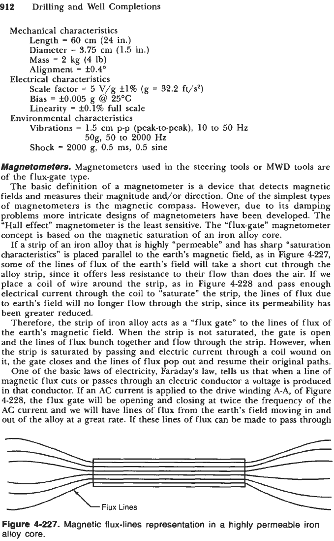
If a strip
of
an iron alloy that is highly “permeable” and has sharp “saturation
characteristics” is placed parallel to the earth’s magnetic field, as in Figure 4227,
some of the lines of flux of the earth’s field will take a short cut through the
alloy strip, since it offers less resistance to their flow than does the air. If we
place a coil of wire around the strip, as in Figure 4-228 and pass enough
electrical current through the coil to “saturate” the strip, the lines of flux due
to earth’s field will no longer flow through the strip, since its permeability has
been greater reduced.
Therefore, the strip of iron alloy acts as a “flux gate” to the lines of flux of
the earth’s magnetic field. When the strip is not saturated, the gate is open
and the lines of flux bunch together and flow through the strip. However, when
the strip is saturated by passing and electric current through a coil wound on
it, the gate closes and the lines of flux pop out and resume their original paths.
One of the basic laws of electricity, Faraday’s law, tells
us
that when a line of
magnetic flux cuts or passes through an electric conductor a voltage is produced
in that conductor. If an AC current is applied to the drive winding A-A, of Figure
4-228, the flux gate will be opening and closing at twice the frequency of the
AC current and we will have lines of flux from the earth’s field moving in and
out of the alloy at a great rate. If these lines of flux can be made to pass through
Flux
Lines
Figure
4-227.
Magnetic flux-lines representation in a highly permeable iron
alloy core.
MWD and LWD
913
g
A
DRIVE
WINDING
\
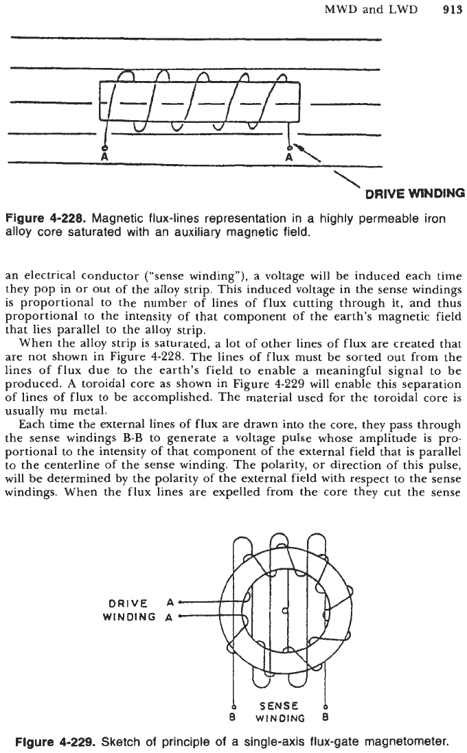
Figure
4-228.
Magnetic flux-lines representation in a highly permeable iron
alloy core saturated with an auxiliary magnetic field.
an electrical conductor (“sense winding”), a voltage will be induced each time
they pop in or out of the alloy strip. This induced voltage in the sense windings
is
proportional to the number of lines of flux cutting through it, and thus
proportional to the intensity of that component of the earth’s magnetic field
that lies parallel to the alloy strip.
When the alloy strip is saturated, a lot of other lines of flux are created that
are not shown in Figure
4-228.
The lines of flux must be sorted out from the
lines of flux due to the earth’s field to enable a meaningful signal to be
produced.
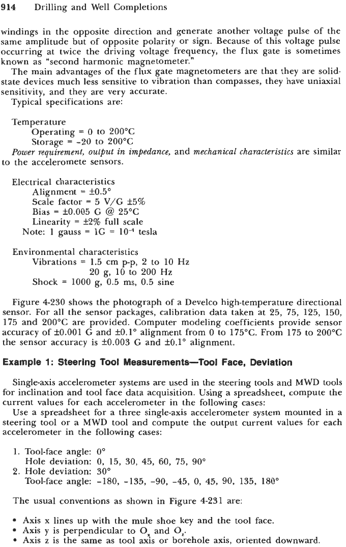
A
toroidal core as shown in Figure
4-229
will enable this separation
of lines of flux to be accomplished. The material used for the toroidal core is
usually mu metal.
Each time the external lines of flux are drawn into the core, they pass through
the sense windings
B-B
to generate a voltage pulse whose amplitude is pro-
portional to the intensity of that component of the external field that is parallel
to the centerline of the sense winding. The polarity, or direction of this pulse,
will be determined by the polarity of the external field with respect to the sense
windings. When the flux lines are expelled from the core they cut the sense
DRIVE
WlNOlNG
A
A
b
SENSE
0
WINDING
8
Figure
4-229.
Sketch of principle
of
a single-axis flux-gate magnetometer.
914
Drilling and Well Completions
windings in the opposite direction and generate another voltage pulse of the
same amplitude but of opposite polarity or sign. Because of this voltage pulse
occurring at twice the driving voltage frequency, the flux gate is sometimes
known as "second harmonic magnetometer."
The main advantages of the flux gate magnetometers are that they are solid-
state devices much less sensitive to vibration than compasses, they have uniaxial
sensitivity, and they are very accurate.
Typical specifications are:
Temperature
Operating
=
0
to
200°C
Storage
=
-20 to 200°C
Power requirement, output in impedance,
and
mechanical characteristics
are similar
to the acceleromete sensors.
Electrical characteristics
Alignment
=
f0.5"
Scale factor
=
5 V/G k5%
Bias
=
k0.005
G
@
25°C
Linearity
=
f2% full scale
Note: 1 gauss
=
1G
=
tesla
Environmental characteristics
Vibrations
=
1.5 cm p-p, 2 to 10 Hz
20 g, 10 to 200 Hz
Shock
=
1000 g, 0.5 ms, 0.5 sine
Figure 4-230 shows the photograph of a Develco high-temperature directional
sensor. For all the sensor packages, calibration data taken at 25, 75, 125, 150,
175 and 200°C are provided. Computer modeling coefficients provide sensor
accuracy of fO.OO1 G and fO.1" alignment from
0
to 175°C. From 175 to 200°C
the sensor accuracy is f0.003 G and f0.1" alignment.
Example
1
:
Steering Tool Measurements-Tool Face, Deviation
Single-axis accelerometer systems are used in the steering tools and MWD tools
for inclination and tool face data acquisition. Using a spreadsheet, compute the
current values for each accelerometer in the following cases:
Use
a
spreadsheet for a three single-axis accelerometer system mounted in a
steering tool or a MWD tool and compute the output current values for each
accelerometer in the following cases:
1. Tool-face angle:
0"
Hole deviation:
0,
15, 30, 45,
60,
75,
90"
2. Hole deviation: 30"
Tool-face angle: -180, -135,
-90,
-45,
0,
45,
90,
135, 180"
The usual conventions as shown in Figure 4-231 are:
Axis x lines up with the mule shoe key and the tool face.
Axis
y
is perpendicular to
Ox
and
Oz.
Axis
z
is the same as tool axis
or
borehole axis, oriented downward.