Lyons W.C. (ed.). Standard handbook of petroleum and natural gas engineering.2001- Volume 1
Подождите немного. Документ загружается.

MWD
and
LWD
965
(4-200)
where
Rgem
=
gas cut mud resistivity in
R
m
Rrn
=
gas free mud resistivity in
R
m
f,
=
volumetric gas content (fraction)
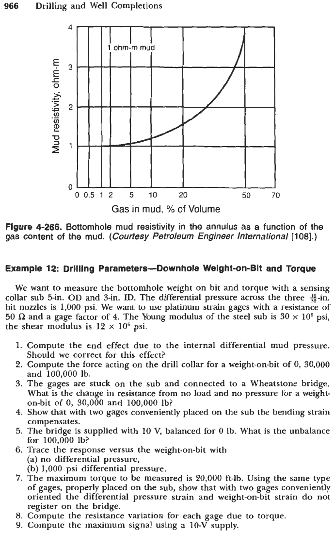
The variation is independent of the mud weight, pressure,
or
temperature,
but is sensitive to fluids other than gas, such as oil
or
saltwater. Figure
4-266
shows the resistivity variations for a 1-Rem mud. If we assume that a change
of
10%
can be detected, then the alarm could be given again for a free gas
or
oil volumetric concentration of
2
to 5%.
Mud
Temperature.
One can attempt
to
calculate the variation of the tempera-
ture of the mud when it mixes with a gas stream cooled by expansion.
Calculations were made with a 500-gal/min mud flowrate, an expansion from
10,500 to
10,000
psi with an 18-lb/gal mud and also an expansion from 5,500
to
5,000
psi with a 9-lb/gal mud. The temperature decrease of the mud was a
few
OF
up to 50% gas by volume in the mud.
Temperature measurements do not seem to be good gas indicators.
Mud acoustic attenuation and annulus noise level are being investigated. It
is
expected that attenuation would be very sensitive to free gas concentration.
18
16
-
m
14
0
x
c.
.-
v)
-0
-0
g
12
r'
10
8
6
-
9
Ib/gal, 5,000-psi water-base
mud
-
- -
-
18
Ib/gal, 10,000-psi water-base
mud
-
--
9
Ibigal, 5,000-psi oil-base
mud
-----.
18
Iblaal.
10,00O-~si
oil-base
mud
Gas
in
mud,
%
of
Volume
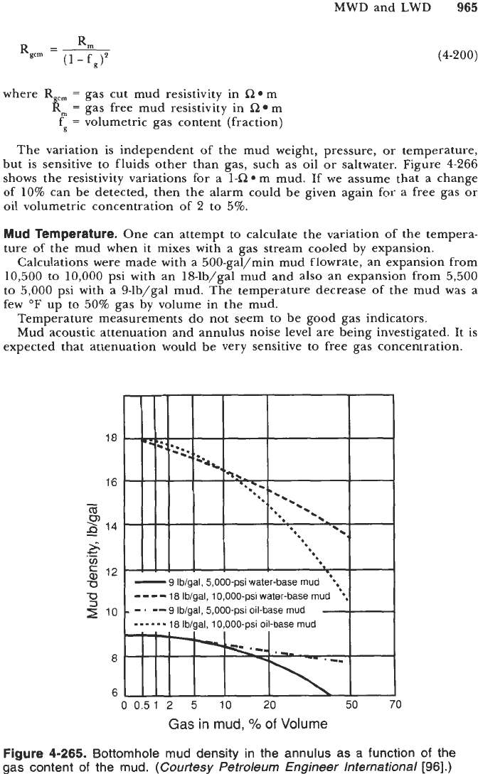
Figure
4-265.
Bottornhole mud density in the annulus as
a
function of the
gas content of the mud.
(Courtesy Petroleum Engineer lnternational
[96].)
966
Drilling and Well Completions
4
€3
E
0
0
0
0.5
1
2
5
10
20
50
70
Gas
in
mud,
o/o
of
Volume
Figure 4-266.
Bottomhole mud resistivity in the annulus as
a
function
of
the
gas content of the mud.
(Courtesy
Petroleum Engineer lnternational
[108].)
Example 12: Drilling Parameters-Downhole Weight-on-Bit and Torque
We want
to
measure the bottomhole weight on bit and torque with
a
sensing
collar sub 5-in.
OD
and 3-in. ID. The differential pressure across the three %-in.
bit nozzles is
1,000
psi. We want
to
use platinum strain gages with a resistance of
50
a
and a gage factor of
4.
The Young modulus of the steel sub is 30
x
lo6
psi,
the shear modulus is
12
x
lo6
psi.
1.
Compute the end effect due
to
the internal differential mud pressure.
Should we correct for this effect?
2.
Compute the force acting on the drill collar for a weight-on-bit of
0,
30,000
and
100,000
lb.
3. The gages are stuck on the sub and connected to a Wheatstone bridge.
What is the change in resistance from no load and no pressure for a weight-
on-bit of
0,
30,000 and
100,000
lb?
4.
Show that with two gages conveniently placed on the sub the bending strain
compensates.
5.
The bridge is supplied with
10
V,
balanced for
0
lb. What is the unbalance
for
100,000
lb?
6.
Trace the response versus the weight-on-bit with
(a) no differential pressure,
(b)
1,000
psi differential pressure.
7.
The maximum torque to be measured is
20,000
ft-lb. Using the same type
of gages, properly placed on the sub, show that with two gages conveniently
oriented the differential pressure strain and weight-on-bit strain do not
register on the bridge.
8.
Compute the resistance variation for each gage due to torque.
9.
Compute the maximum signal using a
10-V
supply.
MWD
and
LWD
967
Gage response
to
axial load is
(F0R.L)
AR
=
(E
A)
where
R
=
gage resistance in
R
AR
=
resistance variation in
R
F
=
gage factor
L
=
load in Ib
E
=
Young
modulus
A
=
sub cross-section or area in in.2
Gage response to torque
is
(T
F.
R. R")
G
K
(R:
-
Rf
)
AR
=
f
(4-20
1)
(4-202)
where
T
=
torque in in*lb
F
=
gage factor
R
=
gage resistance in
L2
R<,
=
sub internal radius in in.
R,
=
sub external radius in in.
G
=
shear modulus
Solution
1.
7.070 lb; yes, we should correct for this effect.
2. 7,070 lb downward, 22,930 lb upward, 92,930 lb upward.
3.
-0.004, 0.012 and 0.049
R.
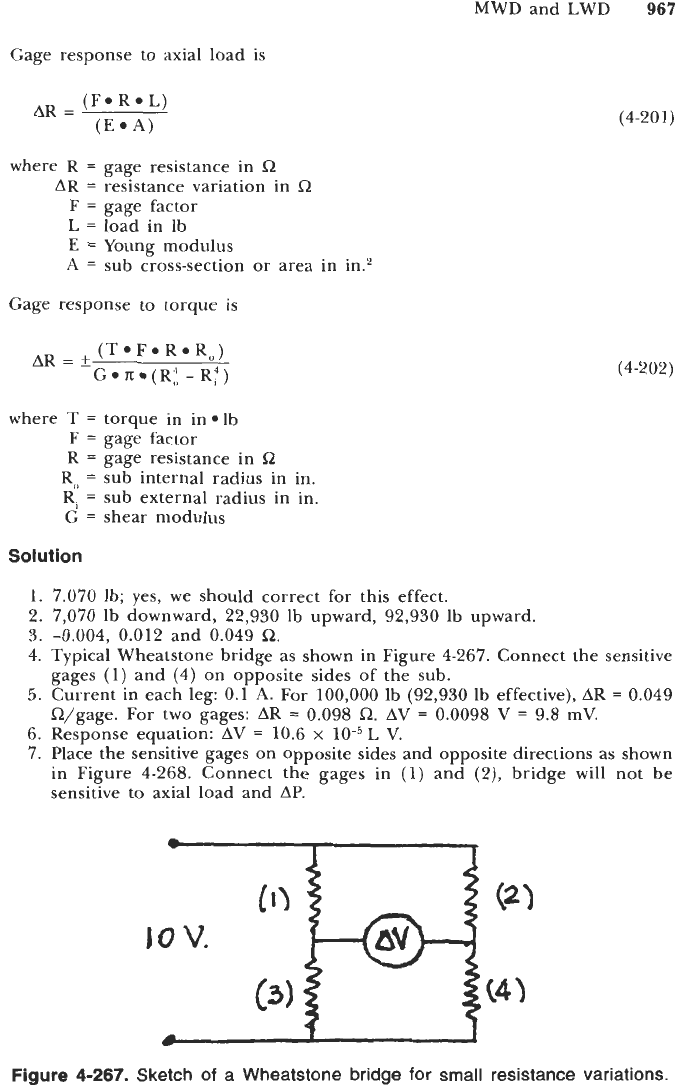
4. Typical Wheatstone bridge as shown in Figure 4-267. Connect the sensitive
5.
Current in each leg: 0.1
A.
For
100,000
lb (92,930 lb effective),
AR
=
0.049
6. Response equation:
AV
=
10.6
x
10-5L
V.
7.
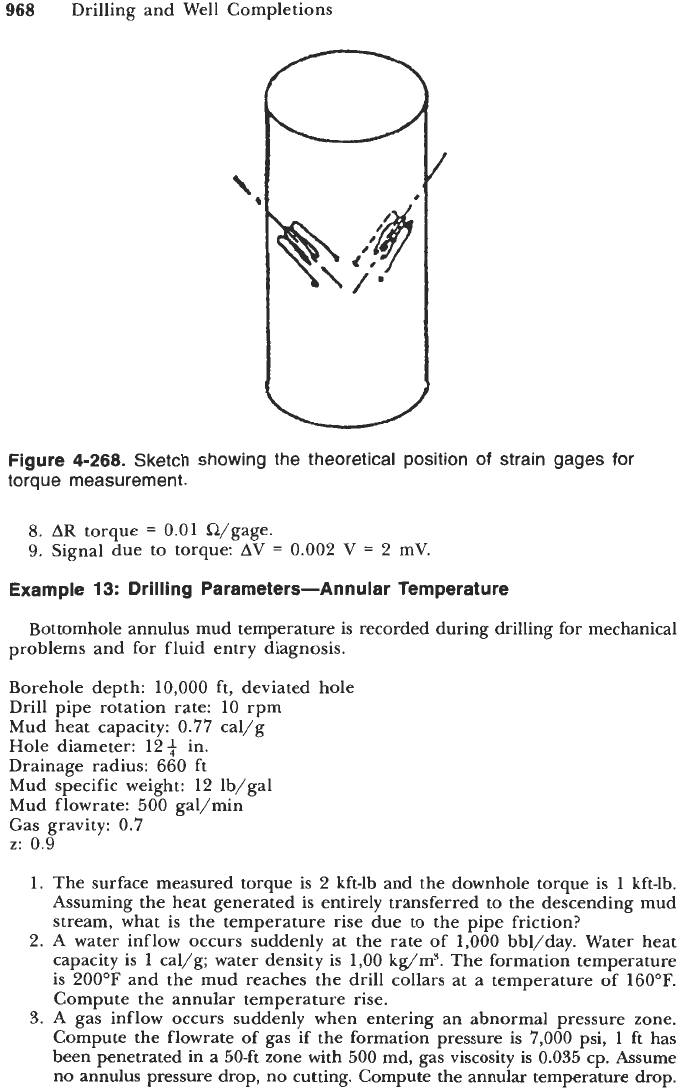
Place the sensitive gages on opposite sides and opposite directions as shown
in Figure 4-268. Connect the gages in
(1)
and
(Z),
bridge will not be
sensitive to axial load and
AP.
gages
(1)
and (4) on opposite sides
of
the sub.
R/gage. For two gages:
AR
=
0.098
R.
AV
=
0.0098
V
=
9.8
mV.
I
i
lo
V.
1
Figure
4-267.
Sketch
of
a Wheatstone bridge for
small
resistance variations.
968
Drilling and Well Completions
/
Figure
4-268.
Sketch showing the theoretical position of strain gages for
torque measurement.
8.
AR
torque
=
0.01
i&/gage.
9.
Signal due to torque: AV
=
0.002
V
=
2
mV.
Example
13:
Drilling Parameters-Annular Temperature
Bottomhole annulus mud temperature is recorded during drilling for mechanical
problems and for fluid entry diagnosis.
Borehole depth:
10,000
ft, deviated hole
Drill pipe rotation rate:
10
rpm
Mud heat capacity:
0.77
cal/g
Hole diameter:
12$
in.
Drainage radius:
660
ft
Mud specific weight:
12
lb/gal
Mud flowrate: 500 gal/min
Gas gravity:
0.7
z:
0.9
1.
The surface measured torque is
2
kft-lb and the downhole torque is
1
kft-lb.
Assuming the heat generated is entirely transferred to the descending mud
stream, what is the temperature rise due to the pipe friction?
2.
A
water inflow occurs suddenly at the rate of
1,000
bbl/day. Water heat
capacity is
1
cal/g; water density is
1,00
kg/m3. The formation temperature
is
200°F
and the mud reaches the drill collars at a temperature of
160°F.
Compute the annular temperature rise.
3.
A gas inflow occurs suddenly when entering an abnormal pressure zone.
Compute the flowrate of gas if the formation pressure is
7,000
psi,
1
ft has
been penetrated in a 50-ft zone with 500 md, gas viscosity is 0.035 cp. Assume
no annulus pressure drop, no cutting. Compute the annular temperature drop.
MWD and LWD
969
(4-203)
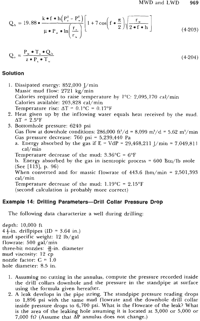
(4-204)
Solution
1.
Dissipated energy: 852,000 J/min
Massic mud flow: 2721 kg/min
Calories required to raise temperature by
IOC:
2,095,170 cal/min
Calories available: 203,828 cal/min
Temperature rise:
AT
=
0.1"C
=
0.17"F
AT
=
2.5"F
Gas flow at downhole conditions: 286,000 ft3/d
=
8,099 mg/d
=
5.62 m3/min
Gas pressure decrease: 760 psi
=
5,239,440 Pa
a. Energy absorbed by the gas if
E
=
VdP
=
29,468,211 J/min
=
7,049,811
Temperature decrease of the mud: 3.36"C
=
6°F
b. Energy absorbed by the gas in isentropic process
=
600 Btu/lb mole
(See [113], p. 96)
When converted and for massic flowrate of 443.6 lbm/min
=
2,501,393
cal/min
Temperature decrease of the mud: 1.19"C
=
2.15"F
(second calculation is probably more correct)
2. Heat given up by the inflowing water equals heat received by the mud.
3.
Bottomhole pressure: 6240 psi
cal/min
Example
14:
Drilling Parameters-Drill Collar Pressure Drop
The following data characterize a well during drilling:
depth: 10,000 ft
43-in. drillpipes
(ID
=
3.64 in.)
mud specific weight: 12 lb/gal
flowrate: 500 gal/min
three-bit nozzles: %-in. diameter
mud viscosity: 12 cp
nozzle factor:
C
=
1.0
hole diameter: 8.5 in.
1.
Assuming no cutting in the annulus, compute the pressure recorded inside
the drill collars downhole and the pressure in the standpipe at surface
using the formula given hereafter.
2. A leak develops in the pipe string. The standpipe pressure reading drops
to
1,896 psi with the same mud flowrate and the downhole drill collar
inside pressure drops
to
6,700 psi. What is the flowrate of the leak? What
is the area of the leaking hole assuming it is located at
3,000
or 5,000 or
7,000
ft? (Assume that
AP
annulus does not change.)
970
Drilling and Well Completions
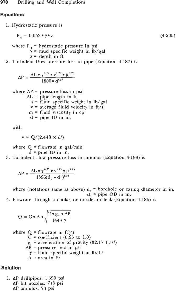
Equations
1.
Hydrostatic pressure is
P,
=
0.052
y*
z
where
P,
=
hydrostatic pressure in psi
y
=
mud specific weight in lb/gal
z
=
depth in ft
2.
Turbulent flow pressure loss in pipe (Equation
4-187)
is
(4-205)
where
AP
=
pressure loss in psi
AL
=
pipe length in
ft
y
=
fluid specific weight in Ib/gal
v
=
average fluid velocity in ft/s
m
=
fluid viscosity in cp
d
=
pipe
ID
in in.
with
v
=
w(2.448
x
d2)
where
Q
=
flowrate in gal/min
d
=
pipe
ID
in in.
3.
Turbulent flow pressure loss in annulus (Equation
4-188)
is
where (notations same as above) d,
=
borehole or casing diameter in in.
d,
=
pipe
OD
in in.
4.
Flowrate through a choke, or nozzle, or leak (Equation
4-186)
is
where
Q
=
flowrate in ft3/s
C
=
coefficient
(0.95
to
1.0)
g,
=
acceleration of gravity
(32.17
ft/s2)
AP
=
pressure loss in psi
y
=
fluid specific weight in Ib/ftJ
A
=
area in ft2
Solution
1.
AP
drillpipes:
1,590
psi
AP
bit nozzles:
718
psi
AP
annulus:
74
psi
MWD and LWD
971
Hydrostatic pressure:
6,240
psi
P inside DC:
7,032
psi
P standpipe:
2,382
psi
Pressure drop
in
DC due to leak
332
psi
New AP across nozzles:
386
psi
Q
through nozzles:
366.5
gal/min
Q
through drillpipes below leak:
366.5
gal/min
Q
through leak:
133.5
gal/min
2.
Total DP in pipe (friction plus leak):
1,436
psi
If leak at
3000
ft:
Pipe AP above leak:
477
psi
Pipe AP below leak:
646.5
psi
AP across leak:
312.5
psi
Leak cross-section:
0.24
in.2
If
leak at
5000
ft:
Pipe
AP
above leak:
745
psi
Pipe AP below leak:
462
psi
AP across leak:
229
psi
Leak cross-section:
0.28
in.'
If leak at
7,000
ft:
Pipe AP above leak:
1,272
psi
Pipe AP below leak:
277
psi
Sum is more than total AP
The leak must be above
7,000
ft
LWD
Technology
Logging while drilling has been attempted as early as
1939.
The first commer-
cial logs were run in the early
1980s.
First gamma ray logs were recorded
downhole and transmitted to the surface by mud pulses. Then came the resis-
tivity logs
of
various types that were also recorded downhole and/or transmitted
to
the surface,
Now,
neutron-density and Pe logs are also available.
Soon,
sonic
logs
will
be offered commercially.
Gamma Ray Logs
Gamma rays
of
various energy are emitted
by
potassium-40, thorium, uranium,
and the daughter products of these
two
last elements contained in the earth
formations surrounding the borehole. These elements occur primarily in shales.
The gamma rays reaching the borehole form a spectrum typical of each forma-
tion extending from a few keV to several MeV.
The gamma rays are detected today with sodium iodide crystals scintillation
counters. The counters,
6
to
12
in. long
(15
to
30
cm) are shock mounted and
housed in the drill collars. Several types of measurements can be made: total
gamma rays, direction-focused gamma rays, spectral gamma rays.
Total Gamma Rays.
Total gamma ray logs have been run on electric wireline
since
1940.
The sondes are rather small in diameter
(1.5
to
4
in. or
37
to
100
mm).
972
Drilling and Well Completions
The steel housing rarely exceeds 0.5 in. (12 mm) and a calibration is done in
terms of
API
units, arbitrary units defined in a standard calibration pit located
at the University of Houston.
The MWD total gamma ray tools cannot be calibrated in the standard pit, since
they are too large. Their calibration in
API
units is difficult because it varies with
the spectral content of the radiation. By spectral matching the MWD logs can be
made to closely resemble the wireline logs. The logs which were recorded by the
MWD companies in counts per second (cps) are now recorded in
API
units.
Another difference between the wireline logs and the MWD logs is the logging
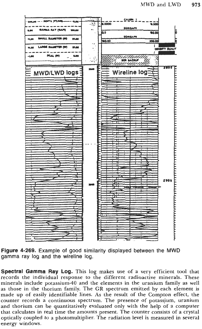
speed. With a wireline, the sonde is pulled out at a speed of 500 to 2,000 ft/min
(150 to 600 m/min). The time constant used to optimize the effect of the statis-
tical variations of the radioactivity emission, varied from 2 to
6
s.
Consequently,
the log values are somewhat distorted and inaccurate.
In MWD, the recording speed is the rate of penetration which rarely exceeds
120 to 150 ft/hr or 2 to
2.5
ft/min, two orders of magnitude less than the
logging speed. Counters can be made shorter and time constant longer (up to
30
s
or more). This results in a better accuracy and a better bed definition.
Figure 4-269 shows an example of comparison between an MWD gamma ray
log and the wireline log ran later.
To summarize, the total gamma ray measurements are used for real-time
correlation, lithology identification, depth marker and kick-off point selection.
Direction-Focused
Gamma
Rays.
It is important to keep the trajectory of
horizontal or nearly horizontal wells in the pay zone.
By
focusing the provenance
of the gamma rays it is possible to determine if a shale boundary is approached
from above or from below.
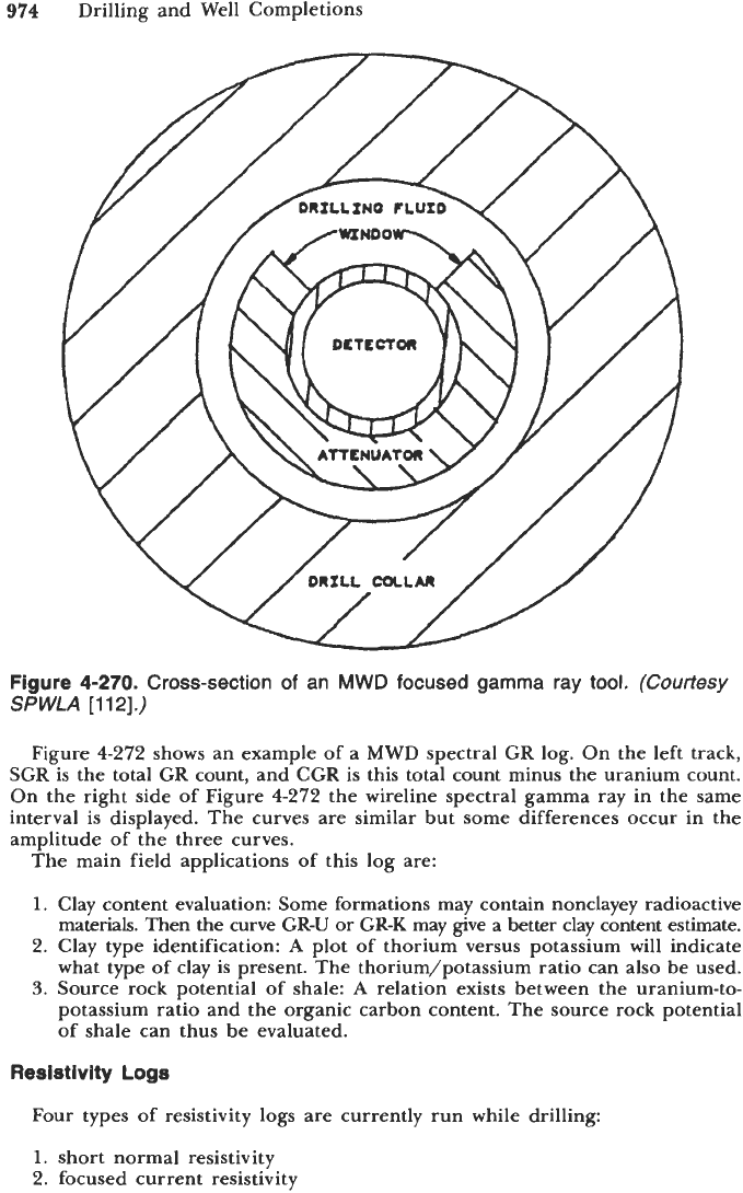
The tool shown in Figure 4-270 has its scintillation detector inserted in a
beryllium-copper housing, fairly transparent to gamma rays.
A
tungsten sleeve
surrounds the beryllium-copper housing, with a 90" slot or window running from
top to bottom. Figure 4-270 is a sketch of the tool cross-section. The center of
the window is keyed to the reference axis of the directional sensor. Consequently
the directional sensor indicates if the window is pointing up or down.
By rotating the tool, one can differentiate between the level of gamma rays
entering from the top and the lower part of the borehole.
A
sinusoidal response
is recorded which depends on the following:
distance from the bed boundary.
gamma ray intensity of the bed in which the tool is in
the contrast of radioactivity at the boundary.
the shielding efficiency of the tungsten sleeve.
An example of the log ran is a horizontal borehole as shown in Figure 4271.
The depths on the log are along the hole depths. Vertical depths are shown in
the higher part of the log with a representation of the true radioactivity of each
bed. The following observations can be made:
Approaching formation bed boundaries are detected by concurrent separation
and displacement of the high and low gamma counts. These are shown in
Figure 4271 at measured depth intervals (7970-7980 ft) and (8010-8020 ft).
Radioactive events occur in the measured depth interval (8,100-8,200 ft)
with no displacement of the low/high side gamma ray logs. The radioactive
events must be perpendicular to the gamma detector and could be indica-
tions of vertical natural fractures in the formation.
MWD and LWD
973
Figure
4-269.
Example
of
good similarity displayed between the
MWD
gamma ray log and the wireline log.
Spectral Gamma Ray Log.
This log makes use of a very efficient tool that
records the individual response to the different radioactive minerals. These
minerals include potassium-40 and the elements in the uranium family as well
as those in the thorium family. The
GR
spectrum emitted by each element is
made up of easily identifiable lines.
As
the result of the Compton effect, the
counter records a continuous spectrum. The presence
of
potassjum, uranium
and thorium can be quantitatively evaluated only with the help of a computer
that calculates in real time the amounts present. The counter consists of
a
crystal
optically coupled to a photomultiplier. The radiation level is measured in several
energy windows.
974
Drilling and Well Completions
Figure
4-270.
Cross-section
of
an
MWD
focused gamma
ray
tool.
(Courtesy
SPWLA
[112].)
Figure
4-272
shows an example of a MWD spectral GR log. On the left track,
SGR is the total GR count, and CGR is this total count minus the uranium count.
On the right side of Figure
4-272
the wireline spectral gamma ray in the same
interval is displayed. The curves are similar but some differences occur in the
amplitude of the three curves.
The main field applications
of
this log are:
1.
Clay content evaluation: Some formations may contain nonclayey radioactive
materials. Then the curve GR-U or GR-K may give a better clay content estimate.
2.
Clay type identification:
A
plot of thorium versus potassium will indicate
what type
of
clay is present. The thorium/potassium ratio can also be used.
3.
Source rock potential of shale:
A
relation exists between the uranium-to-
potassium ratio and the organic carbon content. The source rock potential
of shale can thus be evaluated.
Resistivity Logs
Four types of resistivity logs are currently run while drilling:
1.
short normal resistivity
2.
focused current resistivity