Lyons W.C. (ed.). Standard handbook of petroleum and natural gas engineering.2001- Volume 1
Подождите немного. Документ загружается.

MWD and LWD
985
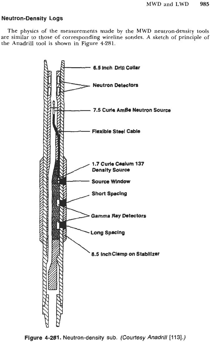
Neutron-Density Logs
The physics
of
the measurements made by the
MWD
neutron-density
tools
are similar to those
of
corresponding wireline sondes. A sketch
of
principle
of
the Anadrill tool is shown in Figure
4-281.
-
6.5
Inch
Drlfl
Collar
I
'W
1.7
Curie Cesium
137
Density
Source
[-
Source
Window
fle%lble Steel Cable
Short
Spacing
Gamma
Flay
Detectors
Long
Spacing
8.5
Inchclamp on Stabilizer
Figure
4-281.
Neutron-density sub.
(Courtesy
Anadrill
[113].)
986
Drilling and Well Completions
For the neutron porosity measurement, fast neutrons are emitted from a 7.5-
curie (Ci) americium-beryllium (Am-Be) source. The quantities of hydrogen in
the formation, in the form of water or oil-filled porosity as well as crystallization
water in the rock if any, primarily control the rate at which the neutrons slow
down to epithermal and thermal energies. Neutrons are detected in near- and
far-spacing detectors, located laterally above the source. Ratio processing is used
for borehole compensation.
The energy of the detected neutrons has an epithermal component because
a high percentage of the incoming thermal neutron flux is absorbed as it passes
through a 1 in.
of
drill collar steel. Furthermore, a wrap of cadmium under
the detector banks shields them from the thermal neutron arriving from the
inner mud channel. This mainly epithermal detection practically eliminates
adverse effects caused by thermal neutron absorbers in the borehole or in the
formation, such as boron.
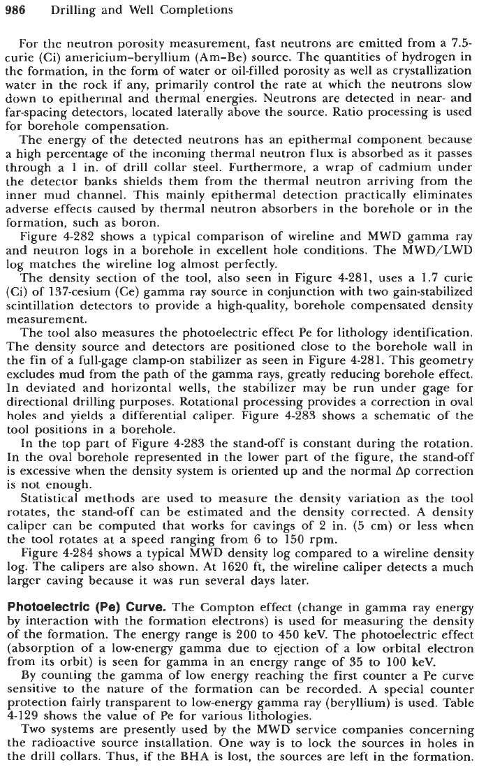
Figure 4-282 shows a typical comparison of wireline and MWD gamma ray
and neutron logs in a borehole in excellent hole conditions. The MWD/LWD
log matches the wireline log almost perfectly.
The density section of the tool, also seen in Figure 4-281, uses a
1.7
curie
(Ci) of 137-cesium (Ce) gamma ray source in conjunction with two gain-stabilized
scintillation detectors to provide a high-quality, borehole compensated density
measurement.
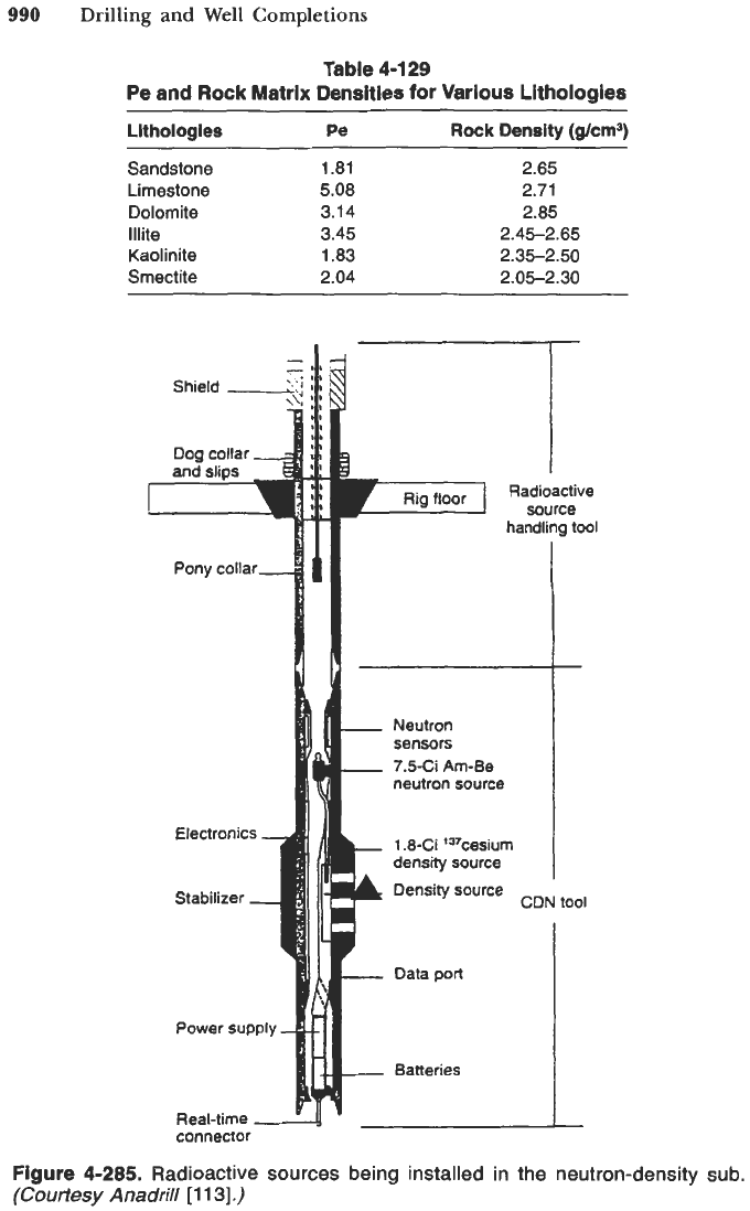
The tool also measures the photoelectric effect Pe for lithology identification.
The density source and detectors are positioned close to the borehole wall in
the fin of a full-gage clamp-on stabilizer as seen in Figure 4-281. This geometry
excludes mud from the path of the gamma rays, greatly reducing borehole effect.
In deviated and horizontal wells, the stabilizer may be run under gage for
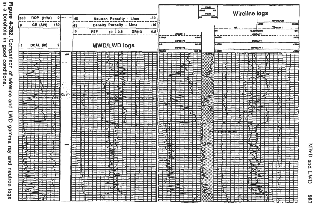
directional drilling purposes. Rotational processing provides a correction in oval
holes and yields a differential caliper. Figure 4-283 shows a schematic of the
tool positions in a borehole.
In the top part of Figure 4-283 the stand-off is constant during the rotation.
In the oval borehole represented in the lower part of the figure, the stand-off
is excessive when the density system is oriented up and the normal
Ap
correction
is not enough.
Statistical methods are used to measure the density variation as the tool
rotates, the stand-off can be estimated and the density corrected. A density
caliper can be computed that works for cavings of 2 in. (5 cm) or less when
the tool rotates at a speed ranging from 6 to 150 rpm.
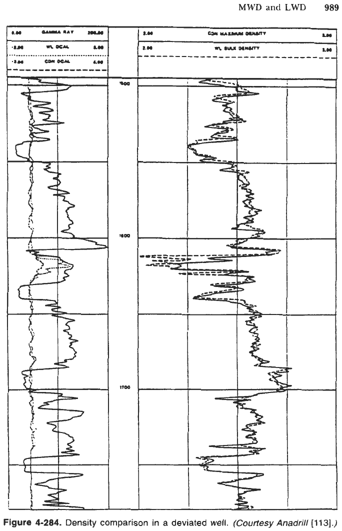
Figure 4-284 shows a typical MWD density log compared to a wireline density
log. The calipers are also shown. At 1620 ft, the wireline caliper detects a much
larger caving because
it
was run several days later.
Photoelectric
(Pe)
Curve.
The Compton effect (change in gamma ray energy
by interaction with the formation electrons) is used for measuring the density
of
the formation. The energy range is 200 to 450 keV. The photoelectric effect
(absorption of a low-energy gamma due to ejection of a low orbital electron
from its orbit) is seen for gamma in an energy range of 35 to 100 keV.
By counting the gamma of low energy reaching the first counter a Pe curve
sensitive to the nature of the formation can be recorded. A special counter
protection fairly transparent to low-energy gamma ray (beryllium) is used. Table
4-129 shows the value of Pe for various lithologies.
TWO systems are presently used by the MWD service companies concerning
the radioactive source installation. One way is to lock the sources in holes in
the drill collars. Thus, if the BHA is lost, the sources are left in the formation.
MWD
and
LWD
987
Figure
4-282.
Comparison
of
wireline and
LWD
gamma ray and neutron logs
in a borehole in good conditions.
988
Drilling and Well Completions
DE
CIRCULAR
BOREHOLE
iC
OR
L
.................................
............
............
~;il-I:/~>;iiii
..........
..........
..-..
I:::/
..
i!!!\<-
....
-
.....
......
......
........
.........
...........
...............
ENLARGED
BOREHOLE
i.
.....
J---
r-**u
.......
......
.'*..
........
..........
............
................
..........
..........
..........
..........
1FO(m*TIOII[:::
:::: :
::
..........
..........
..........
..........
..........
...............
.........
..........
.........
./pi
1.
:
.....
......
..
..
..
..
..
..
..
..
..
..
..
..
.,
.,
.,
................................
................................
-
COLLAR
WINOOW
IN
-
COLLAR
AND
STABILIZER
-
STANWFF
GRAVITY
Figure
4-283.
Schematic
of
the density
tool
position in a borehole.
(Courtesy
Anadrill
[
1
1
31
.)
Another way (Anadrill) is to use removable sources. Figure
4-285
shows the
sources being installed in the tool at surface. The two sources, neutrons and
gammas, are mounted on the same flexible shaft. They are moved from the
shield
to
the sub without being exposed. Furthermore, if the
BHA
becomes
stuck, they can be fished out with an overshot that connects to the fishing head
on top of the neutron source.
MWD
and
LWD
989
IY
u
mu
an
E
-
1.00
moo
l7C4
Figure
4-284.
Density comparison in
a
deviated
well.
(Courtesy
Anadri//[113].)
990
Drilling
and
Well Completions
Table
4-1
29
Pe and Rock Matrix Densities for Various Lithologies
Lithologies
Pe
Rock Density
(g/cm3)
Sandstone
1.81
2.65
Limestone
5.08 2.71
Dolomite
3.14 2.85
Illite
3.45 2.45-2.65
Kaolinite
1.83 2.35-2.50
Smectite
2.04 2.05-2.30
Rig
floor
I
Radioactive
source
handling tool
neutron source
Neutron
sensors
7.5-Ci Am-Be
connector
1
.&Ci
'37cesiu~
density source
Density source
ems:
.__,
-
Data
port
__
Batteries
CIUN
IOOI
I
Figure
4-285.
Radioactive sources being installed in the neutron-density sub.
(Courtesy
Anadrill
[i
131.)
MWD and LWD
991
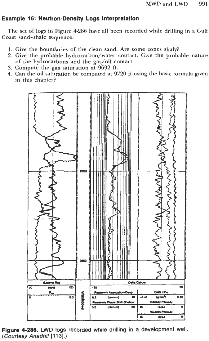
Example
16:
Neutron-Density
Logs
Interpretation
The set of logs in Figure
4-286
have all been recorded while drilling in a Gulf
Coast sand-shale sequence.
1.
Give the boundaries of the clean sand. Are some zones shaly?
2.
Give the probable hydrocarbon/water contact. Give the probable nature
3.
Compute the gas saturation at
9692
ft.
4.
Can the oil saturation be computed at
9720
ft using the basic formula given
of the hydrocarbons and the gas/oil contact.
in this chapter?
h.
0.1
Figure
4-286.
LWD logs
recorded while drilling in
a
development well.
(Courtesy
Anadrill
11131.)
992
Drilling and Well Completions
Solution
1.
Shaly sand. Cleanest parts: 9679 to 9696 and 9803 to 9808 ft.
2.
Hydrocarbon/water contact at 9750 ft with
Rwa
curve.
Oil
to
9696 ft. Gas
3. At 9692 ft,
0
=
30%,
Rt
=
8
Rem,
Rw
=
0.1
Clem,
Sw
=
3.3%,
Sg
=
6.7%.
4.
No,
shaly sand formula must be used.
above with neutron density.
Example
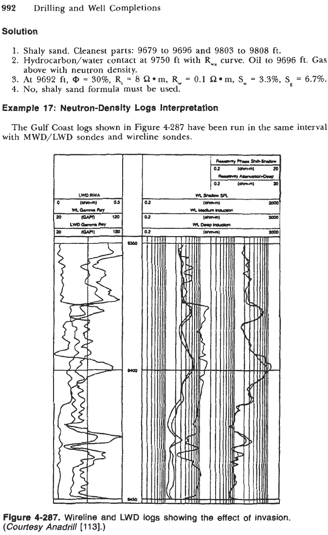
17:
Neutron-Density
Logs
Interpretation
with MWD/LWD sondes and wireline sondes.
The Gulf Coast logs shown in Figure 4-287 have been run in the same interval
t
Figure
4-287.
Wireline and LWD
logs
showing the effect
of
invasion.
(Courtesy
Anadrill
[
11
31.)
MWD and LWD
993
1.
2.
3.
4.
5.
Draw the lithology description in the depth column.
Looking at the
Rwa
curve, where is the hydrocarbon/water contact?
Do we have enough information to know if we have oil or gas?
What
is
the invasion diameter at
8397
ft using the wireline logs? What is
the invasion diameter using the MWD/LWD logs?
What
is
needed to compute the hydrocarbon saturation?
Solution
1.
2.
3.
4.
5.
Shale-sand sequence:
Top to
8,374
ft shale
8,374
to
8,425
ft sand
8,425
to
8,429
ft
8,429
to bottom sand
Hydrocarbon/water contact:
8,413
ft.
No,
we need the neutron and density curves.
According to chart in Figure
4-304,
di
=
40
in. with the wireline logs. The
dl
cannot be calculated with the MWD/LWD logs since we have only two
resistivity curves.
We need the porosity.
R,
is
given by
Rwa
in the lower sand. We also need
Rt.
shale break
Ultrasonic Caliper and Sonic Log while Drilling
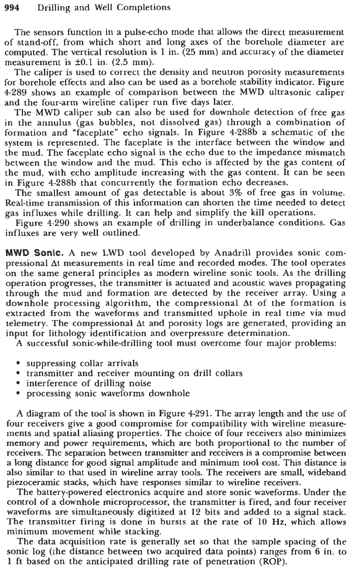
In the ultrasonic caliper sub, two ultrasonic sensors are mounted
180"
apart
on stabilizer blades as shown in Figure
4-288.
sensor
stabilizer
Time
after
firing
-
Clean
mud.
no
gas
-
Mud
with
gas
(b)
Figure
4-288.
MWD
ultrasonic caliper: (a) sensor in the stabilizer blades;
(b)
schematic
of
the echoes.
(Courtesy
Anadrill
[113].)
994
Drilling and Well Completions
The sensors function in a pulseecho mode that allows the direct measurement
of stand-off, from which short and long axes
of
the borehole diameter are
computed. The vertical resolution is
1
in.
(25
mm) and accuracy of the diameter
measurement is
fO.l
in.
(2.5
mm).
The caliper is used to correct the density and neutron porosity measurements
for borehole effects and also can be used as a borehole stability indicator. Figure
4-289 shows an example of comparison between the MWD ultrasonic caliper
and the four-arm wireline caliper run five days later.
The MWD caliper sub can also be used for downhole detection
of
free gas
in the annulus (gas bubbles, not dissolved gas) through a combination of
formation and “faceplate” echo signals. In Figure 4-288b a schematic of the
system is represented. The faceplate is the interface between the window and
the mud. The faceplate echo signal is the echo due to the impedance mismatch
between the window and the mud. This echo is affected by the gas content of
the mud, with echo amplitude increasing with the gas content. It can be seen
in Figure 4-288b that concurrently the formation echo decreases.
The smallest amount of gas detectable is about
3%
of free gas in volume.
Real-time transmission of this information can shorten the time needed to detect
gas influxes while drilling. It can help and simplify the kill operations.
Figure 4-290 shows an example of drilling in underbalance conditions. Gas
influxes are very well outlined.
MWD
Sonic.
A new LWD tool developed
by
Anadrill provides sonic com-
pressional At measurements in real time and recorded modes. The tool operates
on the same general principles as modern wireline sonic tools.
As
the drilling
operation progresses, the transmitter is actuated and acoustic waves propagating
through the mud and formation are detected by the receiver array. Using a
downhole processing algorithm, the compressional At of the formation is
extracted from the waveforms and transmitted uphole in real time via mud
telemetry. The compressional At and porosity logs are generated, providing an
input for lithology identification and overpressure determination.
A
successful sonic-while-drilling tool must overcome four major problems:
suppressing collar arrivals
transmitter and receiver mounting on drill collars
interference of drilling noise
processing sonic waveforms downhole
A
diagram of the tool is shown in Figure 4291. The array length and the use of
four receivers give a good compromise for compatibility with wireline measure-
ments and spatial aliasing properties. The choice of four receivers also minimizes
memory and power requirements, which are both proportional to the number of
receivers. The separation between trapmitter and receivers is a compromise between
a
long distance for good signal amplitude and minimum tool cost. This distance is
also similar to that used in wireline array tools. The receivers are small, wideband
piezoceramic stacks, which have responses similar to wireline receivers.
The battery-powered electronics acquire and store sonic waveforms. Under the
control of a downhole microprocessor, the transmitter is fired, and four receiver
waveforms are simultaneously digitized at
12
bits and added to a signal stack.
The transmitter firing is done in bursts at the rate of
10
Hz, which allows
minimum movement while stacking.
The data acquisition rate is generally set
so
that the sample spacing of the
sonic log (the distance between two acquired data points) ranges from
6
in. to
1
ft based on the anticipated drilling rate of penetration
(ROP).