Malcolm Barnes. Practical Variable Speed Drives and Power Electronics
Подождите немного. Документ загружается.

9
Special topics and new
developments
9.1 Soft-switching
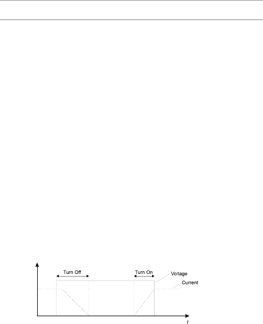
The present design of PWM voltage source inverters involves a constant DC link voltage
supply and semiconductor switching devices, with anti-parallel diodes, feeding an
inductive load. When device switching occurs, the other anti-parallel diode in the same
leg conducts and assures that full voltage is across the switching device. This gives it the
so-called clamped inductive load switching waveform, as shown in Figure 9.1. This leads
to the simultaneous large voltages and currents that give rise to high switching losses in
an inverter.
A new inverter topology, which is under investigation, gives either zero voltage or zero
current during switching, to reduce switching power loss to a very low level. This new
technique is called soft switching and should allow future semiconductor devices to be
switched at much higher frequencies, thereby giving better waveform control.
Figure 9.1:
Characteristic of clamped inductive load switching waveform
230 Practical Variable Speed Drives and Power Electronics
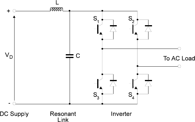
One of the possible designs for achieving this goal is the resonant link inverter, which is
shown for a single-phase case in Figure 9.2. The front-end is identical to a normal ‘hard
switched’ inverter, except for the series inductor and shunt capacitor between the DC bus
and the inverter stage.
The circuit is controlled as follows:
• Assume that the capacitor is momentarily discharged from the previous cycle
of inverter operation.
• All inverter switches are turned ON at zero voltage, applying zero volts to the
load and shorting out the capacitor. The inductor current then ramps up
through the switches.
• When the inductor current reaches an appropriate level, one switch in each leg
is opened (at zero voltage) to apply voltage to the load. The capacitor voltage
then rings up to a value exceeding the supply while the inductor current
decreases. The oscillation continues with capacitor voltage now decreasing.
• When the capacitor voltage decreases to zero, the anti-parallel diodes clamp
the capacitor voltage from going negative, in effect placing a short-circuit
across the capacitor and momentarily discharging it.
• The process is repeated.
Figure 9.2:
The topology of a single-phase resonant link ‘soft’ inverter
The supply across the inverter legs has the form of a series of pulses with the same
waveform as the capacitor voltage as shown in Figure 9.3. The inverter legs must switch
at one of the voltage zeros if the resonance is to be continued and low switching losses
are to be achieved.

Special topics and new developments 231
Figure 9.3:
Resonant link inverter waveform at inverter leg
This circuit does not have the ability to give pulses with continuous variation in pulse
width as with the conventional inverter. The output voltage must be controlled by discrete
pulse modulation rather than pulse width modulation. However, the resonance is at such a
high frequency (50–100 kHz) that this does not limit the smoothness of the output current
because the load inductance is very effective at filtering such a high frequency.
There are several other types of soft-switching circuits under investigation at present.
Some of them do not maintain continuous resonance but are controlled to resonate at a
desired moment of switching, which allows continuous pulse width modulation. This type
of design, called a quasi-resonant link inverter, is related to the force-commutation
circuits, except that operation is at much higher frequencies and is used with gate
controlled devices which can inherently be turned off. Other designs allow zero-current
rather than zero-voltage turn off.
One of the advantages of this type of switching is that it results in lower levels of RFI
because of the slower rates of rise of voltage and current.
Most of the potential designs share common problems.
• Resonance inherently causes higher voltages than that of the supply, which
places higher stresses on the power switches and the load. This can be
overcome with the addition of other switches and energy storage elements to
absorb excess energy.
• They require more complex control systems because the instant of switching
has to be varied with the load to maintain resonance. This control must be
implemented at about 20 times the switching frequency of a conventional
inverter. This requires fast controller hardware and software, such as a digital
signal processor.
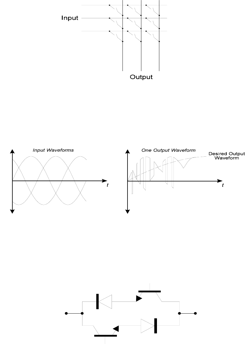
9.2 The matrix converter
All AC converter designs discussed in this book so far contain energy storage elements,
such as inductance and capacitance, as well as the semiconductor power switches. The
energy storage components result in extra losses, are bulky, and contribute to
unreliability. The matrix converter attempts to eliminate these storage devices.
232 Practical Variable Speed Drives and Power Electronics
Figure 9.4:
Matrix converter connection circuit
The concept is very simple, consisting of a matrix of switches joining each of the 3
input lines to an output line.
The output voltage waveform is made up of sections of the input as shown in the Figure
below. It has been demonstrated that the circuit can operate in all four quadrants with an
input line current of any desired power factor.
Figure 9.5:
The input and output voltage waveforms of the matrix converter
The main difficulty with the circuit is the requirement that the switches must be able to
conduct and block in both directions. Although it is possible to fabricate devices using
two power switches and two diodes, this is not an economical solution. There have been
attempts to produce a single chip ‘universal switch’ over the last three years with no
commercial success to date.
Figure 9.6:
Four-quadrant semiconductor switch

Appendix A
3UZUXVXUZKIZOUTmJOXKIZ
ZKSVKXGZ[XKYKTYOTM
A.1 Introduction
The main requirements for the protection of AC converters and AC induction motors has
been covered in considerable detail in Chapter 5: Protection of AC converters and motors.
This appendix covers some of the detail of the direct temperature sensing methods of
protecting electric motors.
A.2 Microtherm (thermostat)
A thermostat is a temperature dependent device that uses a bi-metallic strip to change the
position of a pair of contacts at the preset rated response temperature. When the
temperature exceeds a preset level, the contacts are used to switch an external control
device, such as a relay or contactor. To avoid ‘hunting’, some sort of hysteresis is usually
built into the device to ensure that the set and reset take place at different temperatures.
Microtherms, which are commonly used with electric motors, are miniature precision
thermostats, sufficiently small for direct insertion into the windings of a motor or
transformer to allow a close thermal association with the winding. The contacts, typically
rated at 2.5 amp at 240 volt, are capable of switching a contactor or relay directly. Several
microtherms are usually fitted into a motor, each designed to operate at a temperature
related to the design temperature of the area in the motor where it is placed. Typical
strategic locations are the windings, air ventilation path and bearings. The manufacturers
of DC motors tend to prefer Microtherms, while the manufacturers of AC motors tend to
prefer thermistors, which are described below.
Microtherms are usually used in groups of two, with one group having a rated reference
temperature of 5
o
C or 10
o
C lower than the other to provide a temperature pre-warning
alarm. The second group is used to trip the motor to prevent damage to the winding
insulation. On a motor of significant rating and thermal inertia, the pre-warning alarm
234 Practical Variable Speed Drives and Power Electronics
would give an operator several minutes to clear the process machine or rectify the
overload condition before the overload trip signal occurs.
In DC motors, two groups of microtherms are generally used. The mounting position of
the first group is usually at the hottest point of the hottest interpole, usually the one
carrying the armature current. This location provides protection for armature current
overload. The second group is usually located in the shunt field, providing protection for
both the shunt coil temperature and the general temperature within the motor.
In a modern shunt wound DC motor, the working temperature of the shunt winding is
very similar to that of the armature. Any loss or restriction of the cooling air, which is
difficult to monitor other than by direct measurement, will result in a fast rise in the
temperature of the field winding and will be detected by the microtherm.
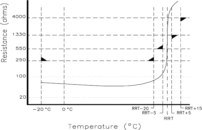
A.3 Thermistor sensors and thermistor protection relays
A thermistor is a small non-linear resistance sensor, which can be embedded within the
insulation of a motor winding, to provide a close thermal association with the winding. It
is made from a metal oxide or semiconductor material. The relationship between
resistance and temperature is non-linear and the resistance varies strongly with small
temperature changes around the set point.
By correct positioning, thermistors can be located close to the thermally critical areas,
or hot-spots, of the winding, where they closely track the copper temperature with a
certain time lag, depending on the size of the thermistors and how well they are installed
in the winding.
Thermistors are most easily inserted into the non-rotating parts of motors, such as the
stator winding in an AC motor or the interpole and field windings of a DC motor.
Figure A.1:
Characteristic curve of a PTC thermistor sensor to IEC TC2
RRT = Rated response temperature
IEC specified temperature/resistance limits are clearly marked
Motor protection – direct temperature sensing 235
The main advantages of thermistors are:
• Their small size allows them to be installed in direct contact with the stator
winding.
• Their low thermal inertia gives rapid and accurate response to winding
temperature changes.
• They measure temperature directly irrespective of how these temperatures are
initiated.
• They can be used to detect overload conditions in motors driven by frequency
converters.
The temperature coefficient can be positive (PTC – positive temperature coefficient),
where the resistance increases with temperature, or negative (NTC – negative temperature
coefficient), where the resistance decreases with temperature. The type most commonly
used in industry is the PTC thermistor, whose typical resistance characteristic is shown in
the curve below.
The resistance at normal temperatures is relatively low and remains nearly constant up
to the rated response temperature (RRT). As the RRT is approached and exceeded, the
gradient of the resistance increases sharply, giving the PTC thermistor a high sensitivity
to small changes of temperature. At the set point, a temperature rise of a few degrees
results in a large increase in resistance. The resistance is monitored by a thermistor
protection relay (TPR) and, when the sharp change in resistance is detected by the
thermistor protection relay (TPR), it operates a contact to initiate an alarm or to trip the
protected device.
Thermistor protection relays are required to trip reliably when the sensor resistance
rises above about 3 kΩ. They will also respond to an open circuit, either in the cable or
the thermistor sensor, thus providing fail-safe protection. Modern TPRs are also designed
to detect a thermistor sensor short circuit, when sensor resistance falls below about 50 Ω.
The specified operating levels are:
• Thermistor over-temperature protection according to IEC
− Response level = 3300 Ω ± 100 Ω
− Reset level = 1650 Ω ± 100 Ω
• Thermistor short-circuit protection according to IEC
− Response level ≤ 15 Ω
In AC variable speed drives, PTC thermistors are commonly used to protect the AC
squirrel cage motor fed from inverters. Many modern AC converters have a thermistor
protection unit built into the converter, avoiding the requirement for a separate thermistor
protection relay.
In DC motors, PTC thermistor sensors are increasingly used instead of microtherms,
which are described in the section above.
The rated response temperatures (RRT), which are commonly selected for the various
classes of insulation on electric motors, are summarized in the table in Figure A.2.

236 Practical Variable Speed Drives and Power Electronics
Insulation class Rated temp Alarm temp Trip temp
Class B
Class F
Class H
120
U
C
140
U
C
165
U
C
120
U
C
140
U
C
165
U
C
130
U
C
150
U
C
175
U
C
Figure A.2:
Typical temperature level settings used on rotating electrical machines
Due to the relatively slow transfer of heat to the sensors through the insulation medium,
PTC thermistors do not provide sufficiently fast protection for short circuits in motors or
transformers. Also, since they are usually located in the stator windings, they do not
provide adequate protection for rotor critical motors or for high inertia starting or stalled
rotor conditions. In these cases, to achieve complete protection, it is recommended that
PTC thermistors should be used in combination with electronic motor protection relays,
which monitor the primary current drawn by the motor.
The application of PTC thermistors as temperature sensors is only effective when:
• The rated response temperature (RRT) of the thermistor is correctly selected
for the class of insulation used on the winding.
• The thermistors are correctly located close to the thermally critical areas.
• There is a low thermal resistance between the winding and the PTC
thermistor. This depends on the electrical insulation between the winding and
the thermistor. Since thermistors need to be isolated from high voltages, it is
more difficult to achieve a low heat transfer resistance in HV motors, which
have greater insulation thickness.
Several thermistor sensors may be connected in series in a single sensor circuit,
provided that the total resistance at ambient temperatures does not exceed 1.5 kΩ. In
practice, and as recommended by IEC, up to six thermistor sensors can be connected in
series.
For a 3-phase AC motor, two thermistor sensors are usually provided in each of the 3
windings and connected in two series groups of three. One group can be used for alarm
and the other group for tripping of the motor. The alarm group is usually selected with a
lower rated response temperature (RRT); typically 5
o
C or 10
o
C lower than the tripping
group. If the operator takes no action, the tripping group is used to trip the motor directly
to prevent damage to the winding insulation. In many cases, users choose both groups to
have the same RRT. In this case, only one group of thermistors is used (one in each
phase) and these are then used for tripping the motor. This provides for one spare
thermistor in each phase.
The physical location of the thermistor sensors in an AC motor depends on the
construction of the motor, whether it has a cylindrical rotor or salient pole rotor, and
several other design and manufacturing variables. In some cases, the optimum location
may have to be determined from test experience.
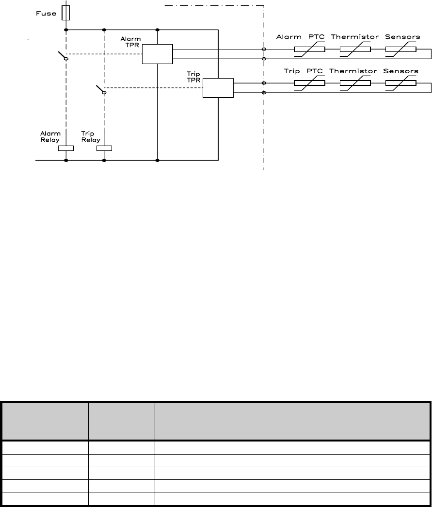
Thermistor protection relays (TPR) are designed for mounting inside a control cubicle
or motor control center, usually on standard terminal rails. The Figure A.3 shows a
typical connection of two thermistor protection relays, and their associated groups of
thermistor sensors.
For alarm and trip control of a 3-phase AC induction motor. The performance of
thermistor protection relays can be affected by external electrical interference, where
Motor protection – direct temperature sensing 237
voltages can be induced into the sensor cable. Consequently, cables between the
thermistor protection relay and the PTC thermistor sensors should be selected and
installed with a view to minimizing the effects of induced noise. Cables should be kept as
short as possible and should avoid running close to noisy or high voltage cables over long
distances.
Figure A.3:
Typical connection of thermistor protection relays
During testing, care should be taken not to megger across the thermistors as this can
damage them. The correct procedure is to connect all the thermistor leads together and to
apply the test voltage between them and earth or the phases.
Some practical recommendations for the type of cables that should be used are as
follows:
Distances
≤
20 m Standard parallel cable is acceptable
Distances
≥
20 m,
≤
100 m Twisted pair cable is necessary
Distances
≥
100 m Screened twisted pair (STP) cable is necessary
High level of interference Screened twisted pair (STP) cable is necessary
The screen should be earthed at one end only
For cable distances to the sensors of greater than 200 meters, the cross-sectional area of
the conductors should also be considered. The following are recommended:
Conductor
Cross-section
Maximum
Length
Type of Cable
0.5mm
200m Screened twisted pair (screen earthed at one end only)
0.75mm
300m Screened twisted pair (screen earthed at one end only)
1.0mm
400m Screened twisted pair (screen earthed at one end only)
1.5mm
600m Screened twisted pair (screen earthed at one end only)
2.5mm
1000m Screened twisted pair (screen earthed at one end only)
Figure A.4:
Recommended cable size to thermistor sensors
238 Practical Variable Speed Drives and Power Electronics
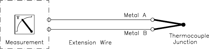
A.4 Thermocouple
Thermocouples consist of two lengths of dissimilar metals joined at one end to form a
junction. At the other open end, a small voltage is produced which is dependent on the
temperature at the junction. This is known as the peltier effect. As the temperature
changes, the developed thermionic voltage changes to give an indication of the
temperature.
Figure A.5:
Connections between a thermocouple sensor and its controller
There are several national standards, which specify the performance characteristics of
thermocouples, such as voltage/temperature, error limits and color-codes for connecting
wires. The most commonly used standards are listed below. These standards are generally
interchangeable in terms of their relationship between voltage and temperature.
•
ANSI M96.1 – American National Standards Institute (also known as the
NBS standard)
This is one of the most widely used standards for instrumentation. The ANSI
color-code always uses a red negative leg with a different color for the
positive leg indicating the type and temperature range of the thermocouple.
The overall sheath color is brown.
•
BS 1843 – British Standard
This standard uses a blue negative leg color-code, with a different color
sheath and positive leg indicating the type and temperature range of the
thermocouple.
•
DIN 43714 – German Standard
This standard uses a red positive leg color-code, with a different color sheath
and negative leg indicating the type and temperature range of the
thermocouple.
•
JIS C1610 – Japanese Standard
This standard uses a red positive leg and white negative leg color-code, with a
different color sheath indicating the type and temperature range of the
thermocouple.
•
NF C42-323 – Normes Françaises (French Standard)
This standard uses a yellow positive leg color-code, with a different color
sheath and negative leg indicating the type and temperature range of the
thermocouple.