Malcolm Barnes. Practical Variable Speed Drives and Power Electronics
Подождите немного. Документ загружается.


8
/TYZGRRGZOUTGTJIUSSOYYOUTOTM
-KTKXGROTYZGRRGZOUTGTJKT\OXUTSKTZGRXKW[OXKSKTZY
Modern power electronic AC VVVF converters, which are used for the speed control of
electric motors, are usually supplied as stand-alone units with one of the following
configurations. The first two are the most common configurations.
• IP00 rating
Designed for chassis mounting into the user’s own enclosure, usually as part
of a motor control center (MCC).
• IP20/IP30 rating
Designed for mounting within a ‘clean environment’, such as a weatherproof,
air-conditioned equipment room. The environment should be free of dust,
moisture and contaminants and the temperature should be kept within the
specified limits.
• IP54 rating
Designed for mounting outside in a partially sheltered environment, which
may be dusty and/or wet.
8.1.1 General safety recommendations
The manufacturer’s recommendations for installation should be carefully followed and
implemented. The voltages present in power supply cables, motor cables and other power
terminations are capable of causing severe electrical shock.
In particular, the local requirements for safety, which is outlined in the wiring rules and
other codes of practice should always take priority over manufacturer’s recommen-
dations. The recommended safety earthing connections should always be carefully
installed before any power is connected to the variable speed drive equipment.
Practical Variable Speed Drives and Power Electronics
AC variable speed drives have large capacitors connected across the DC link as
described in Chapter 3. After a VSD is switched off, a period of several minutes must be
allowed to elapse before any work commences on the equipment. This is necessary to
allow these internal capacitors to fully discharge. Most modern converters include some
form of visual indication when the capacitors are charged.
8.1.2 Hazardous areas
In general, power electronic converters should not be mounted in areas which are
classified as hazardous areas, even when connected to an ‘x’ rated motor, as this may
invalidate the certification. When necessary, converters may be mounted in an approved
enclosure and certification should be obtained for the entire VSD system, including both
the converter and the motor.
8.1.3 Environmental conditions for installation
The main advantage of an AC variable speed drive (VSD) is that the TEFC squirrel cage
motor is inherently well protected from poor environmental conditions and is usually
rated at IP54 or better. It can be reliably used in dusty and wet environments.
On the other hand, the AC converter is far more sensitive to its environment and should
be located in an environment that is protected from:
• Dust and other abrasive materials
• Corrosive gases and liquids
• Flammable gases and liquids
• High levels of atmospheric moisture
When installing an AC converter, the following environmental limits should be
considered:
• Specified ambient temperature: ≤ 40
o
C
• Specified altitude: ≤ 1000 metres above sea level
• Relative humidity: ≤ 95%
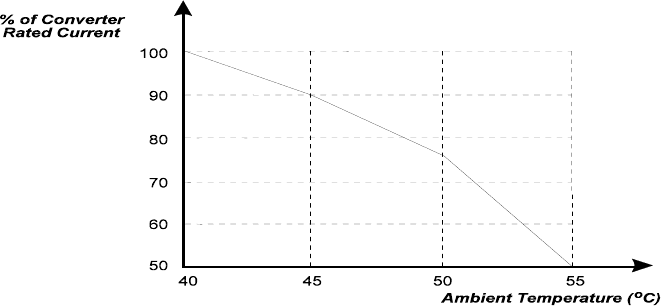
8.1.4 De-rating for high temperature
Figure 8.1:
Typical temperature de-rating chart for PWM converter
Installation and commissioning
In regions or environments where there is a high ambient temperature above the
accepted 40
o
C specified in the standards, both the motor and the converter need to be de-
rated, which means that they can only be run at loads that are less than their 40
o
C rating
to avoid thermal damage to the insulation materials.
The manufacturers of AC converters usually provide de-rating tables for high
temperature environments that are above 40
o
C. A typical table is given below for a
modern PWM converter. This table should be used as a guide only and should NOT be
taken to apply to AC converters in general or any converter in particular. The design of
AC converters is different from various manufacturers, so the cooling requirements are
never the same. The cooling requirements of different models from the same
manufacturer may also be different.
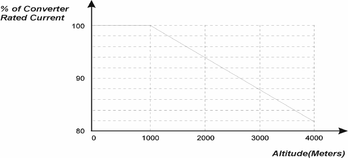
8.1.5 De-rating for high altitude
At high altitudes, the cooling of electrical equipment is degraded by the reduced ability of
the air to remove the heat from the motor or the heat-sink of the converter. The reason is
that the air pressure falls with increased altitude, air density falls and, consequently, its
thermal capacity is reduced.
In accordance with the standards, AC converters are rated for altitudes up to 1000
meters above sea level. Rated output should be de-rated for altitudes above that.
The manufacturers of AC converters usually provide de-rating tables for altitudes
higher than a 1000 m. A typical table is given below for a modern IGBT-type AC
converter. Note that this table is NOT applicable to all AC converters. The de-rating of
converters with high losses, such as those using BJTs or GTOs, will be much higher than
the de-rating required for low loss IGBT or MOSFET converters. The higher efficiency
of the latter requires less cooling and would therefore be less affected by altitude changes.
Figure 8.2:
Altitude de-rating chart for IGBT-type converter (Compliments of Allen-Bradley)
6U]KXY[VVR_IUTTKIZOUTYGTJKGXZNOTMXKW[OXKSKTZY
In accordance with accepted practice and the local, power is normally provided to a VSD
from a distribution board (DB) or a motor control center (MCC). Adequate arrangements
should be made to provide safety isolation switches and short-circuit protection in the
connection point to the power supply. The short-circuit protection is required to protect
Practical Variable Speed Drives and Power Electronics
the power cable to the AC converter and the input rectifier bridge at the converter. The
converter provides down-stream protection for the motor cable and the motor itself.
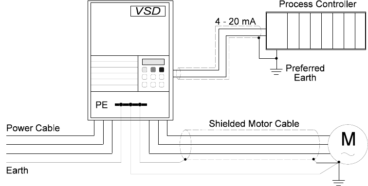
Adequate safety earthing should also be provided in accordance with the local wiring
rules and codes of practice. The metal frames of the AC Converter and the AC motor
should be earthed as shown in Figure 8.3 to keep touch potentials within safe limits. The
chassis of the AC converter is equipped with one or more protective earth (PE) terminals,
which should be connected back to common safety earth bar.
Figure 8.3:
Power supply, motor and earthing connections
8.2.1 Power supply cables
The variable speed drive should be connected to the power supply by means of a cable
that is adequate for the current rating of the VSD. Reference can be made to Australian
standard AS 3008 when selecting cables. The AC converter requires a 3-phase supply
cable (red/white/blue) and a protective earth conductor (green/yellow), which means a 4-
core cable with copper or aluminum conductors. A neutral conductor is not necessary and
is usually not brought to the frequency converter.
The AC converter is a source of harmonic currents that flow back into the low
impedance of the power supply system. This conducted harmonic current is carried into
other electrical equipment, where it causes additional heat losses and interference.
Sensitive electronic instrumentation, such as magnetic flow-meters, thermocouples and
other microprocessor based equipment, ideally should not be connected to the same
power source, unless via a filtered power supply.
Also, interference can be radiated from the power supply cable and coupled into other
circuits, so these cables should be routed well away from sensitive control circuits.
The power supply cable should preferably be laid in a metal duct or cable ladder and
shielded in some way to reduce the radiation of EM fields due to the harmonic currents.
Steel wire armored (SWA) cables, are particularly suitable for this purpose. If the power
cable is unshielded, control and communications cables should not be located within
about 300 mm of the power cable.
Installation and commissioning
The conductor sizes should be selected in accordance with normal economic cable
selection criteria, which take into account the maximum continuous current rating of the
VSD, the short-circuit rating, the length of the cable and the voltage of the power supply
system. The relevant local safety regulations should be strictly observed.
However, when selecting the cable cross-sectional area for the power supply cables and
upstream transformers, a de-rating factor of at least 10% should be included to
accommodate the additional heating due to the conducted harmonic currents (Chapter 4).
If a supply side harmonic filter is fitted at the converter, this may not be necessary. Three-
phase systems composed of three single-conductor cables should be avoided if possible.
Power cables with a trefoil configuration produce a lower radiated EM field.
8.2.2 Cables between converter and motor
The cable from the AC converter to the motor carries a switched PWM voltage, which is
modulated at high frequency by the inverter. This results in a higher level of harmonics
than the power supply cable. Harmonic frequencies are in the frequency spectrum of
100 kHz to 1 MHz. The motor cable should preferably be screened or located inside a
metal duct. Control and communications cables should not be located close to this cable.
The level of radiated EM fields is higher for cables with 3 separate single cores, laid
horizontally on a cable ladder, than a trefoil cable with a concentric shield.
The recommended size for the cable between the AC converter and the motor should
preferably be the same as the power supply cable. The reasons are:
• It will be easier to add a bypass device in parallel with the frequency
converter at a later date, using the same cable, cable lugs and connections.
• The load-carrying capacity of the motor cable is also reduced by harmonic
currents and additionally by the capacitive leakage currents.
It should be borne in mind that the AC converter VSD provides short-circuit and
overload protection for the cable and motor.
A separate earth conductor between the converter and motor is recommended for both
safety and noise attenuation. The earth conductor from the motor must be connected back
to the PE terminal of the converter and should not be connected back to the distribution
board. This will avoid any circulating high frequency currents in the earth system.
When armored or shielded cables are used between the converter and motor, it may be
necessary to fit a barrier termination gland at the motor end when the cable is longer than
about 50 m. The reason is that the high frequency leakage currents flow from the cable
through the shunt capacitance and into the shield. If these currents return via the motor
and other parts of the earthing system, the interference is spread over a larger area. It is
preferable for the leakage currents to return to the source via the shortest route, which is
via the shield itself. The shield or steel wire armor (SWA) should be earthed at both the
converter end and to the frame of the motor.
8.2.3 Control cables
The control cables should be provided in accordance with normal local practice. These
should have a cross-sectional area of at least 0.5 mm
2
for reasonable volt drop
performance. The control and communications cables connected to the converter should
be shielded to provide protection from EMI. The shields should be earthed at one end
only, at a point remote from the converter. Earthing the shield to the PE terminal of the
Practical Variable Speed Drives and Power Electronics
drive should be avoided because the converter is a large source of interference. The shield
should preferably be earthed at the equipment end.
Cables which have an individual screen for every pair provides the best protection from
coupled interference.
The control cables should preferably be installed on separate cable ladders or ducts, as
far away from the power cables as possible. If control cables are installed on the same
cable ladder as the power cables, the separation should be as far as possible, with the
minimum distance being about 300 mm. Long parallel runs on the same cable ladder
should be avoided.
8.2.4 Earthing requirements
As mentioned earlier, both the AC converter and the motor must be provided with a
safety earth according to the requirements of local standards. The main purpose of this
earthing is to avoid dangerous voltages on exposed metal parts under fault conditions.
When designing and installing these earth connections, the requirements for the
reduction of EMI should also be achieved with these same earth connections. The main
earthing connections of an AC converter are usually arranged as shown in Figure 8.3.
The PE terminal on the converter should be connected back to the system earth bar,
usually located in the distribution board. This connection should provide a low impedance
path back to earth.
8.2.5 Common cabling errors
The following are some of the common cabling errors made when installing VSDs:
• The earth conductor from the AC converter is run in the same duct or cable
ladder as other cables, such as control cables and power cables for other
equipment. Harmonic currents can be coupled into sensitive circuits. Ideally,
instrument cables should be run in separate metal ducts or steel conduit.
• Running unshielded motor cable next to the supply cable to the AC converter
or the power cables for other equipment. High frequency harmonic currents
can be coupled into the power cable, which can then be conducted to other
sensitive electronic equipment. Other cables should be separated from the
motor cable or converter power cable by a minimum of 300 mm.
• Running excessively long cables between the AC converter and the motor,
these should be no longer than 100 m. If longer cables are necessary, motor
filters are necessary to reduce the leakage current. Alternatively, the switching
frequency may be reduced.
9ZGXZYZUVIUTZXURUL')JXO\KY
The protection requirements for AC variable speed drives is covered in considerable
detail in Chapter 5: Protection of AC converters and motors. The protection of the mains
supply side of the converter requires short circuit protection either in the form of a set of
adequately rated fuses, usually as part of a switch-fuse unit, or a main circuit breaker.
The stop/start control of the AC drive can be achieved in a number of ways, mainly:
• Controlling the start/stop input of the converter control circuit
• Breaking the power circuit by means of a contactor
Installation and commissioning
The first method is the recommended method of controlling the stopping and starting of
an AC converter. This may be achieved by stop and start pushbuttons wired directly to
the control terminals of the converter as shown in Figure 8.7.
Alternatively, if the control is from a remote device such as a PLC, the control can be
wired from the PLC directly to the terminals of the AC converter as shown in Figure 8.8.
The second method is the one most commonly used for the direct on line (DOL)
starting of normal fixed speed AC motors. Following from previous DOL ‘standard’
practice, this method is also quite commonly used in industry for the control of variable
speed drives, particularly for conveyors. It is usually a safety requirement to interrupt the
power circuit when an emergency stop or pull-wire switch has been operated. While this
method satisfies the safety requirements by breaking the power supply to the motor, there
are a number of potential hazards with this method of control. The main problems are:
• Contactor on supply side of the AC converter
Opening/closing the supply side of the AC converter for stop/start control
should be avoided because most modern converters take their power from the
DC bus. Every time the power is removed
− Power to the control circuits is lost
− Control display goes off
− Diagnostic information disappears
− DC capacitors become discharged
− Serial communications are lost
When the AC variable speed drive needs to be restarted, there is a time delay
(typically 2 secs) while the DC bus charging system completes its sequence to
recharge the DC capacitor. This stresses the charging resistors, the DC
capacitor and other components. The charging resistors of many AC
converters are short-time rated and, although sometimes not highlighted in the
user manual, there is a limit to the number of starts that can be done. Many
users have the concept of ‘run on power up’ is acceptable and unrestricted.
The following is an extract from the manual of one of the leading
manufacturers of AC converters:
ATTENTION: The drive is intended to be controlled by control input signals
that will start and stop the motor. A device that routinely disconnects and then
reapplies line power to the drive for the purpose of starting and stopping the
motor is not recommended. If this type of circuit is used, a maximum of 3
stop/start cycles in any 5 minute period (with a minimum period of 1 minute
rest between each cycle) is required. These 5 minute periods must be
separated by 10 minute rest cycles to allow the drive precharge resistors to
cool. Refer to codes and standards applicable to your particular system for
specific requirements and additional information.
• Contactor on motor side of the AC converter
Opening/closing the 3-phase power circuit on the motor side of the AC
converter for stop/start control should also be avoided, particularly while the
AC drive is running. Breaking the inductive circuit to the motor produces
Practical Variable Speed Drives and Power Electronics
transient over-voltages which can damage the IGBTs and other components.
Many modern AC converters have RC suppression circuits (snubbers) to
protect the IGBTs from this type of switching. The following is an extract
from the manual of one of the leading manufacturers of AC converters:
ATTENTION: Any disconnecting means wired to the drive output terminals
U, V and W must be capable of disabling the drive if operated during drive
operation. If opened during drive operation, the drive will continue to produce
output voltage between U, V and W. An auxiliary contact must be used to
simultaneously disable the drive or output component damage may occur.
The objective is to ensure that the AC converter is OFF before the contacts
between the converter and the motor are opened. This will avoid IGBT
damage due to transient over-voltages.
In addition, closing the motor side contactor when converter output voltage is
present can result in a motor inrush current similar to DOL starting. Apart
from the stress this places on the converter, the drive will trip on over-current.
Repeated attempts at closing the motor contactor after the converter has
started may eventually lead to IGBT failure.
If a contactor has to be installed into the power circuit of an AC variable speed drive
system to meet local safety requirements, then it is better to locate this contactor
downstream of the AC converter. It is then necessary to include an auxiliary contact on
the contactor which disables the converter control circuit before the contactor is opened
or, alternatively, closes the enable circuit after the contactor has been closed. This means
that a late make - early break auxiliary contact should be used on the contactor and wired
to the converter enable input.
While the above configuration will protect the AC converter from failure, this method
of routine stop/start control is not recommended. It should be used for emergency stop
conditions only. Routine stop/start sequences should be done from the AC converter
control terminals. An alternative method of ensuring that plant operators follow this
requirement is to install a latching relay and a reset pushbutton. The latching relay needs
to be reset after every Emergency Stop sequence.
/TYZGRROTM')IUT\KXZKXYOTZUSKZGRKTIRUY[XKY
If the environmental conditions are likely to exceed these accepted working ranges, then
arrangements should be made to provide additional cooling and/or environmental
protection for the AC converter. The temperature limits of an AC converter are far more
critical than those for an electric motor. Temperature de-rating needs to be strictly
applied. However, it is unlikely that a modern PWM converter will be destroyed if the
temperature limits are exceeded. Modern AC converters have built-in thermal protection,
usually a silicon junction devices, mounted on the heat-sink. The main problem of over-
temperature tripping is associated with nuisance tripping and the associated downtime.
Although the efficiency of a modern AC converters is high, typically ± 97%, they all
generate a small amount of heat, mainly due to the commutation losses in the power
electronic circuits. The level of losses depends on the design of the converter, the PWM
switching frequency and the overall power rating. Manufacturers provide figures for the
losses (watts) when the converter is running at full load. Adequate provision should be
made to dissipate this heat into the external environment and to avoid the temperature
inside the converter enclosure rising to unacceptably high levels.
Installation and commissioning
Converters are usually air-cooled, either by convection (small power ratings) or assisted
by cooling fans on larger power ratings. Any obstruction to the cooling air flow volume
to the intake and from the exhaust vents will reduce efficiency of the cooling. The cooling
air volume flows and the power loss dissipation determine the air-conditioning
requirements for the equipment room.
The cooling is also dependent on there being a temperature differential between the
heat-sink and the cooling air. The higher the ambient temperature, the less effective is the
cooling. Both the AC converter and motor are rated for operation in an environment
where temperature does not exceed 40
o
C.
When AC converters are mounted inside enclosures, care should be taken to ensure that
the air temperature inside the enclosure remains within the specified temperature limits. If
not, the converters should be de-rated in accordance with the manufacturer’s de-rating
tables.
In an environment where condensation is likely to occur during the periods when the
drive is not in use, anti-condensation heaters can be installed inside the enclosure. The
control circuit should be designed to switch the heater on when the drive is de-energised.
The heater maintains a warm dry environment inside the enclosure and avoids moisture
being drawn into the enclosure when the converter is switched off and cools down.
AC converters are usually designed for mounting in a vertical position, to assist
convectional cooling. On larger VSDs, cooling is assisted by one or more fans mounted at
the bottom or top of the heat-sink.
Many modern converters allow two alternative mounting arrangements:
• Surface mounting, where the back plane of the converter is mounted onto a
vertical surface, such as the back of an enclosure. (Figure 8.4 and 8.5)
• Recessed mounting, where the heat-sinks on the back of the converter project
through the back of the enclosure into a cooling duct. This allows the heat to
be more effectively dissipated from the heat-sinks. (Figure 8.6)
Sufficient separation from other equipment is necessary to permit the unrestricted flow
of cooling air through the heat-sinks and across the electronic control cards. A general
rule of thumb is that a free space of 100 mm should be allowed around all sides of the
VSD. When more than one VSD are located in the same enclosure, they should
preferably be mounted side by side rather than one above the other. Care should also be
taken to avoid locating temperature sensitive equipment, such as thermal overloads,
immediately above the cooling air path of the VSD.
Adequate provision must be made to dissipate the converter losses into the external
environment. The temperature rise inside the enclosure must be kept below the maximum
rated temperature of the converter.
8.4.1 Calculating the dimensions of the enclosure
The enclosure should be large enough to dissipate the heat generated by the converter and
any other electrical equipment mounted inside the enclosure. The heat generated inside an
enclosure is transferred to the external environment mainly by radiation from the surface
of the enclosure. Consequently, the surface area must be large enough to dissipate the
internally generated heat without allowing the internal temperature to exceed rated limits.

Practical Variable Speed Drives and Power Electronics
The surface area of a suitable enclosure is calculated as follows:
)
T
T
k(
P
= A
AmbMax
−
where: A Effective heat conducting area in m
2
(Sum of surface areas not in contact with any other surface)
P Power loss of heat producing equipment in watts
T
Max
Maximum permissible operating temperature of converter in
o
C
T
Amb
Maximum temperature of the external ambient air in
o
C
k Heat transmission coefficient of enclosure material
Example:
Calculate the minimum size of an IP54 cubicle for a typical PWM type frequency
converter rated at 22 kW. The following assumptions are made:
• The converter losses are 600 watts at full rated load.
• The converter is to be mounted within an IP54 cubicle made of 2 mm steel.
• The enclosure is effectively sealed from the outside and heat can only be
dissipated from the enclosure by conduction through the steel and by radiation
from the external surface into the outside air.
• The cubicle stands on the floor with its back against the wall in an air-
conditioned room with a maximum ambient temperature 25
o
C.
• The converter can operate in a maximum temperature of 50
o
C.
• The heat transmission coefficient is 5.5 (typical for painted 2 mm steel).
The first step is to calculate the minimum required surface area of the enclosure. This
can be done by applying the formula for surface area.
m
4.36 =
25) 5.5(50
600
2
−
= A
If the cubicle is standing on the floor against a wall, this area applies only to the top,
front and two sides of the enclosure. A suitable cubicle can be chosen from a range of
standard cubicles or could be fabricated for this installation. In either case, it is important
to take into account the dimensions of the converter and to ensure that there is at least
100 mm space on all sides of the converter.
With these requirements in mind, the procedure is to choose or estimate at least two of
the dimensions and the third can be derived from the above equation. This calculated
dimension must then be checked to ensure that the required 100 mm clearance is
maintained.
For a cubicle with dimensions H × W × D standing on the floor against the wall, the
effective heat conducting area is
A = HW + 2HD + WD