Malcolm Barnes. Practical Variable Speed Drives and Power Electronics
Подождите немного. Документ загружается.


Motor protection – direct temperature sensing 239
•
IEC 584 – International Electrotechnical Commission (IEC)
This is a new standard that will start to gain acceptance in the future.
Hopefully, it will overcome much of the confusion that currently exists with
thermocouple color-codes.
Type Temp range Metals
+ve –ve
NBS colors BS colors
J-Type
0ºC to 750ºC Iron Constantan White/Red
Brown Sheath
Yellow/Blue
Black Sheath
K-Type
–200ºC to 1250ºC Copper Nickel Yellow/Red
Brown Sheath
Brown/Blue
Red Sheath
N-Type
–270ºC to 1300ºC Nicrosil Nisil Orange/Red
Brown Sheath
Orange/Blue
Orange Sheath
E-Type
–200ºC to 900ºC Chromel Constantan Purple/Red
Brown Sheath
Brown/Blue
Brown Sheath
T-Type
–200ºC to 350ºC Copper Constantan Blue/Red
Brown Sheath
White/Blue
Blue Sheath
Figure A.6:
Details of the most common base-metal thermocouples, with the ANSI-NBS and BS 1843 color-codes
As temperature sensors, thermocouples have the following main advantages:
• Robust: very suitable for the industrial environment
• Good accuracy: typically 0.5% per 1
o
C
• Low cost: consist of a junction of two dissimilar metals
• Self powered: thermal energy is converted into electrical energy
• Wide temp range: types are available for most temperature ranges
The materials used for thermocouple junctions are either base metals or noble metals.
base-metal thermocouples are most commonly used in industry because of their lower
cost. Thermocouples made from noble metals are more expensive and are used for special
applications, where corrosion may be a problem. There are also a number of very high
temperature thermocouples, usually made from tungsten.
Conventional copper wire should not be used to connect thermocouples to the
temperature controller. This would introduce additional junctions into the circuit and lead
to substantial temperature sensing errors. Special thermocouple wire, using the same
materials as the thermocouple junction, should be used to connect the junction to the
controller. Thermocouple extension wires are usually also color-coded to match the
thermocouple colors.
Thermocouple connections are also susceptible to external electrical interference and
induced voltages, superimposed onto the junction voltage, will result in measurement
errors. Extension wires should not be run along cable routes together with high voltage or
high current power cables. Screened extension wires should be used in cases where there
is a high level of noise. On industrial sites, it is common practice to run thermocouple
extension cables inside galvanized iron conduits, which provide physical protection and
shielding against electrical noise.

240 Practical Variable Speed Drives and Power Electronics
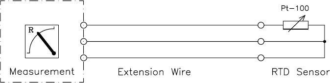
A.5 Resistance temperature detector (RTD)
Name of Sensor Metal Resistance at 0ºC
Cu-10
Pt-100
Ni-120
Copper
Platinum
Nickel
10 Ω
100 Ω
120 Ω
Figure A.7:
The most common types of RTD sensors
Resistance temperature detectors (RTDs) monitor temperature by measuring the change
of resistance of an accurately calibrated resistive sensor, usually made of copper,
platinum or nickel. Tungsten is sometimes used for high temperature applications. RTD
sensors can be of the wire wound type, which have a high stability over a period of time,
or can be of the metal film types, which are lower cost with faster response but their
characteristics can deteriorate over a period of time.
The type of RTD sensor most commonly used in electrical machines comprises a
Pt-100 sensor
element made of platinum, whose resistance is accurately calibrated to
100 Ω at 0
o
C. The sensor is usually insulated and mounted inside a cylindrical metal tube
of dimensions typically 10 mm diameter and 200 mm length.
Since the RTD sensor is physically larger than other types of measuring sensors, it
cannot easily be mounted in the windings or bearings of small electric motors.
Consequently, RTDs are only used on large machines, where they are installed within the
stator slots during manufacture. A slightly different mechanical form is used for mounting
in bearing housings. Thermistors or thermocouples are still the most commonly used
temperature sensors for electric motors.
An RTD has a linear relationship between resistance and temperature, typically
0.4 Ω/
o
C for a Pt-100 sensor. A very sensitive measuring instrument, usually based on the
Wheatstone bridge, is required to continuously measure the small changes in the
resistance of the RTD. These instruments pass a small excitation current through the
resistive sensor.
Although the excitation current can cause some problems with self-heating, this is
seldom a problem because the currents are small, typically less than 1 mA, and RTDs
have a high rate of heat dissipation along the connecting wires and to the measured
medium.
Considering the small changes of resistance with temperature, the overall accuracy of
the RTD resistance measurement is affected by the series loop resistance of the extension
wire between the measuring instrument and the Pt-100 sensor. This is dependent on the
cross-sectional area of the wires and the distance between the RTD sensor and the
measuring instrument. This has led to the development of 3-wire RTDs, where a third
identical extension wire is connected between the instrument and the sensor. The purpose
of the third wire is to provide the measuring instrument with a means of measuring the
wire loop resistance to the RTD sensor. To improve accuracy, this is subtracted from the
total measured resistance. At the RTD sensor, the third wire is simply connected to one of
the legs of the sensor as shown in Figure A.8.
Motor protection – direct temperature sensing 241
Figure A.8:
Connections for a 3-wire resistance temperature detector
In a similar way to thermistors and thermocouples, the RTD connections are also
susceptible to external electrical interference and induced voltages, which can lead to
measurement errors. Similar precautions need to be taken with the cable route selection
and screening. RTDs have become very popular in industry because they provide low
cost, high accuracy temperature measurement with a relatively fast thermal response.

242 Practical Variable Speed Drives and Power Electronics
Pt-100: Resistances for temperatures 0
o
C to +299
o
C : DIN 43760
ºC + 0ºC + 1ºC + 2ºC + 3ºC + 4ºC + 5ºC + 6ºC + 7ºC + 8ºC + 9ºC
0
+10
+20
+30
+40
+50
+60
+70
+80
+90
+100
+110
+120
+130
+140
+150
+160
+170
+180
+190
+200
+210
+220
+230
+240
+250
+260
+270
+280
+290
100.00
103.90
107.79
111.67
115.54
119.40
123.24
127.07
130.89
134.70
138.50
142.29
146.06
149.83
153.58
157.32
161.05
164.76
168.47
172.16
175.84
179.51
183.17
186.82
190.45
194.08
197.69
201.29
204.88
208.46
100.39
104.29
108.18
112.06
115.93
119.78
123.62
127.46
131.28
135.08
138.88
142.67
146.44
150.20
153.95
157.69
161.42
165.13
168.84
172.53
176.21
179.88
183.54
187.18
190.82
194.44
198.05
201.65
205.24
208.82
100.78
104.68
108.57
112.45
116.31
120.17
124.01
127.84
131.66
135.46
139.26
143.04
146.82
150.58
154.33
158.06
161.79
165.50
169.21
172.90
176.58
180.25
183.90
187.55
191.18
194.80
198.41
202.01
205.60
209.17
101.17
105.07
108.96
112.83
116.70
120.50
124.39
128.22
132.04
135.84
139.64
143.42
147.19
150.95
154.70
158.44
162.16
165.88
169.58
173.27
176.95
180.61
184.27
187.91
191.54
195.16
198.77
202.37
205.96
209.53
101.56
105.46
109.35
113.22
117.08
120.94
124.77
128.60
132.42
136.22
140.02
143.80
147.57
151.33
155.07
158.81
162.53
166.25
169.95
173.64
177.31
180.98
184.63
188.27
191.91
195.53
199.13
202.73
206.31
209.89
101.95
105.85
109.73
113.61
117.47
121.32
125.16
128.99
132.80
136.60
140.40
144.18
147.95
151.70
155.45
159.18
162.91
166.62
170.32
174.00
177.68
181.34
185.00
188.64
192.27
195.89
199.49
203.09
206.67
210.24
102.34
106.24
110.12
113.99
117.85
121.70
125.54
129.37
133.18
136.98
140.78
144.55
148.32
152.08
155.82
159.56
163.28
166.99
170.69
174.37
178.05
181.71
185.36
189.00
192.63
196.25
199.85
203.45
207.03
210.60
102.73
106.63
110.51
114.38
118.24
122.09
125.92
129.75
133.56
137.36
141.15
144.93
148.70
152.45
156.20
159.93
163.65
167.36
171.05
174.74
178.41
182.08
185.73
189.37
192.99
196.61
200.21
203.81
207.39
210.96
103.12
107.02
110.90
114.77
118.63
122.47
126.31
130.13
133.94
137.74
141.53
145.31
149.07
152.83
156.57
160.30
164.02
167.73
171.42
175.11
178.78
182.44
186.09
189.73
193.35
196.97
200.57
204.16
207.74
211.31
103.51
107.40
111.28
115.15
119.01
122.86
126.69
130.51
134.32
138.12
141.91
145.69
149.45
153.20
156.94
160.67
164.39
168.10
171.79
175.48
179.15
182.81
186.46
190.09
193.72
197.33
200.93
204.52
208.10
211.67
Figure A.9:
Pt-100 sensor – variation of resistance with temperature over range 0
o
C to +299
o
C

Motor protection – direct temperature sensing 243
Pt-100: Resistances for temperatures 0
o
C to –219
o
C : DIN 43760
ºC –0ºC –1ºC –2ºC –3ºC –4ºC –5ºC –6ºC –7ºC –8ºC –9ºC
0
–10
–20
–30
–40
–50
–60
–70
–80
–90
–100
–110
–120
–130
–140
–150
–160
–170
–180
–190
–200
–210
100.00
96.07
92.13
88.17
84.21
80.25
76.28
72.29
68.28
64.25
60.20
56.13
52.04
47.93
43.80
39.65
35.48
31.28
27.05
22.78
18.53
14.36
99.61
95.68
91.73
87.77
83.81
79.85
75.88
71.89
67.88
63.84
59.79
55.72
51.63
47.52
43.38
39.23
35.06
30.86
26.62
22.35
18.11
13.96
99.21
95.28
91.34
87.38
83.42
79.46
75.48
71.49
67.47
63.44
59.39
55.31
51.22
47.10
42.97
38.82
34.64
30.43
26.20
21.93
17.70
13.57
98.82
94.89
90.94
86.98
83.02
79.06
75.08
71.09
67.07
63.03
58.98
54.90
50.81
46.69
42.55
38.40
34.22
30.01
25.77
21.50
17.28
13.17
98.43
94.49
90.55
86.59
82.63
78.66
74.68
70.69
66.67
62.63
58.57
54.49
50.40
46.28
42.14
37.98
33.80
29.59
25.34
21.08
16.86
12.78
98.03
94.10
90.15
86.19
82.23
78.26
74.28
70.28
66.26
62.22
58.16
54.08
49.98
45.86
41.72
37.56
33.38
29.16
24.91
20.65
16.44
12.38
97.64
93.71
89.75
85.79
81.83
77.87
73.89
69.88
65.86
61.82
57.76
53.68
49.57
45.45
41.31
37.15
32.96
28.74
24.49
20.23
16.03
11.99
97.25
93.31
89.36
85.40
81.44
77.47
73.49
69.48
65.46
61.41
57.35
53.27
49.16
45.04
40.89
36.73
32.54
28.32
24.06
19.80
15.61
11.59
96.86
92.92
88.96
85.00
81.04
77.07
73.09
69.08
65.06
61.01
56.94
52.86
48.75
44.63
40.48
36.31
32.12
27.90
23.63
19.38
15.19
11.20
96.46
92.52
88.57
84.61
80.65
76.68
72.69
68.68
64.65
60.60
56.54
52.45
48.34
44.21
40.06
35.90
31.70
27.47
23.21
18.95
14.78
10.80
Figure A.10:
Pt-100 sensor – variation of resistance with temperature over range 0
o
C to –219
o
C
Appendix B
Current measurement transducers
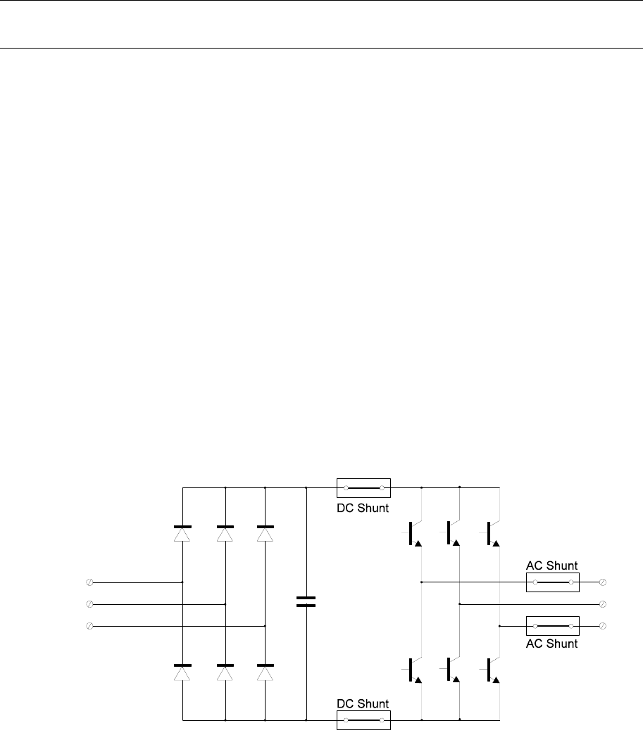
B.1 Current shunt
A current shunt and amplifier is the simplest form of current feedback. This well
established technique is illustrated in Figure B.1 the DC bus current is passed through a
link of pre-calibrated resistance and the voltage across it is measured. The voltage is
directly proportional to the current passing through the shunt.
Figure B.1:
Shunt voltages to earth on an AC converter
The main problem with this device is one of electrical
isolation. To measure the DC bus
current in a PWM AC converter, the shunt must be located in the positive or negative leg
of the DC bus, and will therefore be at some voltage above (or below) earth potential as
Current measurement transducers
245
shown in the Figure B.1. This problem of isolation also occurs when measuring currents
in the output phases to the motor.
The simplest way to overcome this problem is to reference the control circuit to the
shunt potential, which may be around 300 V above earth. While this approach was
adopted in many early AC VSDs, it is no longer considered acceptable as it poses
interface and safety problems when control devices are connected to the drive.
Another approach is to galvanically isolate the shunt circuit from the rest of the control
circuit with an isolation amplifier. This can be achieved with discrete circuitry
incorporating either opto-couplers or signal transformers. However, it adds significantly
to the complexity and cost of the current feedback circuitry.
Current shunts are seldom used in digital VSDs. Hall effect sensors are far more
common.
B.2
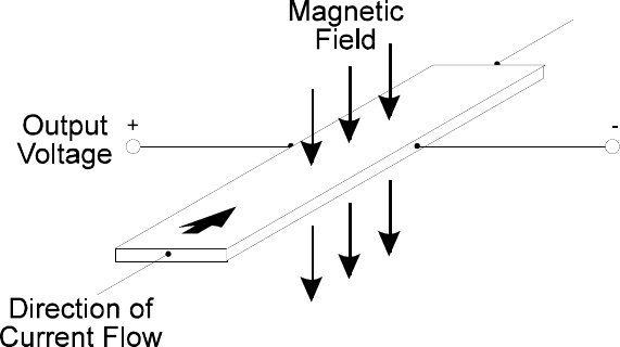
Principle of the Hall effect sensor
The fundamental principle of the Hall effect sensor is shown in Figure B.2. The current
flowing through a semi-conductor material establishes a magnetic field in a plane
perpendicular to the current, which forces the moving carriers to crowd to one side of the
conductor. As a result of this crowding, a Hall voltage will develop perpendicular to both
the current and the magnetic field.
Figure B.2:
Principle of the Hall effect current sensor
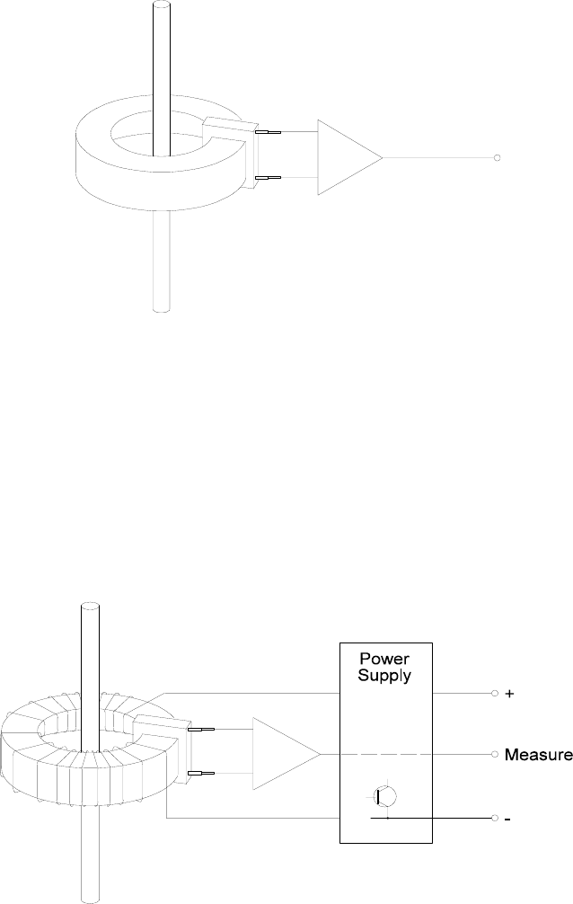
B.2.1 Open-loop Hall effect sensor
If a Hall effect semi-conductor integrated circuit is placed in the air-gap of a toroidal
magnetic core enclosing a current carrying conductor, the output voltage of the Hall
device is proportional to the current in the main conductor. This configuration is shown in
the Figure B.3 below. Thus a current measurement signal is produced which is inherently
isolated from the primary current being measured and with a small number of
components. This device also has a relatively high bandwidth of around 10 kHz.
While this method is simple and cheap to manufacture, the performance of this Hall
device is variable and each combination of core and device must be carefully trimmed.
This is usually done at the desired current trip point for the drive so as to achieve
maximum accuracy during fault conditions. Measurement errors will then be present at
246
Practical Variable Speed Drives and Power Electronics
normal operating currents and will be greatest at zero current. In practice, this is not
usually a major problem in general purpose AC drives, as the current signal is mainly
used for current limit control and power device protection.
However, because of these inherent problems, the open-loop Hall effect sensor is not
commonly used on larger VSDs, but is quite common for small VSDs.
Figure B.3:
Principle of the open-loop Hall effect current sensor
B.2.2 Closed-loop Hall effect sensor
A method of overcoming the accuracy and repeatability problems of the open-loop sensor
is to include a feedback loop to null the flux in the magnetic core. This is the basic
principle of the well-known LEM (manufacturer’s name) Hall effect current sensing
modules, which are widely used in most modern VSDs. The configuration of this device
is shown in Figure B.4 below.
Figure B.4:
Principle of the LEM Hall effect current sensor

Current measurement transducers
247
In the closed-loop module, the secondary winding has many more turns than the
primary winding, which carries the primary current being measured. An amplifier is used
to drive current into this secondary winding so that the net magnetic field in the core is
zero. At this point, the secondary current, I
S
is given by:
TurnsSecondary of No.
TurnsPrimary of No.
I
=
I
PS
×
The main advantage of the closed-loop method is high accuracy and repeatability over a
large signal range. Bandwidth is still good (around 10 kHz), although the performance of
the amplifier is critical in achieving high bandwidth. These models also have significant
power supply requirements, as the secondary winding current will be related to the
maximum primary current times the turns ratio as shown in the equation above. For
example, a LEM module with a 1000:1 turns ratio, will draw 100 mA if the primary
current to be measured is 100 A.
In addition to the high current requirement, the LEM usually requires a DC power
supply of about 15 V DC in order to achieve a high rate of change of current in the
secondary winding. This high di/dt is also necessary to maintain high bandwidth.
While closed-loop devices are generally considered superior due to their excellent
accuracy, repeatability and good bandwidth, they tend to be used mainly in larger drives.
Smaller VSDs (below 4 kW) cannot justify their high cost and power supply
requirements, so the open-loop Hall sensor is commonly used at this power level.

Appendix C
Speed measurement transducers
C.1 Analog speed transducers
A tachometer generator or tacho-generator (abbreviation: tacho) is a small
electromagnetic generator that is usually fitted to the non-drive end (NDE) shaft of an
electric motor. Tacho-generators can be either of the flange-mounted, solid-shaft type or
the hollow-shaft type.
Since tachos are usually small in size relative to the motors to which they are attached,
the flange-mounted type is susceptible to damage due to excessive axial forces.
Consequently, special care needs to be taken with the coupling between the tacho and
motor shaft to avoid problems with alignment and the difficult fitting and removal
operations associated with maintenance. Misalignment can also result in a low frequency
ripple that is difficult to filter out. The commonly used ‘bellows’ type of coupling is
designed to absorb axial forces and vibration, which reduce the life of the brushes, and
also allows for minor misalignment. External magnetic fields can also affect the output of
a tacho-generator.
Hollow-shaft tachos overcome many of the mounting difficulties of the flange-mounted
tachos. The following are the two most common methods of mounting hollow-shaft
tachos:
• Hollow-shaft tacho with separate rotor and stator parts
The rotor is mounted directly onto a stub-shaft at the NDE end of the rotating
machine, using either a keyway or a friction press-fit. The stub-shaft diameter
is typically in the range 8 mm to 16 mm. The stator is fixed onto a flange on
the bearing housing of the machine. No bearings are supplied with this type of
hollow-shaft tacho. However, care must be taken to ensure that the tacho rotor
is concentric with the tacho stator. The brush holders and cable connections
are mounted on the stator frame.
• Integral hollow-shaft tacho with bearings
These units are complete with bearings and suitable for direct mounting onto a
stub-shaft at the NDE end of the rotating machine. To prevent the stator from