Marsh D. Applied Geometry for Computer Graphics and CAD
Подождите немного. Документ загружается.


4. Projections and the Viewing Pipeline 77
a3× 4 matrix K such that P
K = P
, and then to express VC is terms of K.
The reason for this is that K has a simple derivation.
The matrix K can be determined if the homogeneous world coordinates,
and corresponding viewplane coordinates, of four points on the viewplane are
known. Consider the following four points (expressed in homogeneous world
coordinates):
(1) the origin O(q
1
,q
2
,q
3
, 1),
(2) the point at infinity R(r
1
,r
2
,r
3
, 0) in the direction of the X-axis,
(3) the point at infinity S(s
1
,s
2
,s
3
, 0) in the direction of the Y -axis, and
(4) the point T(t
1
,t
2
,t
3
, 1) = (q
1
+ r
1
+ s
1
,q
2
+ r
2
+ s
2
,q
3
+ r
3
+ s
3
, 1) which is
one unit in the X-direction and one unit in the Y -direction from the origin.
The homogeneous viewplane coordinates of the four points are (0, 0, 1), (1, 0, 0),
(0, 1, 0), and (1, 1, 1) respectively. Then
⎛
⎜
⎜
⎝
O
R
S
T
⎞
⎟
⎟
⎠
=
⎛
⎜
⎜
⎝
q
1
q
2
q
3
1
r
1
r
2
r
3
0
s
1
s
2
s
3
0
t
1
t
2
t
3
1
⎞
⎟
⎟
⎠
=
⎛
⎜
⎜
⎝
001
100
010
111
⎞
⎟
⎟
⎠
⎛
⎝
r
1
r
2
r
3
0
s
1
s
2
s
3
0
q
1
q
2
q
3
1
⎞
⎠
,
and so corresponding points are correctly mapped to each other. Hence the
required matrix is
K =
⎛
⎝
r
1
r
2
r
3
0
s
1
s
2
s
3
0
q
1
q
2
q
3
1
⎞
⎠
. (4.1)
The viewplane coordinate mapping is an inverse of the mapping determined
by the matrix K.SinceK is not a square matrix there is no matrix inverse K
−1
,
but there is a right inverse,a4× 3 matrix denoted K
R
, for which KK
R
= I
3
.
Since KK
T
(KK
T
)
−1
= I
3
, a right inverse of K is K
R
= K
T
(KK
T
)
−1
.Further,
since P
= P
K it follows that
P
K
R
= P
K
T
(KK
T
)
−1
=(P
K) K
T
(KK
T
)
−1
= P
KK
T
(KK
T
)
−1
= P
.
Hence the viewplane coordinate mapping P
= P
VC is given by the matrix
VC = K
R
= K
T
(KK
T
)
−1
.
Observe that the viewplane coordinate matrix VC does not depend on a
particular projection but is determined by the choice of origin and the directions
of the X-andY -axes. Thus VC can be applied to any view of an object.

78 Applied Geometry for Computer Graphics and CAD
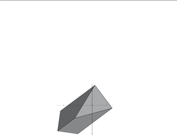
Example 4.8
Consider the perspective projection of the prism onto the plane z =0from
the viewpoint V(1, 5, 3) determined in Example 4.7. Let a coordinate system
on the viewplane be given by origin O(1, 2, 0), X-axis direction (3, 4, 0), and
Y -axis direction (−4, 3, 0). Then the unit vectors in the directions of the axes
are r =(3/5, 4/5, 0) and s =(−4/5, 3/5, 0). The viewplane coordinate matrix
VC = K
T
(KK
T
)
−1
is obtained in several steps:
KK
T
=
⎛
⎝
3/54/500
−4/53/500
1201
⎞
⎠
⎛
⎜
⎜
⎝
3/5 −4/51
4/53/52
000
001
⎞
⎟
⎟
⎠
=
⎛
⎝
1011/5
012/5
11/52/56
⎞
⎠
,
(KK
T
)
−1
=
⎛
⎝
146/25 22/25 −11/5
22/25 29/25 −2/5
−11/5 −2/51
⎞
⎠
,
VC =
⎛
⎜
⎜
⎝
3/5 −4/51
4/53/52
000
001
⎞
⎟
⎟
⎠
⎛
⎝
146/25 22/25 −11/5
22/25 29/25 −2/5
−11/5 −2/51
⎞
⎠
=
⎛
⎜
⎜
⎝
3/5 −4/50
4/53/50
000
−11/5 −2/51
⎞
⎟
⎟
⎠
.
The homogeneous viewplane coordinates of the prism vertices are determined
by applying VC to the projected vertices obtained in Example 4.7:
⎛
⎜
⎜
⎜
⎜
⎜
⎜
⎜
⎝
A
B
C
D
E
F
⎞
⎟
⎟
⎟
⎟
⎟
⎟
⎟
⎠
=
⎛
⎜
⎜
⎜
⎜
⎜
⎜
⎜
⎝
000−3
−600−3
−6 −90−3
0 −90−3
−2 −10−2
−220−2
⎞
⎟
⎟
⎟
⎟
⎟
⎟
⎟
⎠
⎛
⎜
⎜
⎝
3/5 −4/50
4/53/50
000
−11/5 −2/51
⎞
⎟
⎟
⎠
4. Projections and the Viewing Pipeline 79
=
⎛
⎜
⎜
⎜
⎜
⎜
⎜
⎜
⎝
33/56/5 −3
36−3
−21/53/5 −3
−3/5 −21/5 −3
12/59/5 −2
24/518/5 −2
⎞
⎟
⎟
⎟
⎟
⎟
⎟
⎟
⎠
.
Hence, the Cartesian viewplane coordinates of the vertices are A
(−11/5, −2/5),
B
(−1, −2), C
(7/5, −1/5), D
(1/5, 7/5), E
(−6/5, −9/10), F
(−12/5, −9/5).
The projected prism in viewplane coordinates is illustrated in Figure 4.9.
-2
-1
0
1
Y
-2 -1 1
X
Figure 4.9 Projected prism of Example 4.8 in viewplane coordinates
EXERCISES
4.12. Consider the perspective projection of the prism onto the z =0
plane from the viewpoint V(1, 5, 3) determined in Example 4.7. Let a
coordinate system on the viewplane be given by origin O(4, 3, 0), X-
axis direction (12, 5, 0), and Y -axis direction (−5, 12, 0). Determine
the viewplane coordinate matrix VC.(Rememberr and s must be
unit vectors.) Apply VC to the vertices of the prism and make a
sketch of the image.
4.13. Consider the projection of the tetrahedron with vertices (0, 1, 0),
(3, 1, 1), (−1, −1, 1), (0, −2, −1) onto the viewplane 5x − 3z +2=0
from the viewpoint (1, 4, −1) determined in Exercises 4.7 and 4.10.
Let a viewplane coordinate system be defined by origin O(−1, 1, 1),
X-axis direction (3, 0, 5), and Y -axis direction (0, −1, 0). Determine
the viewplane coordinate matrix VC. Apply the matrix to the vertices
of the projected tetrahedron, and make a sketch of the image.
4.14. Implement the viewplane coordinate mapping using a computer
package, or by writing a computer program, with the following spec-
80 Applied Geometry for Computer Graphics and CAD
ification. The viewplane vector, origin and axes directions are given
as input. The following checks on the input are carried out: that the
origin is a point on the plane, that the axes directions are perpendic-
ular, and that the axes directions are perpendicular to the plane vec-
tor. The matrix VC is determined and applied to input data points,
or concatenated with a projection matrix. Most computer algebra
packages have a procedure for determining matrix inverses. A sub-
routine to obtain a 3 × 3 matrix inverse is available on the book
website (see the Preface to the Second Edition).
4.5 The Viewing Pipeline
So far two stages of the viewing pipeline have been considered in detail. First,
the projection onto a viewplane P
= PM derived in Section 4.3, and second,
the viewplane coordinate mapping P
= P
VC derived in Section 4.4. The
final stage to be considered is the device coordinate transformation P
=
P
DC which was introduced in Section 2.6.2. The concatenation of these three
transformations yields the viewing pipeline which has the form P
= PVP
where VP = M · VC · DC.
X
Y
Device coordinate
transformation
Device coordinate
transformation
(,)XY
min min
(,)XY
min min
(,)XY
max max
(,)XY
max max
U
V
(U ,V )
min min
(U ,V )
min min
(U ,V )
max max
(U ,V )
max max
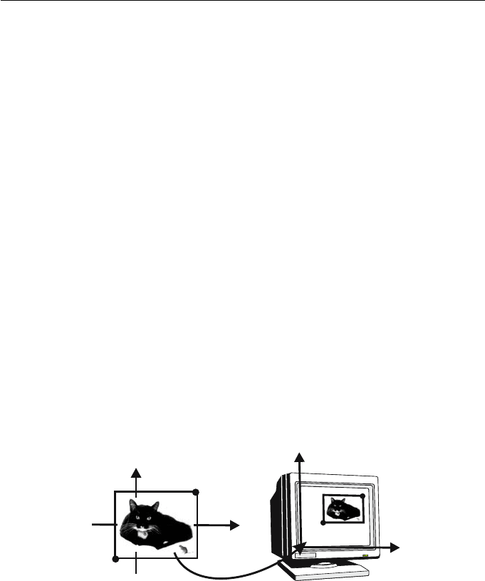
Figure 4.10
Referring to Figure 4.10, the region of the viewplane to be displayed is
specified by a rectangular viewplane window with lower left corner (X
min
,Y
min
)
and upper right corner (X
max
,Y
max
). This window is mapped to a rectangular
region in the device coordinate system (called the device or viewport window)
with lower left corner (U
min
,V
min
) and upper right corner (U
max
,V
max
). The
device coordinate transformation which maps the viewplane window with local

4. Projections and the Viewing Pipeline 81
coordinates (X, Y, Z) to homogeneous device coordinates (U, V, W ) is obtained
by a concatenation of planar transformations: a translation taking the lower
left corner of the viewplane window to the origin, followed by a scaling about
the origin (so that the translated viewplane window has the same size as the
device window), followed by a translation mapping the origin to the lower left
corner of the device window. The required device coordinate transformation is
DC = T(−X
min
, −Y
min
) · S
U
max
−U
min
X
max
−X
min
,
V
max
−V
min
Y
max
−Y
min
· T(U
min
,V
min
)
=
⎛
⎝
100
010
−X
min
−Y
min
1
⎞
⎠
⎛
⎜
⎝
U
max
−U
min
X
max
−X
min
00
0
V
max
−V
min
Y
max
−Y
min
0
001
⎞
⎟
⎠
×
⎛
⎝
100
010
U
min
V
min
1
⎞
⎠
.
Thus
DC =
⎛
⎜
⎜
⎜
⎜
⎜
⎝
U
max
−U
min
X
max
−X
min
00
0
V
max
−V
min
Y
max
−Y
min
0
X
max
U
min
−X
min
U
max
X
max
−X
min
Y
max
V
min
−Y
min
V
max
Y
max
−Y
min
1
⎞
⎟
⎟
⎟
⎟
⎟
⎠
.
The matrix DC is most easily remembered by recalling the transformations
which define it.
Example 4.9
Consider the projected prism of Example 4.8. Let a viewplane window be
given by lower left corner (X
min
,Y
min
)=(−3, −3) and upper right corner
(X
max
,Y
max
)=(3, 2). Suppose that the device is a computer screen with a res-
olution of 1280×1024 pixels, and that the origin of the device coordinate system
is the lower left corner of the screen. Let the device window have lower left cor-
ner (U
min
,V
min
) = (500, 400) and upper right corner (U
max
,V
max
) = (980, 700).
The device coordinate transformation matrix is
DC =
⎛
⎝
100
010
331
⎞
⎠
⎛
⎜
⎝
980−500
3−(−3)
00
0
700−400
2−(−3)
0
001
⎞
⎟
⎠
⎛
⎝
100
010
500 400 1
⎞
⎠
=
⎛
⎝
80 0 0
0600
740 580 1
⎞
⎠
.

82 Applied Geometry for Computer Graphics and CAD
To map the projected prism to the screen, the matrix DC is applied to the
homogeneous viewplane coordinates of the vertices given in Example 4.8:
⎛
⎜
⎜
⎜
⎜
⎜
⎜
⎜
⎝
A
B
C
D
E
F
⎞
⎟
⎟
⎟
⎟
⎟
⎟
⎟
⎠
DC =
⎛
⎜
⎜
⎜
⎜
⎜
⎜
⎜
⎝
33/56/5 −3
36−3
−21/53/5 −3
−3/5 −21/5 −3
12/59/5 −2
24/518/5 −2
⎞
⎟
⎟
⎟
⎟
⎟
⎟
⎟
⎠
⎛
⎝
80 0 0
0600
740 580 1
⎞
⎠
=
⎛
⎜
⎜
⎜
⎜
⎜
⎜
⎜
⎝
−1692 −1668 −3
−1980 −1380 −3
−2556 −1704 −3
−2268 −1992 −3
−1288 −1052 −2
−1096 −944 −2
⎞
⎟
⎟
⎟
⎟
⎟
⎟
⎟
⎠
.
The vertices in Cartesian device coordinates are (564, 556), (660, 460), (852, 568),
(756, 664), (644, 526), (548, 472). The reader is left the exercise of sketching the
screen and the device window containing the final image of the prism.
Remark 4.10
During the viewing pipeline, it is unnecessary to convert computed coordinates
from homogeneous to Cartesian until after all three matrices M, VC, DC have
been applied. It is generally most efficient to compute the viewing pipeline
matrix VP and then to apply VP to the coordinates of points on the object.
This is demonstrated in the following example.
Example 4.11
A viewing pipeline is specified (in world coordinates) by: viewpoint (3, 3, 10),
viewplane 3x − y +2z + 2 = 0, viewplane origin O(−1, 1, 1), X-axis direction
(1, 1, −1), Y -axis direction (−1, 5, 4), viewplane window with lower left corner
(−4, −10), and upper right corner (4, −2), device viewport with lower left corner
(0, 200), and upper right corner (200, 400). The viewing pipeline matrix VP =
M ·VC ·DC is computed as follows. The homogeneous viewpoint is V(3, 3, 10, 1)

4. Projections and the Viewing Pipeline 83
and the viewplane vector is n =(3, −1, 2, 2). Hence the projection matrix is
M =
⎛
⎜
⎜
⎝
3
−1
2
2
⎞
⎟
⎟
⎠
33101
− (28)
⎛
⎜
⎜
⎝
1000
0100
0010
0001
⎞
⎟
⎟
⎠
=
⎛
⎜
⎜
⎝
−19 9 30 3
−3 −31 −10 −1
66−82
6620−26
⎞
⎟
⎟
⎠
.
The unit vector in the direction of the X-axis is r =
1/
√
3, 1/
√
3, −1/
√
3
,and
the unit vector in the direction of the Y -axis is s =
−1/
√
42, 5/
√
42, 4/
√
42
.
Hence
K =
⎛
⎝
1/
√
31/
√
3 −1/
√
30
−1/
√
42 5/
√
42 4/
√
42 0
−11 11
⎞
⎠
=
⎛
⎝
0.577 0.577 −0.577 0
−0.154 0.772 0.617 0
−1.01.01.01.0
⎞
⎠
,
KK
T
−1
=
⎛
⎝
1.00.0 −0.577
0.01.01.543
−0.577 1.543 4.0
⎞
⎠
−1
=
⎛
⎝
1.259 −0.693 0.449
−0.693 2.852 −1.200
0.449 −1.200 0.778
⎞
⎠
.
The formula VC = K
T
(KK
T
)
−1
gives the viewplane coordinate matrix
VC =
⎛
⎜
⎜
⎝
0.385 0.360 −0.333
0.642 0.600 0.111
−0.706 0.960 −0.222
0.449 −1.200 0.778
⎞
⎟
⎟
⎠
.
The device coordinate matrix is
DC =
⎛
⎝
100
010
4101
⎞
⎠
⎛
⎝
25 0 0
0250
001
⎞
⎠
⎛
⎝
100
010
0 200 1
⎞
⎠
=
⎛
⎝
25 0 0
0250
100 450 1
⎞
⎠
.

84 Applied Geometry for Computer Graphics and CAD
Hence
VP = M · VC · DC =
⎛
⎜
⎜
⎝
−234.050 1944.067 3.000
−460.844 −1152.079 −1.000
517.543 792.000 2.000
−3090.752 −10295.85 −26.000
⎞
⎟
⎟
⎠
.
Applying the viewing pipeline matrix VP to the vertices of the prism yields
⎛
⎜
⎜
⎜
⎜
⎜
⎜
⎜
⎝
3061
9061
9661
3661
6691
6091
⎞
⎟
⎟
⎟
⎟
⎟
⎟
⎟
⎠
VP =
⎛
⎜
⎜
⎜
⎜
⎜
⎜
⎜
⎝
−687.642 288.286 −5.000
−2091.941 11952.69 13.000
−4857.002 5040.214 7.000
−3452.703 −6624.188 −11.000
−2602.223 1583.98 4.000
162.838 8496.454 10.000
⎞
⎟
⎟
⎟
⎟
⎟
⎟
⎟
⎠
.
The Cartesian coordinates are
A
(137.528, −57.657) , B
(−160.919, 919.438) , C
(−693.857, 720.031) ,
D
(313.8821, 602.1989) , E
(−650.556, 395.995) , F
(16.284, 849.645) .
EXERCISES
4.15. A viewing pipeline is specified by: viewpoint (2, 3, 8), viewplane
z+4 = 0, viewplane origin O(−2, 1, −4), X-axis direction (1, 1, 0), Y -
axis direction (−1, 1, 0), viewplane window corners (−1, −7), (4, −2),
device viewport corners (400, 300), (800, 700). Determine the viewing
pipeline matrix VP. A tetrahedron has vertices A(1, 0, 1), B(3, 0, 1),
C(2, 2, 1), D(2, 1, 2). Apply VP to the tetrahedron, and sketch the
projected image and the device window.
4.16. A viewing pipeline is specified by: viewpoint (7, 0, 1), viewplane
x − y = 1, viewplane origin O(2, 1, 1), X-axis direction (1, 1, 0), Y -
axis direction (0, 0, 1), viewplane window corners lower left (−2, −3),
upper right (6, 6), device corners lower left (50, 50), upper right
(250, 150). Determine the viewing pipeline matrix VP. A tetrahe-
dron has vertices A(2, 0, 1), B(2, −1, 4), C(4, 4, 3), D(1, 0, 4). Apply
VP to the tetrahedron, and sketch the projected image and the de-
vice window.
4.17. A viewing pipeline is specified by: viewpoint (6, 2, 0), viewplane
2x − 4y + 4 = 0, viewplane origin O(−2, 0, 1), X-axis direction
(2, 1, 0), Y -axis direction (0, 0, 1), viewplane window corners lower
left (−20, −15), upper right (20, 15), device corners lower left (50, 50),
upper right (150, 200). Determine the viewing pipeline matrix VP.

4. Projections and the Viewing Pipeline 85
4.6 Classification of Projections
So far two types of projection, parallel and perspective, have been discussed.
In the following sections further distinctions of these types are made according
to how the viewpoint and viewplane are located with respect to the world
coordinate axes. The directions of the world coordinate axes are called the
principal directions.
Consider a line segment in space projected onto a viewplane. In general,
it is expected that its image will be a line segment of a different length. The
foreshortening ratio in the direction of that line is defined to be
length of projected segment
length of original segment
.
Example 4.12
Consider the line segment PQ given by points P(0, 1, 1) and Q(2, 1, 3). The
images of the points following a parallel projection onto the plane z = 0 in the
direction of the negative z-axis are computed to be
P
Q
=
P
Q
M
=
0101
2131
⎛
⎜
⎜
⎝
1000
0100
0000
0001
⎞
⎟
⎟
⎠
=
0101
2101
.
In Cartesian coordinates, the images are P
(0, 1, 0) and Q
(2, 1, 0). The distance
from P to Q is
√
8=2
√
2, and the distance from P
to Q
is 2. Thus the
foreshortening ratio is 2
2
√
2
=1
√
2.
Exercise 4.18
Show that for any projection, line segments with the same direction are
foreshortened by an equal amount.
4.6.1 Classification of Parallel Projections
Three types of parallel projection are distinguished, namely, orthographic, ax-
onometric, and oblique.

86 Applied Geometry for Computer Graphics and CAD
Orthographic Projection
An orthographic projection is a parallel projection for which the direction of
the projection is perpendicular to the viewplane. Thus if the viewplane vector
is n =(n
1
,n
2
,n
3
,n
4
) then the centre of projection is V (−n
1
, −n
2
, −n
3
, 0).
Then
M =
⎛
⎜
⎜
⎝
n
1
n
2
n
3
n
4
⎞
⎟
⎟
⎠
−n
1
−n
2
−n
3
0
+
n
2
1
+ n
2
2
+ n
2
3
⎛
⎜
⎜
⎝
1000
0100
0010
0001
⎞
⎟
⎟
⎠
=
⎛
⎜
⎜
⎝
n
2
2
+ n
2
3
−n
1
n
2
−n
1
n
3
0
−n
1
n
2
n
2
1
+ n
2
3
−n
2
n
3
0
−n
1
n
3
−n
2
n
3
n
2
1
+ n
2
2
0
−n
4
n
1
−n
4
n
2
−n
4
n
3
n
2
1
+ n
2
2
+ n
2
3
⎞
⎟
⎟
⎠
. (4.2)
For instance, the projection matrix for an orthographic projection onto the
plane z = 0 (for which n =(0, 0, 1, 0) and V (0, 0, 1, 0)) is
M =
⎛
⎜
⎜
⎝
1000
0100
0000
0001
⎞
⎟
⎟
⎠
.
An orthographic projection can show the true dimensions and shape of a single
planar face of an object. They are commonly used in engineering and architec-
tural drawings and occur as “front, side, and planar elevations”.
Exercise 4.19
Suppose n is chosen so that n
2
1
+ n
2
2
+ n
2
3
= 1. Then the direction cosines
of n with respect to the world coordinate system are n
1
, n
2
,andn
3
.
Show that an orthographic projection (4.2) yields foreshortening ratios in
the principal directions of
n
2
2
+ n
2
3
1/2
,
n
2
1
+ n
2
3
1/2
,and
n
2
1
+ n
2
2
1/2
.
Deduce that two foreshortening ratios are equal if and only if the absolute
values of two direction cosines of n are equal.
Axonometric Projection
Axonometric projections are orthographic projections which attempt to por-
tray the general three-dimensional shape of an object. There are three types of
axonometric projection, namely, trimetric, dimetric, and isometric. These are
distinguished by whether none, two, or all three of the foreshortening ratios
in the principal directions are equal. Exercise 4.19 implies that this distinction
is equivalent to none, two, or all three of the direction cosines of the parallel
projection direction vector being equal.