Mench M.M. Fuel Cell Engines
Подождите немного. Документ загружается.


c07 JWPR067-Mench December 19, 2007 17:46 Char Count=
410 Other Fuel Cells
The major disadvantages of the PAFC are mainly in comparison to the PEFC, whose
development has been greatly accelerated at the expense of the PAFC:
1. The system power density is not appropriate for automotive applications. The
PAFC is a bulky, heavy system compared to the PEFC. Area specific power (0.2–
0.3 W/cm
2
) is less than half that of a PEFC [49].
2. The required use of platinum catalyst with nearly the same loading as PEFCs despite
the increasal operating temperature.
3. The relatively long warmup time until the electrolyte is conductive at ∼160
◦
C
(although this is much less than of a problem the MCFC or SOFC).
4. Although the PAFC has been successfully demonstrated in buses, much higher
power densities can be achieved with PEFC systems.
5. The ultimate cost of PAFC units is $3000–4000 per kWe, which is three to four
times higher than needed for ubiquitous stationary power market application [45].
Although the PAFC has many advantages compared to the PEFC or the SOFC and
a demonstrated history of reliable, high-efficiency performance, development of these
systems has slowed tremendously as a result of the failure to achieve a competitive market
price. Most of this research has been supplanted by SOFC and PEFC development. Some
attempts at achieving a high-temperature PEFC system might actually be considered a new
generation of PAFCs, however, combining phosphoric acid–based membranes with a PEFC
system for high-temperature operation. In these systems, beginning with Wainright et al.
[50], a polybenzimidazole (PBI) membrane structure is impregnated with phosphoric acid
and can be operated at 200
◦
C. There have been many such papers on this approach [e.g.,
51–55]. Performance is relatively high, but durability of these systems remains a major
question.
Ultimately, the main disadvantages of the PAFC are low system power density and
cost. The PAFC is too bulky to be used for mobile applications and too expensive to be used
in many commercial stationary power applications. Until these issues can be overcome, the
PAFC will remain primarily an option for premium stationary power applications only.
7.4 ALKALINE F UEL CELLS
The AFC has been developed for space, naval, and transportation applications. The AFC
global electrochemical reaction is the same as for other hydrogen air fuel cells, which is
the same as a balanced combustion reaction
3
:
H
2
+
1
2
O
2
→ H
2
O (7.10)
The global anode HOR is slightly different than the PEFC and PAFC:
H
2
+ 2OH
−
→ 2H
2
O + 2e
−
(7.11)
3
Electrochemical redox reactions have been called “cold combustion” by some, since the overall reaction is
similar, yet it occurs at lower temperature.
c07 JWPR067-Mench December 19, 2007 17:46 Char Count=
7.4 Alkaline Fuel Cells 411
DM - Teflonized
DM - Teflonized
Electrolyte Matrix
OH
-
H
2
+ 2OH
-
2H
2
O + 2e
-
O
2
+ 2H
2
O
+ 4e
-
4OH
-
Cathode
Anode
Current collector/
flowfield land
Figure 7.23 Charge transfer processes at electrodes in AFC.
The global ORR on the cathode is also slightly different than the PEFC and PAFC:
O
2
+ 2H
2
O + 4e
−
→ 4OH
−
(7.12)
The AFC and PAFC are both liquid electrolyte solutions. The AFC, however, is based on
an alkaline electrolyte solution of potassium hydroxide (KOH) in water. Other alkaline
solutions can be used, notably sodium hydroxide (NaOH), but KOH is an inexpensive,
easily handled solution that is used in other areas such as agriculture, so a distribution
network already exists. The KOH solution molarity is typically between 30 and 80%,
depending on the operating temperature. A higher molarity reduces the vapor pressure of
the solution, and thus high-temperature systems require a high electrolyte concentration.
As shown in Figure 7.23, hydrogen oxidation occurs at the anode via reaction with the
hydroxide ion (OH
−
) in the electrolyte to generate water (in the PEFC and PAFC, water
is generated at the cathode). At the cathode, a balanced rate of hydroxide is formed via
reaction with water, electrons, and oxygen. This leads to a water management challenge
on the AFC, discussed in detail later in this section. The electrolyte solution conductivity
and vapor pressure are strong functions of water content. At high current density, the water
consumption at the cathode tends to dry the cathode and can even cause solidification of
the electrolyte. In low-temperature AFCs, a flooding problem exists on the anode where
water is generated. This ends up being less of a concern than for PEFCs where electrode
flooding of the cathode is common, since the HOR is a facile reaction and hydrogen is
highly diffusive so that mass transport is not generally limited.
7.4.1 Operation and Configurations
Operating Conditions Unlike most other fuel cell systems that operate within a limited
range governed by material or kinetic parameters, the AFC has been developed and operated
with a variety of catalysts over a very broad range of temperature, pressure, and electrolyte
solution concentration. Table 7.1 shows some of the operational parameters for a selection
of AFC systems built and tested throughout the years. Although the electrolyte solution
must have sufficient water for conductivity, like the PEFC electrolyte, the water generated
by the reaction can be used for this, and external humidification is not needed.
The original AFCs developed by Francis Bacon had very admirable performance
compared to any modern fuel cell (0.8 V at 1 A/cm
2
). The anode and cathode pressure and
c07 JWPR067-Mench December 19, 2007 17:46 Char Count=
412 Other Fuel Cells
Table 7.1 Operational Parameters of Some AFC Systems
Catalyst
Temperature Pressure Electrolyte Anode–
System and Year (
◦
C) (MPa) Configuration Cathode Performance
Bacon cell/1950s 200 4.50 Recirculating Ni–NiO 0.8 V at 1 A/cm
2
Apollo, 1960s 230 0.34 Static Ni–NiO 1.5 kWe/109 kg
Space Shuttle orbiter,
1980s
93 0.41 Static Pt/Pd–Au/Pt 12 kWe/93 kg
Siemens, 1986 80 0.22 Recirculating Ni–Ag 0.8 V at 0.4 A/cm
2
Russian photon
system, 1993
100 1.20 static Pt–Pt Efficiency 65–75%
Source: Data from [56].
temperature were 4.5 MPa and 200
◦
C, respectively, and the high temperature of Bacon’s
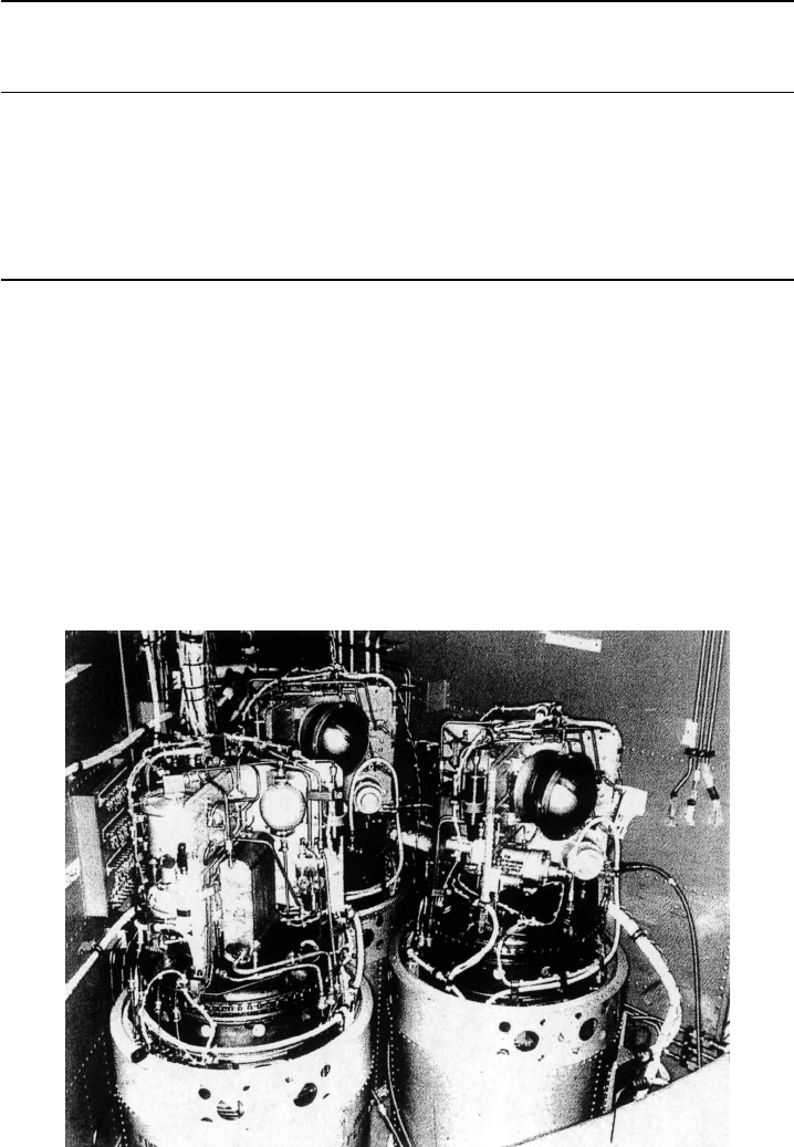
AFC enabled the use of non–noble metal nickel catalysts. The Gemini space program in
the United States utilized a PEFC, but the Apollo program (Figure 7.24) and early Space
Shuttles used AFCs to generate auxiliary power and potable water [56]. Future Space Shuttle
systems will apparently utilize PEFCs for auxiliary power [57]. In the Apollo system, the
sintered nickel electrodes were augmented with up to 40 mg/cm
2
platinum (cost was not an
issue for the Apollo program) to increase performance, despite reduced operation pressure.
The AFCs have also been developed for military applications, including the Swedish and
German navies, Russian aerospace applications, and power generation by Siemens [58].
Figure 7.24 Cluster of three 1.5-kWe (maximum 2.3-kWe) AFC units used on NASA Apollo
program. (Reproduced with permission from Ref. [58].)
c07 JWPR067-Mench December 19, 2007 17:46 Char Count=
7.4 Alkaline Fuel Cells 413
For automotive use, an array of thirty-two 5-kWe AFCs were constructed by Union Carbide
and used for propulsion in a General Motors six-passenger van in 1967 [56]. Additionally, a
6-kWe hydrogen/air AFC was installed by K. Kordesch in a lead–acid dual-cell hybrid, and
actually ran on public roads for three years with a six-bottle array of compressed hydrogen
on the roof [56], using air that was run through a soda lime bed to remove CO
2
. Modern
AFCs now operate at nearly the same conditions as PEFCs, at slightly elevated pressures
(∼ 2 atm) and around 100
◦
C.
One of the major limitations of the AFC system is the inability to tolerate CO
2
, normally
found in air in levels of around 380 ppm (0.0383%) [59]. In industrialized areas or locations
with combustion activity, the local CO
2
concentration can be even greater. The CO
2
in the
air or in impure hydrogen reacts with the potassium hydroxide in the electrolyte to form
solid carbonate crystals through the following reaction [60]:
CO
2
+ 2KOH
(
aq
)
→ K
2
CO
3(s)
+ H
2
O (7.13)
The carbonate particle formation reduces ionic conductivity and can block pores of the
electrode, leading to reduced performance. Carbon dioxide intolerance can be managed
in three ways: (1) operation on pure oxygen and hydrogen, (2) use of CO
2
scrubbers to
eliminate CO
2
from the input stream, or (3) use of a recirculating electrolyte (discussed
below) to remove the carbonate from the electrolyte and avoid buildup. Operation on pure
reactants is really only feasible for aerospace applications where pure oxygen and hydrogen
are available as fuel for liquid rocket systems. However, the AFC can be coupled with an
electrolyzer system to create a reversible fuel cell, discussed in Chapter 1. Use of CO
2
scrubbers to eliminate the CO
2
from the air stream is not 100% efficient, and if using
hydrogen from reformer-based systems, scrubbing is also needed for the hydrogen feed
stream. The resulting equipment is expensive and adds to the bulk of the total system. A
recirculating electrolyte can be used to increase the CO
2
tolerance and lifetime of AFC
systems somewhat and is discussed later in this section.
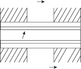
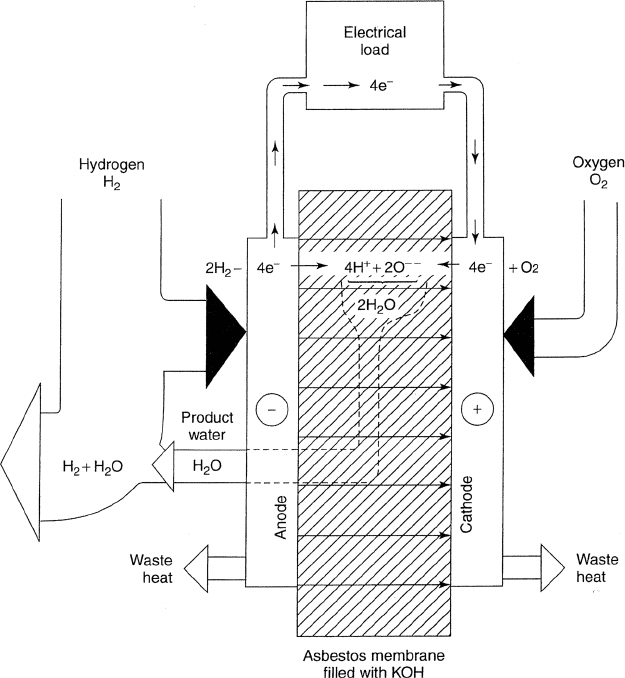
Electrolyte System The AFC can be categorized into two main configurations, static
electrolyte and mobile electrolyte systems. A schematic of the mobile electrolyte system
is shown in Figure 7.25. In this system, the electrolyte is pumped from the stack into
an electrolyte reservoir. The mobile electrolyte is constrained within the porous electrode
structure either by asbestos or other porous separation layer between the electrode and
the mobile electrolyte or by careful control of the differential pressure in the anode and
cathode and the surface tension in the porous electrode structure as in the MCFC and
PAFC liquid electrolyte systems. The use of a mobile electrolyte offers the following major
advantages:
1. Heat Management The electrolyte can be used as a coolant to remove heat from
the stack, eliminating the need for a separate coolant system. The electrolyte is
passed through a radiator upon leaving the stack.
2. Water Management The product water from the anode can be removed from the
system through an evaporator, reducing the parasitic flow requirements on the anode
and maintaining a proper water balance.
3. Electrolyte Poison Management The electrolyte is easily poisoned by small
amounts of CO
2
. Recirculation of the electrolyte can be used to filter and
c07 JWPR067-Mench December 19, 2007 17:46 Char Count=
414 Other Fuel Cells
Figure 7.25 Mobile recirculating electrolyte system in AFCs. Heat transfer, water removal, and
impurity removal occur through the flushed electrolyte. (Reproduced with permission from Ref. [58].)
remove carbonate particles that form as a result of CO
2
impurity. Alternatively,
the electrolyte can be completely flushed and replaced on a regular basis, given the
inexpensive nature of the KOH solution.
4. Electrolyte Gradient Management During operation, the electrolyte solution be-
comes concentrated (and possibly solidified) at the cathode and diluted at the anode
since water is generated at the anode and consumed at the cathode. This affects the
conductivity and vapor pressure of the electrolyte solution. Some of this gradient is
offset by water diffusion from the anode to the cathode. With a flowing electrolyte,
convective flow of the electrolyte minimizes these gradients.
c07 JWPR067-Mench December 19, 2007 17:46 Char Count=
7.4 Alkaline Fuel Cells 415
The major disadvantages of the recirculating electrolyte include the following:
1. The additional hardware and high-temperature pumps that are required to handle
the elevated temperature fluid, transfer heat, clean impurities, and remove vapor add
to the bulk and reduce the reliability of the system.
2. Since all the electrolyte between individual plates is connected in the AFC sys-
tem, there is a potential for internal short circuits that rob power. This is managed
by maximizing the electrolyte path length between individual cells, by combin-
ing cells in a mixed series–parallel arrangement to reduce the maximum voltage
potential.
3. The recirculating electrolyte is affected by changes in orientation and gravity unlike
a capillary-pressure based static system. In zero-gravity situations, such as the Space
Shuttle, the choice of static electrolytes is partially due to the capillary pressure
control of these systems.
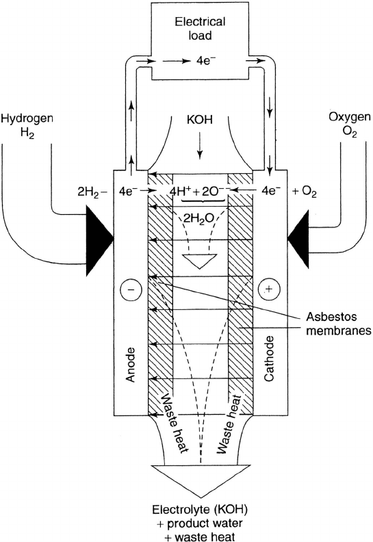
A schematic of the static electrolyte system is shown in Figure 7.26. In this config-
uration, an asbestos or other porous medium is soaked with the electrolyte solution and
maintained between the sintered metal or metal porous mesh electrodes. The advantages
of this approach are basically the opposite of the recirculating electrolyte system disadvan-
tages: The static system is more compact and simplified and does not suffer from internal
shorting of the electrolyte. However, the static system is almost certainly unsuitable for
operation on anything besides completely pure reactants, since CO
2
poisoning cannot be
remediated and damage will quickly accrue. Two other disadvantages of the static elec-
trolyte are heat and water management. A separate coolant fluid must be used in the static
system to remove water heat, and the water generated at the anode must be removed using
excess flow stiochiometry at the anode, which is parasitic.
A majority of terrestrial AFC applications use circulating electrolyte systems be-
cause operation on pure oxygen and hydrogen is not feasible, while space applications
demanding less bulk, more reliability, and zero-gravity operation use static electrolyte
systems.
Stack Configuration The individual cells in bipolar plate stacks such as the PEFC are
typically connected in series, with current collection across the entire electrode surface
along the interface between the bipolar plate landings and the DM. The flow fields in
AFCs are similar to those used in other fuel cells, and various parallel and serpentine
configurations are used to optimize mass, heat, and reactant/product transport.
A subset of stacks are designed using monopolar plates. Monopolar plates are used for
many AFC applications [61]. In this design, there is a PTFE sheet between the electrode and
the flow field to prevent the liquid electrolyte from passing through the electrode into the
channel, which can be by static forces or by weeping, which is caused by electro-osmotic
pressure-induced motion resulting from current flow. The PTFE coating also prevents
electrical conduction between the land–DM interface, and the current cannot pass from
the anode of one cell to the cathode of the adjacent cell through the flow field plate.
Therefore, the individual cells do not need to be connected completely in series, as in the
bipolar plate design stack. Instead, they are connected in a series–parallel arrangement to
optimize power, compactness, and durability. A monopolar arrangement allows the unique
advantage of isolating single cells in the event of replacement or damage as also realized
c07 JWPR067-Mench December 19, 2007 17:46 Char Count=
416 Other Fuel Cells
Figure 7.26 Static electrolyte system in AFCs. Heat transfer, water removal, and impurity removal
occur through the anode and cathode flows. (Reproduced with permission from Ref. [58].)
in SOFC bundle arrangements. In a series arrangement, if one cell is damaged, the entire
stack fails. Current collection from the electrode in the monopolar design occurs from a
metal current collector that frames and contacts the outside of the electrochemical active
area. Obviously, excellent current conduction along the electrode surface is needed to avoid
maldistribution of current and dead zones in the middle of the active area. As a result, this
approach is typically used only with metal mesh electrodes and small-area (<400-cm
2
)
AFCs [62].
Electrode Materials The AFCs developed by F. Bacon utilized nonnoble sintered nickel
metal catalysts. The high electrical conductivity of these porous electrodes permits use of
current collection from monopolar stack plates [62]. The sintered metal is often applied
in two separate layers, with large pores on the channel side, so that control of the liquid
electrolyte–gas phase interface can be achieved by capillary and gas-phase pressure forces.
c07 JWPR067-Mench December 19, 2007 17:46 Char Count=
7.4 Alkaline Fuel Cells 417
The use of Raney metals, which are physical mixtures of an active metal such as nickel
or silver with an inactive one such as aluminum, is another approach [26]. The aluminum
and active metal powder in Raney metals are not alloyed, and subsequent treatment with a
strong alkali solution dissolves the aluminum, leaving a porous active metal structure with
high electrical conductivity. The lower temperature modern AFCs mostly use noble metals
rather than nickel, although other spinels or perscovites can be used at the cathode with the
alkaline electrolyte [63].
Modern electrodes are similar to PEFC electrode structures with a porous carbon cloth
DM, consisting of a carbon support material with fine metal catalysts, interdispersed with
PTFE for hydrophobicity and pressed onto a nickel mesh to improve in-plane conductivity.
As discussed, to prevent electrolyte weeping loss into the channels, a thin layer of PTFE
is used to coat the electrode, and a monopolar design must be used. This is not a problem,
however, considering the nickel mesh used on the electrode surface permits the high
in-plane conductivity required to enable efficient current collection around the electrode
current-conducting frame.
7.4.2 Summary of Advantages and Disadvantages
Alkaline fuel cells are an older fuel cell technology, first seriously developed and ap-
plied in aerospace and naval applications, where cost was not much of a concern and
pure fuel and oxidizer were available. For a variety of reasons, development of this tech-
nology has almost ceased, but it may be revived in the future if a solution to the disad-
vantages of the system are found. The basic advantages of the AFC system include the
following:
1. The highest demonstrated operating efficiencies of any fuel cell system due to the
reduced polarization during the ORR compared to acid-based electrolytes.
2. Use of a low-cost electrolyte, potassium hydroxide (KOH).
3. Flexibility in the choice of operating conditions and use of nickel-based electrode
structures in high-temperature AFCs.
4. Inexpensive raw materials of the stack.
The main limitations which have hindered development of the AFC to date include the
following:
1. An intolerance to CO
2
, which forces the use of CO
2
removal equipment, pure
oxygen and hydrogen, or a recirculating electrolyte system that severely reduces
system energy density.
2. The need to manage water and electrolyte removal from the anode and electrolyte
solution, which complicates system design and control.
Development of AFC systems was undertaken by several major companies and research
organizations for over 40 years, with interest waning since the middle 1990s. Alkaline
fuel cells represent a low-cost, high-efficiency system that does not necessarily need noble
metal catalysts. Siemens developed AFC technology for over 20 years and made substantial
progress, only to ultimately abandon research efforts in favor of alternative technology [64].
c07 JWPR067-Mench December 19, 2007 17:46 Char Count=
418 Other Fuel Cells
Ultimately, because of the high efficiency on pure oxygen and hydrogen and the need
to run on pure reactants, the AFC is best suited for niche use in reversible fuel cell systems
or aerospace applications. However, the intrinsic advantage of reduced ORR losses with
an alkaline electrolyte will always remain attractive. A breakthrough in CO
2
tolerance,
aCO
2
-tolerant alkaline electrolyte with similarly good ORR kinetics, or cost-effective
CO
2
filtration would likely spur renewed interest. Some CO
2
tolerance is now possible
[65], so there may be a future for this technology. Development of alkaline-based polymer
electrolyte fuel cells is also a promising future technology.
7.5 BIOLOGICAL AND OTHER FUEL CELLS
Just when it seems all of the possible combinations of fuel cells have been examined, there
are more. In this section, a very brief description of some of the fuel cell concepts with
future potential is given as a brief introduction. Biological fuel cells, or biofuel cells, use
biological processes to convert organic fuel directly into electrons. A microbial biofuel
cell uses living microorganisms for the electrochemical reaction. Since the organisms are
living, the system is very sensitive to environmental changes which can quickly kill off
the microorganisms. Enzymatic biofuel cells utilize redox enzymes as biocatalysts for the
redox reactions. Bioprocessing of water products can also be used to directly generate
hydrogen for conventional fuel cells. The energy density of these bio-based systems is
several orders of magnitude lower than conventional fuel cell systems, however. Excellent
reviews and summaries of biofuel cells are given in [66–68].
Metal air batteries are sometimes referred to as fuel cells. Really, they are hybrid
systems that operate on flowing air like fuel cells but oxidation of stored metal like a
battery. Usually, an alkaline electrolyte is used in these system because of the favorable ORR
kinetics. Because the fuel is stored as a solid and the oxygen is not stored onboard, instead
absorbing from the ambient air during discharge, the system can achieve a higher specific
charge and energy density compared to full-battery systems. Essentially, this behaves as a
battery with the oxidizer stored in the ambient air. It is an energy storage system that does
not obtain a true equilibrium because the fuel is gradually depleting during discharge, and
therefore these are not really fuel cells. Reviews of zinc–air and seawater aluminum–air
systems can be found in [69, 70].
7.6 SUMMARY
The world of fuel cells comes in many varieties. Although PEFCs are featured in Chapter 6,
they are by no means the only option. Several other fuel cell systems can potentially reach
commercial production following current development trajectories. In a generic sense,
the advantages and disadvantages of each fuel cell fall along the lines of temperature
and electrolyte classification. High-temperature fuel cells suffer from reduced maximum
thermodynamic efficiency and slow startup times but can use non–noble metal catalysts and
reform a wide variety of carbon-based fuel streams, while low-temperature fuel cells can
have rapid startup but have higher raw material costs and a need for pure hydrogen streams.
All liquid electrolyte systems suffer from vaporization losses and enhanced corrosion.
c07 JWPR067-Mench December 19, 2007 17:46 Char Count=
Application Study: System Design 419
Individually, the first real development thrust was focused on the AFC for space
applications. The AFC has a broad temperature and pressure operation range and the
highest operating efficiency of the various fuel cell combinations due to the reduced ORR
polarization. However, its low power density and inability to handle CO
2
in air without a
scrubber or recirculating electrolyte configuration have limited its usefulness.
The PAFC was the next system to be seriously developed following the AFC and is
the first mass-produced fuel cell system to reach the consumer market in premium power
applications. Through several generations of design, stationary 200-kWe PAFC systems
showed reliable (>95%) service and high combined efficiency (>80%). Ultimately, the
total system cost has limited development of this technology.
Molten carbonate and solid oxide fuel cells are the high-temperature fuel cell technolo-
gies available. Both systems have the potential for direct internal reformation of carbon-
based fuel sources and used as part of a CHP or cogeneration system for achieving high
overall conversion efficiency. Issues with the liquid electrolyte loss and accelerated cata-
lyst and separator plate corrosion in the MCFC must be resolved, and SOFC systems will
continue to seek less expensive and more reliable manufacturing methods that increase
the stack component robustness. It is a desire of SOFC design to reach lower operating
temperatures approaching that of the MCFC (650
◦
C), so that metallic parts can be used.
This is being approached with anode-supported designs, novel electrolyte materials, and
ultrathin electrolyte structures.
There are also many other fuel cell technologies that are not yet mainstream but may
become mainstream in the future. Metal–air battery systems are really a hybrid between a
battery with stored fuel and a fuel cell with flowing oxidizer. Biological fuel cells represent
laboratory-based nascent technologies with very low power density. However, the potential
advantages of these systems for power neutral waste remediation is worthy of future
development.
It is a common misconception that no fuel cell system has been marketed as a product.
Many have, and more are coming. The high-temperature systems even eliminate the need for
a hydrogen infrastructure, so that implementation of stationary power applications can occur
right away. Given the high efficiency, low emission, and relatively silent operation of PAFC,
SOFC, and MCFC systems, it seems highly likely that at least one of these technologies
will be come mainstream for stationary power applications in the coming decades.
APPLICATION STUDY: SYSTEM DESIGN
The ancillary components in many fuel cell systems consume 50–75% of the cost and bulk
of the system, are responsible for many of the degradation issues, and can consume 20–30%
of the gross power output of the system. In this assignment, choose a fuel cell system (e.g.,
a molten carbonate fuel cell for stationary power applications) and draw a process flow
diagram of the system. Try to include all of the components necessary for operation,
including pumps, blowers, preheaters, and power conditioning. An example of a process
flow diagram for a 3-MWe molten carbonate fuel cell operating on landfill gas is given
below. On a separate page, list the function of each component you show. Make sure you
have not left anything out. Will the flow be able to come into and leave the stack? What will
happen to the unused fuel? Will the power be properly conditioned to suit the application?