Mench M.M. Fuel Cell Engines
Подождите немного. Документ загружается.


c07 JWPR067-Mench December 19, 2007 17:46 Char Count=
7
Other Fuel Cells
Finally, advances in technology are beginning to offer a way for
economies ...to diversify their supplies of energy and reduce their
demand for petroleum, thus loosening the grip of oil and the coun-
tries that produce it. ...The only long-term solution ...is to reduce
the world’s reliance on oil. Achieving this once seemed pie-in-the-
sky. No longer. Hydrogen fuel cells are at last becoming a viable
alternative. ...One day, these new energy technologies will toss
the OPEC cartel in the dustbin of history. It cannot happen soon
enough.
—“The End of the Oil Age,” editorial, The Economist,
October 25, 2003
At this point, the reader should be quite familiar with the basic operation of fuel cells, in
particular polymer electrolyte fuel cells (PEFCs). What is surprising for some to realize
is that PEFCs have only recently been considered to be the most logical choice for future
power. Several other fuel cell systems have been developed over the past century, including
proposed direct carbon conversion in solid oxide–based systems. Alkaline fuel cells (AFCs)
have been used for space and naval applications since the 1960s. Phosphoric acid fuel cells
(PAFCs) were fully developed into commercial systems for stationary power, with hundreds
of units sold to the public since the mid-1990s. Molten carbonate and solid oxide systems
also continue to be developed and, in stationary applications, offer unique advantages
compared to PEFCs. Other fuel cell systems, such as biological fuel cells, may become
viable in certain technological niches.
The question is often asked, what is the best fuel cell system and when will we see it?
The answer is simple: Like any commodity, the value and marketability must be compared
to the alternatives available. The best fuel cell for a particular purpose depends on the
application and the competing technologies. We will see the fuel cell introduced to the
public when it becomes a better alternative to the competing technologies. As long as there
are less expensive and more convenient alternatives, fuel cells will not be introduced in
large quantities.
The purpose of this chapter is to describe the development and operation of the var-
ious fuel cell systems besides the PEFC. With background information from Chapters
1–5, the reader should be able to fully appreciate and analyze the different designs, op-
erational advantages, and technical challenges of the other fuel cell varieties discussed.
380
Fuel Cell Engines
Copyright © 2008 by John Wiley & Sons, Inc.
Matthew M. Mench
c07 JWPR067-Mench December 19, 2007 17:46 Char Count=
7.1 Solid Oxide Fuel Cells 381
Although a brief summary of the history of these systems is given here, detailed histor-
ical summaries of the various fuel cell technology development can be found in many
resources.
7.1 SOLID OXIDE FUEL CELLS
Development History High-temperature solid oxide fuel cells (SOFCs) began with
Nernst’s 1899 demonstration of the ionic conductivity of solid-state yttria-stabilized zir-
conia (YSZ) [1], but significant practical application was not realized for a variety of
technical and practical reasons. Modern SOFC development has been revived worldwide,
as several companies in the Unites States, Europe, and Asia are competing to bring small
and large SOFC power systems to market. Development is on going 1–5-kW units for
auxiliary electrical power (not propulsion) by BMW and Delphi [2] and for cogenera-
tion and auxiliary distributed power by Siemens (formerly Siemens-Westinghouse). In
2006, Mitsubishi Heavy Industries demonstrated Japan’s first SOFC-micro gas turbine
combined-cycle power generation system. The 75-kW system achieved power generation
efficiency above 50%, significantly higher than conventional systems, and plans for a
200-kWe system are underway [3]. Rolls Royce Fuel Cell Systems (RRFCS) has been
developing SOFC technology since 1995, focusing on cogeneration hybrid power plant
technology using low-cost screen-printing manufacturing techniques [4]. Australian-based
Ceramic Fuel Cells Unlimited (CFCL) has developed 1-kWe combined heat and power
(CHP) flat-plate SOFC technology called NetGen, with an electrical efficiency of ∼40%
and a combined efficiency of ∼80% [5]. Many other companies and research laboratories
are also conducting intense research and development, and journal publications and patent
literature should be consulted for the latest developments. Despite the high operating tem-
peratures, there is even research and development of compact power systems for portable
applications. Lilliputian Systems is developing hand-held SOFC units for portable power
applications [6]. In the United States, there has been much SOFC development incubated
by the Department of Energy Solid State Energy Conversion Alliance (SECA) program.
The 10-year goal of the SECA program is to develop kilowatt-sized SOFC APU units at
$400/kW by 2010. By 2005, some systems developed under this program already reached
$746/kW [7].
7.1.1 Operation and Configurations
The SOFC and molten carbonate fuel cell (MCFC) represent high-temperature fuel cell
systems. The SOFC avoids some of the major disadvantages of the high-temperature MCFC,
however, since the electrolyte is a solid ceramic and therefore not prone to corrosion or
evaporative loss as observed in liquid electrolyte systems. The current operating temperature
of most SOFC systems is around 800–1000
◦
C, although new technology has demonstrated
600
◦
C operation, where vastly simplified system sealing and metallic materials solutions are
feasible. The desire for lower temperature operation of the SOFC is ironically opposite to
the PEFC, where higher operating temperature is desired to simplify water management and
CO poisoning issues. Reduced temperature operation would enable more rapid startup and
use of common metallic compounds for cell interconnects, reduce thermal stresses, reduce
c07 JWPR067-Mench December 19, 2007 17:46 Char Count=
382 Other Fuel Cells
the rate of some modes of degradation, and increase reliability with lowered manufacturing
costs. Despite the technical challenges, the SOFC system is a good potential match for
many applications, including stationary cogeneration plants and auxiliary power.
The high operating temperature of the SOFC requires long startup time to avoid
damage due to nonmatched thermal expansion properties of materials. Another temperature-
related limitation is that no current generation is possible until a critical temperature is
reached in the solid-state electrolyte, where oxygen ionic conductivity of the electrolyte
becomes nonnegligible, as shown in Chapter 5. Commonly used electrolyte conductivity
is nearly zero until around 650
◦
C [8], although low-temperature SOFC operation at 500
◦
C
using doped ceria (CeO
2
) ceramic electrolytes with anode support materials has shown
feasibility [9]. Many other electrolyte and electrolyte structures have potential for even
lower temperature operation [10, 11].
In many system designs, a combustor is utilized to preheat the fuel cell during warmup
and to burn fuel and oxidizer effluent to provide a source of heat for cogeneration. The
poststack combustor can effectively eliminate effluent residual hydrogen and CO, which is
especially high during startup when fuel cell performance is low. It is especially important
during start-up and shut-down transients that electrolyte, electrode, and current collector
materials have matched thermal expansion properties to avoid internal stress concentrations
and damage.
The solid-state, high-temperature SOFC system eliminates many of the technical chal-
lenges of the PEFC while suffering unique limitations. In general, a SOFC system is well
suited for applications where a high operating temperature and a longer startup transient
are not limitations or where conventional fuel feedstocks are desired. The elevated temper-
ature of operation means that high-quality waste heat is available for cogeneration systems.
Besides manufacturing and economic issues beyond the scope of this section, the main
technical limitations of the SOFC include thermal management, manufacturing processes,
material design, startup, durability, and, in some designs, cell-sealing problems resulting
from mismatched thermal expansion of materials. For additional details, an excellent text
devoted to the SOFC was written by Minh and Takahashi [8].
The manufacturing methods for the SOFC structure are critical components in the
ultimate cost of the system. Methods are diverse and vary depending on the cell design
and manufacturer. Methods of SOFC production can include evaporative deposition, ex-
trusion, tape casting, screen printing, plasma spraying, wet powder spraying, sintering,
electrophoretic deposition, and vacuum slip casting. For details on these processes, the
reader is referred to ref. [12, 13]. Manufacturing of these cells is a critical challenge, as
a significant fraction of manufactured cells are not useful due to thermal stress related
damage, increasing cost.
A schematic of the basic materials and electrochemical reactions of the SOFC is
given in Figure 7.1. In the SOFC system, yttria- (Y
2
O
3
) stabilized zirconia (ZrO
2
)ismost
often used as the electrolyte, although many other combinations are continually evaluated
[14]. In this solid-state electrolyte, O
2−
ions are passed from the cathode to the anode
via oxygen vacancies in the electrolyte as described in Chapter 5. Other cell components
such as interconnects and bipolar plates are typically doped ceramic, cermet, or metallic
compounds.
The conductivity of the electrolyte, electrodes, and interconnects normally dominates
cell losses. Because of a desire to achieve high power density, the individual layers in the
SOFC should be made as thin as possible. However, if they are too thin, the brittle materials
c07 JWPR067-Mench December 19, 2007 17:46 Char Count=
7.1 Solid Oxide Fuel Cells 383
Anode - Nickel on YSZ
Cathode - Strontium-doped lanthanum manganite
Electrolyte - Yttria stabilized zirconia
O
2-
H
2
+ O
2-
H
2
O + 2e
-
O
2
+ 4e
-
2O
2-
Cell-to-cell interconnect - Metals or ceramics
Figure 7.1 Schematic of materials and reactions occurring in a SOFC.
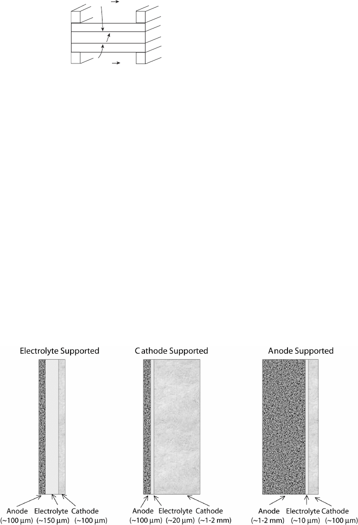
will crack and break under their own weight. Therefore, an electrode-, cathode-, or anode-
supported design is used, as shown in Figure 7.2. In the case of a cathode-supported design,
the main limitation is cathode electrode polarization, since the thick cathode prohibits
oxygen diffusion. Also, thermal mismatch between the thin anode can lead to damaging
delamination stresses. In the anode-supported design, the stresses generated by the nickel
anode, which expands more than other materials under increased temperature, creates
vertical cracks in the electrode structure, which can actually facilitate hydrogen diffusion.
Since hydrogen diffusion is so much more rapid than oxygen diffusion and an electrolyte-
supported design results in very high ohmic losses, an anode-supported design is generally
favored [15], especially to achieve lower operating temperatures, since the ohmic loss
is proportional to the layer thickness [16]. Some designs use an inert porous supporting
structure and eliminate the need for a thick electrode or electrolyte altogether.
Unlike most other fuel cells, water is produced at the anode of the SOFC (and MCFC).
Additionally, instead of being a poison, CO can act as a fuel in the SOFC through the
following anodic reaction:
CO + H
2
O → CO
2
+ H
2
(7.1)
Figure 7.2 Schematic of anode-, cathode-, or electrolyte-supported design and related typical
thicknesses. (Adapted from [15].)
c07 JWPR067-Mench December 19, 2007 17:46 Char Count=
384 Other Fuel Cells
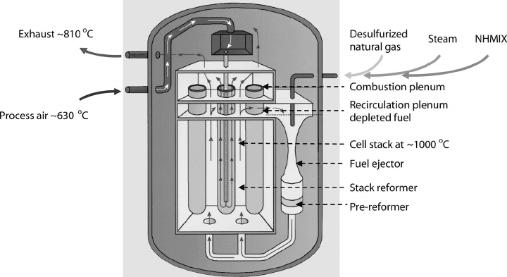
Figure 7.3 SOFC stack with pre-reforming zones before fuel introduction into main reacting cells.
(Image courtesy of Siemens Power Generation.)
Thus, CO, a minor species product of fuel reformation and a major poison to PEFCs, can
actually be used as a fuel. In practice, this means that use of reformed gas without any
CO cleanup is perfectly acceptable directly at the anode. The high temperature, anodic
water production, and CO tolerance are some of the distinct advantages of the SOFC
because they allow for direct steam reformation of a wide variety of fuel gases, eliminating
the need for pure hydrogen feed and associated infrastructure. Reforming is discussed in
Chapter 8, but a brief introduction is given here. When a carbon-containing fuel is steam
reformed, the carbon is reacted with oxygen and water to form carbon dioxide, hydrogen,
and carbon monoxide. This type of reforming is an endothermic process. The ratio of
carbon dioxide to carbon monoxide depends on the temperature, pressure, and the amount
of steam present. For methane, reformation can occur above 600
◦
C, well within the range
of SOFC operating temperatures. The reformation process can take place external to the
fuel cell using waste heat and product steam for the endothermic process, or internal to the
fuel cell. Internal reformation can be accomplished inside the stack in special reformer cells
before the incoming anode fuel gas, as shown in Figure 7.3. Direct internal reformation
can also be accomplished by injecting the untreated fuel gas directly into the reaction zone.
Although this is potentially space and cost saving, it can lead to accelerated degradation of
the anode catalysts and material compatibility problems. Since the reformation reaction is
endothermic, the local temperature at the inlet of the reformer zone can drastically decrease,
causing thermal stresses which result in catastrophic damage. Additionally, undesired minor
species such as carbon can foul the electrode surface. Control of the temperature distribution
in SOFCs is an important engineering design aspect for several reasons: (1) Since the
performance is dominated by the conductivity of the materials, which are directly related
to the temperature, the temperature distribution dominates the current distribution, and (2)
internal thermal stresses should be minimized to avoid cell damage and promote good
sealing.

c07 JWPR067-Mench December 19, 2007 17:46 Char Count=
7.1 Solid Oxide Fuel Cells 385
High electrolyte temperature is required to ensure adequate ionic conductivity (of O
2−
)
in the solid-phase ceramic electrolyte
1
which reduces activation polarization so much that
cell losses are typically dominated by internal cell ohmic resistance through the electrolyte
material. Typical SOFC open-circuit cell voltages are around 1 V, very close to the theo-
retical maximum, and operating current densities vary greatly depending on design. While
the theoretical maximum efficiency of the SOFC is less than the H
2
PEFC because of
increased temperature, activation polarization is extremely low. Operating efficiencies as
high as 60% have been attained for a 220-kWe cogeneration system [17], which compare
well to gas-turbine based cogeneration systems for stationary power.
SOFC Designs Perhaps no other type of fuel cell has more variety of cell and stack designs
than the SOFC. The problems of thermal mismatch and dominance of ohmic losses have
resulted in very innovative solutions. There are several different basic design classifications
for the SOFC system: the planar, sealless tubular, monolithic, and segmented cell-in-series
designs. Two of the designs, planar and tubular, are the most promising for continued
development. The other designs have been comparatively limited in development to date.
Planar Design The planar configuration looks geometrically similar to the planar
PEFCs and can be fitted with internal or external manifold systems. The three-layer
anode–electrolyte–cathode structure can be an anode-, cathode-, or electrolyte-supported
design (see Figure 7.2). Since excessive ionic and concentration losses result from
electrolyte- and cathode-supported structures, respectively, many designs utilize an anode-
supported structure, although ribbed supports or cathode-supported designs are utilized in
some cases.
For the planar design, the flow channel material structure is used as support for the
electrolyte, and a stacking arrangement is employed. Although this design is relatively
simple to manufacture, one of the major limitations is difficulty sealing the flow fields
at the edges of the fuel cell. Sealing is a key issue in planar SOFC design because it is
difficult to maintain system integrity over the large thermal variation and reducing/oxidizing
environment over many startup and shutdown load cycles. Compressive, glass, cermet,
glass–ceramic, and hybrid seals have been used with varied success for this purpose. As the
stack heats, the volume and sealing surfaces will move significantly, making any sealing
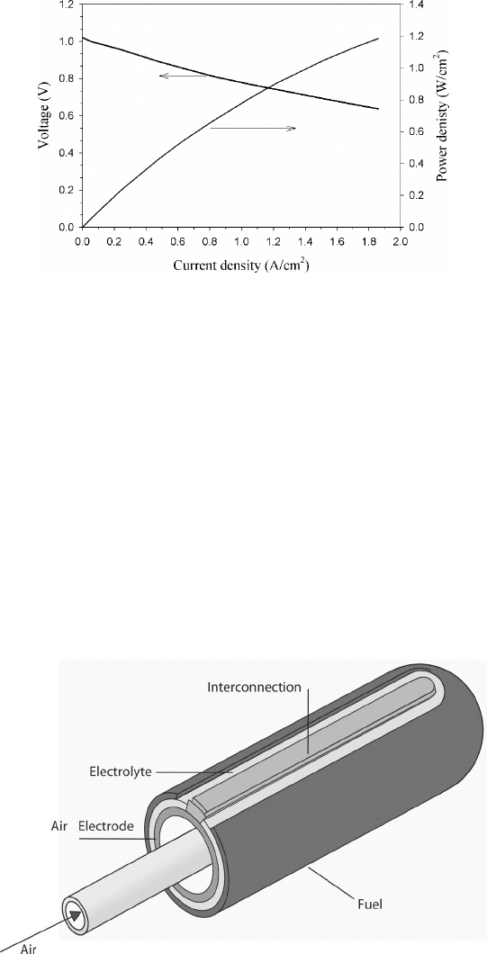
difficult, especially for the highly diffusive hydrogen. Planar designs can achieve a much
higher power density than the tubular designs (up to 2 W/cm
2
), opening the door to auxiliary
power applications [18]. A plot of a typical polarization curve for an anode-supported planar
SOFC is given in Figure 7.4.
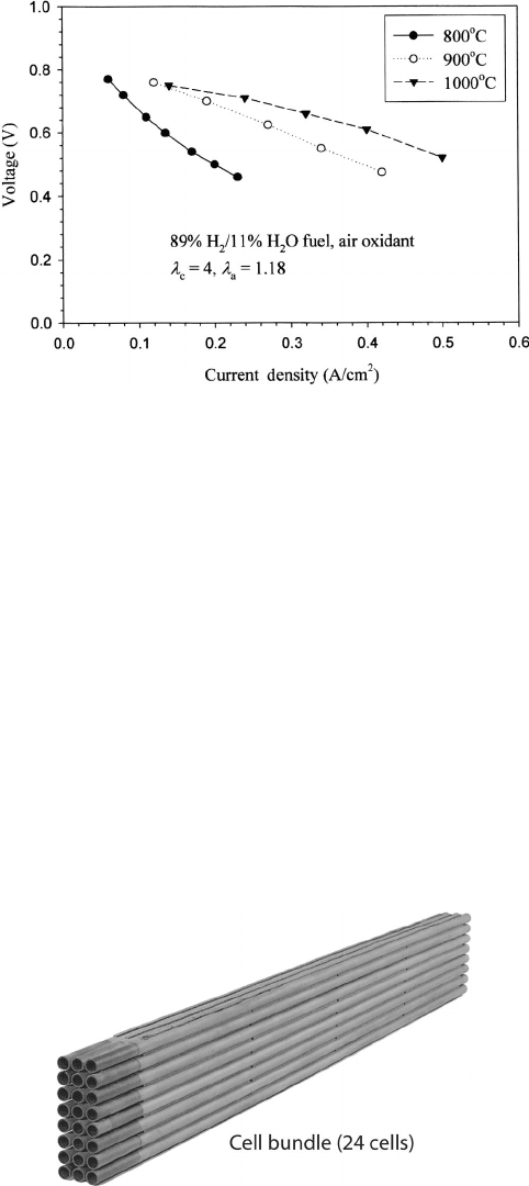
Sealless Tubular Design The second major design is the sealless tubular concept pio-
neered by Westinghouse (which became Siemens-Westinghouse and is now Siemens) in
1980. A schematic of the general design concept is shown in Figure 7.5. Air is injected
axially down the center of the fuel cell, which provides preheating of the air to operation
temperatures before exposure to the cathode. The oxidizer is provided at adequate flow
rates to 1) ensure negligible concentration polarization at the cathode exit, 2) to maintain
desired cell temperature, and 3) to provide adequate oxidizer for effluent combustion with
unused fuel. The major advantage of the tubular configuration is that the high-temperature
1
Relationships for ohmic losses in the YSZ were given in Chapter 5.
c07 JWPR067-Mench December 19, 2007 17:46 Char Count=
386 Other Fuel Cells
Figure 7.4 Performance of anode-supported planar SOFC at 800
◦
C. (Adapted from Ref. [16].)
seals needed for the planar SOFC design are eliminated. Tubular designs have been tested in
100-kWe atmospheric pressure and 250-kWe pressurized demonstration systems with little
performance degradation (less than 0.1% per 1000 h) and conversion efficiencies of 46 and
57% (LHV), respectively [19]. A polarization curve at various temperatures from a tubular
SOFC is shown in Figure 7.6. A 24-stack bundle and integrated SOFC system layout are
shown in Figures 7.7 and 7.3, respectively. In this bundle, rows of tubes are connected in
parallel, and columns in series. In contrast to a completely series stack commonly used
in PEFCs, this series–parallel arrangement is highly useful for system service durability.
In this configuration, individual cells can suffer catastrophic damage, and the stack does
not have to go offline, since the current is redistributed through other cells in parallel along
the bundle. This allows simplified maintenance and individual tube replacement without
suffering sudden catastrophic failure of the stack power, which is a major advantage.
Figure 7.5 Schematic of sealless tubular SOFC design. (Image courtesy of Siemens Power Gener-
ation.)
c07 JWPR067-Mench December 19, 2007 17:46 Char Count=
7.1 Solid Oxide Fuel Cells 387
Figure 7.6 Voltage–current density plots of typical 2.2-cm-diameter tubular SOFC cell. (Adapted
from [16].)
One drawback of this type of tubular design is the more complex and limited range
of cell fabrication methods. Another drawback is high internal ohmic losses relative to
the planar design, due to the relatively long in-plane path that electrons must travel along
the electrodes to and from the cell interconnect. Some of these additional ionic transport
losses have been reduced by use of a flattened tubular SOFC design with internal ribs
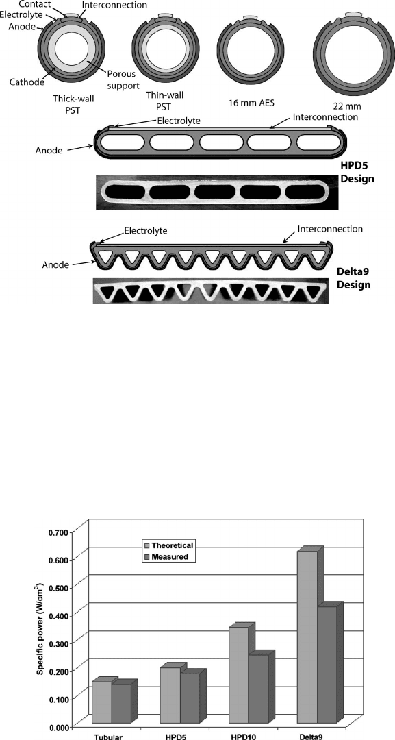
for current flow, called the high-power-density (HPD) design by Siemens [12, 16]. The
evolution of the tubular cell design and performance at Siemens is shown in Figures 7.8 and
7.9, respectively. The triangular Delta9 design has 300% higher power density and 60%
higher gravimetric power density than the pure tubular design [20]. This design can also
experience significant losses due to limited oxygen transport through the porous (∼35%
porosity) structural support tube used to provide rigidity to the assembly. The internal
tube can also be used as the anode, reducing these losses through the higher diffusivity of
hydrogen. Purely tubular cells have a power density at 1000
◦
C of about 0.25–0.30 W/cm
2
,
Figure 7.7 SOFC tubular stack bundle. (Image courtesy of Siemens Power Generation.)
c07 JWPR067-Mench December 19, 2007 17:46 Char Count=
388 Other Fuel Cells
Figure 7.8 Evolution of SOFC design at Siemens. (Image courtesy of Siemens Power Generation.)
in comparison to power densities of planar SOFCs, which can reach about 2 W/cm
2
[18].
Flattened cells reduce this gap between tubular and planar designs considerably.
In-Plane Design Another design concept for SOFCs is the in-plane fuel cell. This concept
is similar to the in-plane stack design proposed for use with DMFCs for portable applications
discussed in Chapter 6. The ion path length through the electrolyte is minimzed with this
design but is still longer than the planer design, increasing ohmic drop. Mechanical support
for the electrolyte comes from a porous fuel-side flat plate. Power output from this design
Figure 7.9 Evolution of SOFC design polarization behavior at Siemens, Statistics at 1000
◦
C, 0.65
V operation. (Image courtesy of Siemens Power Generation.)
c07 JWPR067-Mench December 19, 2007 17:46 Char Count=
7.1 Solid Oxide Fuel Cells 389
Figure 7.10 Schematic of monolithic SOFC design. (Image courtesy of Siemens Power Genera-
tion.)
is reported to be greater than 0.5 W/cm
2
at 950
◦
C, which compares favorably to tubular
designs but is less than the best planar designs.
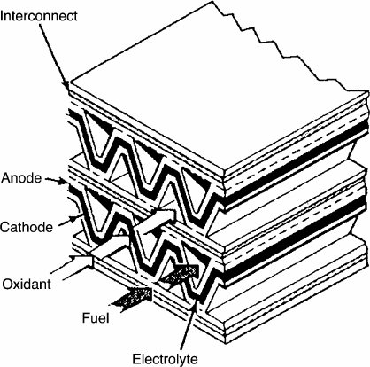
Other Designs The monolithic and segmented cell-in-series designs are less developed,
although demonstration units have been constructed and operated. A schematic of the
monolithic cell design is shown in Figure 7.10. In the early 1980s, the corrugated monolithic
design was developed, based on the advantage of high power density compared to other
designs. The high power density of the monolithic design is a result of the high active
area exposed per volume and the short ionic paths through the electrolyte, electrodes,
and interconnects. The primary disadvantage of the monolithic SOFC design, preventing
its continued development, is the complex manufacturing process required to build the
corrugated system. The Delta9 configuration of Figure 7.8 is close to a corrugated design
and combines the assembling advantages of the tabular design with the power density
advantages of the corrugated design.
The segmented-cell-in-series design has been successfully built and demonstrated in
two configurations: the bell-and-spigot and the banded configuration shown schematically
in Figure 7.11. The bell-and-spigot configuration uses stacked segments with increased
electrolyte thickness for support. Ohmic losses are high because electron motion is along
the plane of the electrodes in both designs, requiring short individual segment lengths
(∼1–2 cm). The banded configuration avoids some of the high ohmic losses of the bell-and-
spigot configuration with a thinner electrolyte but suffers increased mass transport losses
associated with the porous support structure used. The main advantage of the segmented-
cell design is a higher operating efficiency than larger area single-electrode configurations.
The primary disadvantages limiting development of the segmented-cell designs include
the necessity for many high-temperature gas-tight seals, relatively high internal ohmic
losses, and requirement for manufacture of many segments for adequate power output.