Pump Handbook by Igor J. Karassik, Joseph P. Messina, Paul Cooper, Charles C. Heald - 3rd edition
Подождите немного. Документ загружается.


8.34 CHAPTER EIGHT
(16)
where f friction factor
L pipe length, ft (m)
D inside pipe diameter, ft (m)
V average pipe velocity, ft/s (m/s)
g acceleration of gravity, 32.17 ft/s
2
(9.807 m/s
2
)
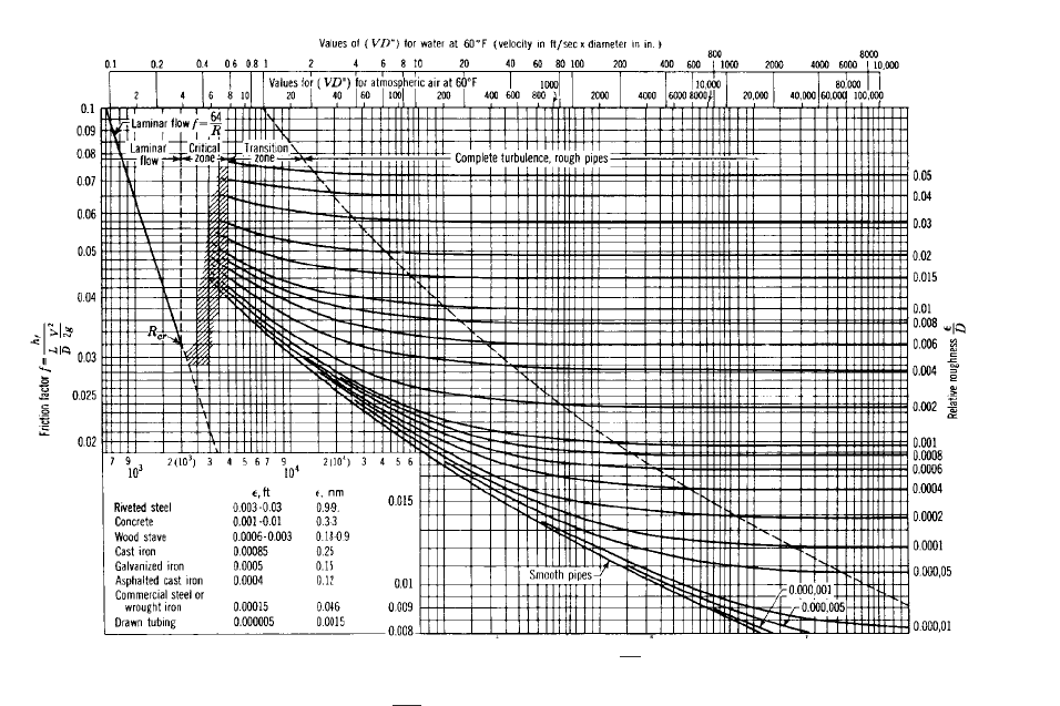
For laminar flow, the friction factor f is equal to 64/Re and is independent of pipe wall
roughness. For turbulent flow, f for all incompressible fluids can be determined from the
well-known Moody diagram, shown in Figure 31. To determine f, it is required that the
Reynolds number and the relative pipe roughness be known. Values of relative roughness
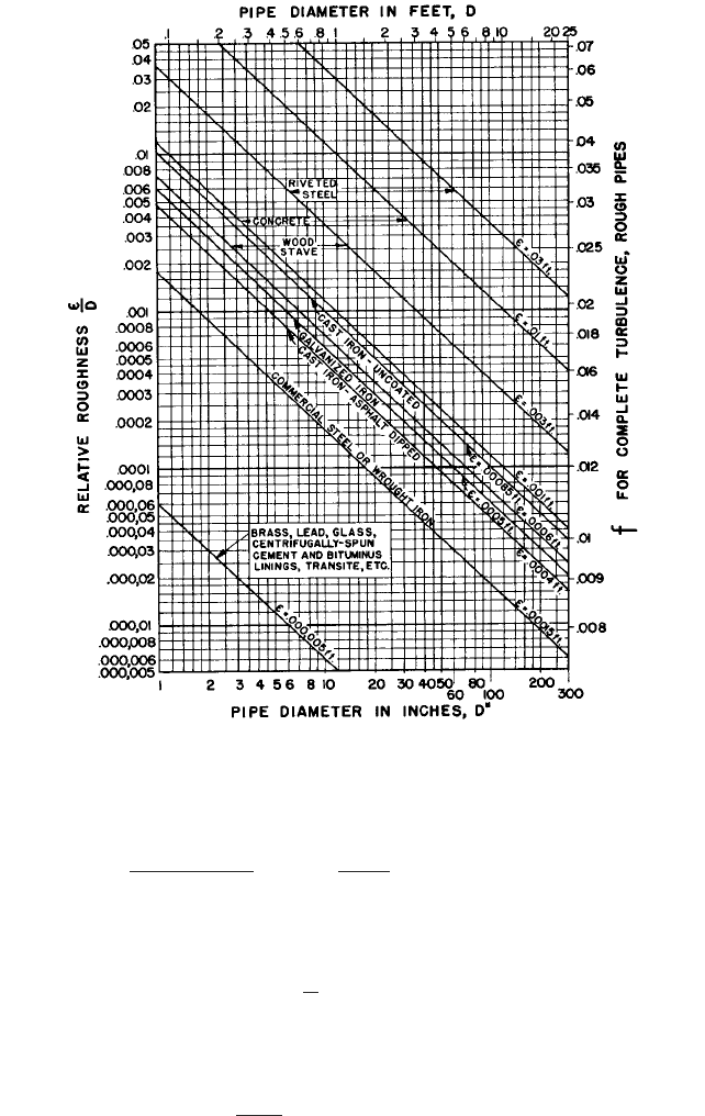
/D), where is a measure of pipe wall roughness height in feet (meters), can be obtained
from Figure 32 for different pipe diameters and materials. Figure 32 also gives values for
f for the flow of 60°F (15.6°C) water in rough pipes with complete turbulence. Values of
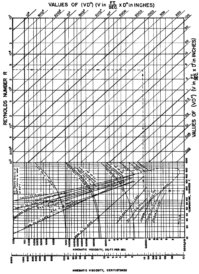
kinematic viscosity and Reynolds numbers for a number of different liquids at various
temperatures are given in Figure 33. The Reynolds numbers of 60°F (15.6°C) water for
various velocities and pipe diameters may be found by using the VD" scale in Figure 31.
There are many empirical formulas for calculating pipe friction for water flowing under
turbulent conditions. The most widely used is the Hazen-Williams formula:
In USCS units (17a)
In SI units (17b)
where V average pipe velocity, ft/s (m/s)
C friction factor for this formula, which depends on roughness only
r hydraulic radius (liquid area divided by wetted perimeter) or D/4 for a full
pipe, ft (m)
S hydraulic gradient or frictional head loss per unit length of pipe, ft/ft (m/m)
The effect of age on a pipe should be taken into consideration when estimating the fric-
tional loss. A lower C value should be used, depending on the expected life of the system.
Table 2 gives recommended friction factors for new and old pipes.A value of C of 150 may
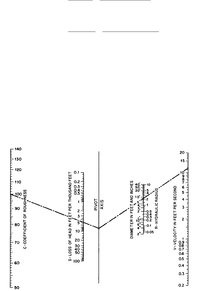
be used for plastic pipe. Figure 34 is a nomogram that can be used in conjunction with
Table 2 for a solution to the Hazen-Williams formula.
The frictional head loss in pressure pipes can be found by using either the Darcy-
Weisbach formula (Eq. 16) or the Hazen-Williams formula (Eq. 17). Tables in the appen-
dix give Darcy-Weisbach friction values for Schedule 40 new steel pipe carrying water.
Tables are also provided for losses in old cast iron piping based on the Hazen-Williams for-
mula with C 100. In addition, values of C for various pipe materials, conditions, and
years of service can also be found in the appendix.
The following examples illustrate how Figures 31, 32, and 33 and Table 2 may be used.
EXAMPLE 5 Calculate the Reynolds number for 175°F (79.4°C) kerosene flowing
through 4-in (10.16-cm), Schedule 40, 3.426-in (8.70-cm) ID, seamless steel pipe at a
velocity of 14.6 ft/s (4.45 m/s).
In USCS units
In SI units VD 4.45 0.087 0.387 m>s m 0.387 129.2 50 ft>s in
VD– 14.6 3.426 50 ft>s in
V 0.8492Cr
0.63
S
0.54
V 1.318Cr
0.63
S
0.54
h
f
f
L
D
V
2
2g
8.35
[[A 5655]]
FIGURE 31 Moody diagram. (Reference 14) In SI units: ( in kg /m
3
, V in m/s, D in m, µ in N
•
s/m
2
.) 1 meter 3.28 ft; 1VD (V in m/s, D in m)
129.2 VD– (V in ft/s, D– in inches).
R
rVD
m
Reynolds number consistent unitsR
VD
n

8.36 CHAPTER EIGHT
TABLE 2 Values of friction factor C to be used with the Hazen-Williams formula in
Figure 34
Type of pipe Age Size, in
a
C
Cast iron New All sizes 130
5 years old 12 and over 120
8 119
4 118
10 years old 24 and over 113
12 111
4 107
20 years old 24 and over 100
12 96
489
30 years old 30 and over
16 87
475
40 years old 30 and over 83
16 80
464
40 and over 77
24 74
455
Welded steel Any age, any size Same as for cast
iron pipe
5 years old
Riveted steel Any age, any size Same as cast
iron pipe
10 years older
Wood-stave Average value, regardless of age and size 120
Concrete or Large sizes, good workmanship, steel forms 140
concrete- Large sizes, good workmanship, wooden forms 120
lined Centrifugally spun 135
Vitrified In good condition 110
a
In 25.4 mm
Source: Adapted From Reference 15.
Follow the tracer lines in Figure 33 and read directly:
EXAMPLE 6 Calculate the frictional head loss for 100 ft (30.48 m) of 20-in (50.8-cm),
Schedule 20, 19.350-in (49.15-cm) ID, seamless steel pipe for 109°F (42.8°C) water flow-
ing at a rate of 11,500 gpm (2612 m
3
/h). Use the Darcy-Weisbach formula.
In USCS Units
VD– 12.53 19.35 242 ft>s in
V
gpm
1pipe ID in inches2
2
0.408
11,500
19.35
2
0.408 12.53 ft>s
Re 3.5 10
5
8.1 PUMPING SYSTEMS AND SYSTEM-HEAD CURRVES 8.37
FIGURE 32 Relative roughness and friction factors for new, clean pipes for flow of 60°F (15.6°C) water
(Hydraulic Institute Engineering Data Book, Reference 5) (1 meter 39.37 in 3.28 ft).
In SI units
From Figure 33
From Figure 32
From Figure 31
Using Eq. 16,
In USCS units D
19.35
12
1.61 ft
f 0.012
D
0.00009
Re 3 10
6
VD 3.83 0.4915 1.88 m>s m 1.88 129.2 242 ft>s in
V
m
3
>h
1pipe ID in cm2
3.54
2612
49.15
2
3.54 3.83 m>s
8.38 CHAPTER EIGHT
FIGURE 33 Kinematic viscosity and Reynolds number. (Hydraulic Institute Engineering Data Book, Ref.erence 5)
[1 ft
2
/s 0.0929 m
2
/s; 1 cSt 1.0 10
6
m
2
/s; 1VD (m/s m) 129.2 VD" (ft/s in); °F (°C 18) 1.8]

8.1 PUMPING SYSTEMS AND SYSTEM-HEAD CURRVES 8.39
In SI units
EXAMPLE 7 The flow in Example 6 is increased until complete turbulence results.
Determine the friction factor f and flow.
From Figure 31, follow the relative roughness curve e/D 0.00009 to the beginning
of the zone marked “complete turbulence, rough pipes” and read
The problem may also be solved using Figure 32. Enter relative roughness e/D
0.00009 and read directly across to
An increase in Re from 3 10
6
to 2 10
7
would require an increase in flow to
in USCS units
in SI units
EXAMPLE 8 The liquid in Example 6 is changed to water at 60°F (15.6°C). Determine
Re, f, and the frictional head loss per 100 ft (100 m) of pipe.
(as in Example 6)
Because the liquid is 60°F (15.6°C) water, enter Figure 31 and read directly down-
ward from VD– to
Where the line VD– to Re crosses e/D 0.00009 in Figure 31, read
Water at 60°F (15.6°C) is more viscous than 109°F (42.8°C) water, and this accounts for
the fact that Re decreases and f increases. Using Eq. 16, it can be calculated that the
frictional head loss increases to
in USCS units
in SI units
EXAMPLE 9 A 102-in (259-cm) ID welded steel pipe is to be used to convey water at a
velocity of 11.9 ft/s (3.63 m/s). Calculate the expected loss of head due to friction per
1000 ft and per 1000 m of pipe after 20 years. Use the empirical Hazen-Williams formula.
From Table 2, C 100.
In USCS units
In SI units r
D
4
2.59
4
0.648 m
r
D
4
102
14 122
2.13 ft
h
f
f
L
D
V
2
2g
0.013
100
0.4915
3.83
2
2 9.807
1.97 m
h
f
f
L
D
V
2
2g
0.013
100
1.61
12.53
2
2 32.17
1.97 ft
f 0.013
Re 1.8 10
6
VD– 242 ft>s in
2 10
7
3 10
6
2612 17,413 m
3
>h
2 10
7
3 10
6
11,500 76,700 gpm
f 0.0119
f 0.0119 at Re 2 10
7
h
f
f
L
D
V
2
2g
0.012
30.48
0.4915
3.83
2
2 9.807
0.556 m
h
f
f
L
d
V
2
2g
0.012
100
1.61
12.53
2
2 32.17
1.82 ft
8.40 CHAPTER EIGHT
FIGURE 34 Nomogram for the solution of the the Hazen-Williams formula. Obtain values for C from Table 2.
(Reference 15) (1 m/s 3.28 ft/s; 1 m 39.37 in)
Substituting in Eq. 17,
in USCS units
in SI units
The problem may also be solved by using Figure 34, following the trace lines:
Frictional Loss for Viscous Liquids Table 3 gives the frictional loss for viscous liq-
uids flowing in new Schedule 40 steel pipe. Values of pressure loss are given for both lam-
inar and turbulent flows.
For laminar flow, the pressure loss is directly proportional to the viscosity and the
velocity of flow and inversely proportional to the pipe diameter to the fourth power. There-
fore, for intermediate values of viscosity and flow, obtain the pressure loss by direct inter-
h
f
5 ft 1m2
h
f
1000 0.0048 4.8 m
S 10.05622
1>0.54
0.0048 m>m
S
0.54
V
0.8492Cr
0.63
3.63
0.8492 100 0.648
0.63
0.0562
h
f
1000 0.0048 4.8 ft
S 10.05572
1>0.54
0.0048 ft>ft
S
0.54
V
1.318Cr
0.63
11.9
1.318 100 2.13
0.63
0.0557

8.1 PUMPING SYSTEMS AND SYSTEM-HEAD CURRVES 8.41
polation. For pipe sizes not shown, multiply the fourth power of the ratio of any tabulated
diameter to the pipe diameter wanted by the tabulated loss shown. The flow rate and vis-
cosity must be the same for both diameters.
For turbulent flow and for rates of flow and pipe sizes not tabulated, the following pro-
cedures may be followed. For the viscosity and pipe size required, an intermediate flow loss
is found by selecting the pressure loss for the next lower flow and multiplying by the
square of the ratio of actual to tabulated flow rates. For the viscosity and flow required, an
intermediate pipe diameter flow loss is found by selecting the pressure loss for the next
smaller diameter and multiplying by the fifth power of the ratio of tabulated to actual
inside diameters.
The viscosity of various common liquids can be found in tables in the appendix.
Partially Full Pipes and Open Channels Another popular empirical equation applic-
able to the flow of water in pipes flowing full or partially full or in open channels is the
Manning formula:
In USCS units (18a)
In SI units (18b)
where V average velocity, ft/s (m/s)
n friction factor for this formula, which depends on roughness only
r hydraulic radius (liquid area divided by wetted perimeter), ft (m)
S hydraulic gradient or frictional head loss per unit length of conduit, ft/ft (m/m)
The Manning formula nomogram shown in Figure 35 can be used to determine the flow
or frictional head loss in open or closed conduits. Note that the hydraulic gradient S in Fig-
ure 35 is plotted in feet per 100 ft of conduit length. Values of friction factor n are given in
Table 4.
If the conduit is flowing partially full, computing the hydraulic radius is sometimes
difficult. When the problem to be solved deals with a pipe that is not flowing full, Figure
36 may be used to obtain multipliers for correcting the flow and velocity of a full pipe to
the values needed for the actual fill condition. If the flow in a partially full pipe is known
and the frictional head loss is to be determined, Figure 36 is first used to correct the flow
to what it would be if the pipe were full. Then Eq. 18 or Figure 35 is used to determine
the frictional head loss (which is also the hydraulic gradient and the slope of the pipe).
The problem is solved in reverse if the hydraulic gradient is known and the flow is to be
determined.
For full or partially full flow in conduits that are not circular in cross section, an alter-
nate solution to using Eq. 18 is to calculate an equivalent diameter equal to four times the
hydraulic radius. If the conduit is extremely narrow and width is small relative to length
(annular or elongated sections), the hydraulic radius is one-half the width of the section.
4
After the equivalent diameter has been determined, the problem may be solved by using
the Darcy-Weisbach formula (Eq. 16).
The hydraulic gradient in a uniform open channel is synonymous with frictional head
loss in a pressure pipe.The hydraulic gradient of an open channel or of a pipe flowing par-
tially full is the slope of the free liquid surface. In the reach of the channel where the flow
is uniform, the hydraulic gradient is parallel to the slope of the channel bottom. Figure 37
shows that, in a pressure pipe of uniform cross section, the slope of both the energy and
hydraulic gradients is a measure of the frictional head loss per foot (meter) of pipe between
points 1 and 2. Figure 38 illustrates the flow in an open channel of varying slope. Between
points 1 and 2, the flow is uniform and the liquid surface (hydraulic gradient) and chan-
nel bottom are both parallel and their slope is the frictional head loss per foot (meter) of
channel length.
V
r
2>3
S
1>2
n
V
1.486
n
r
2>3
S
1>2
TABLE 3 Frictional loss for viscous liquids (Hydraulic Institute Engineering Data
Book, Reference 5)
Pipe
Viscosity, SSU
gpm size 100 200 300 400 500 1000 1500 2000
11.2 23.6 35.3 47.1 59 118 177 236
3 3.7 7.6 11.5 15.3 19.1 38.2 57 76
1 1.4 2.9 4.4 5.8 7.3 14.5 21.8 29.1
6.1 12.7 19.1 25.5 31.9 61 96 127
5 1 2.3 4.9 7.3 9.7 12.1 21.2 36.3 48.5
1 0.77 1.6 2.4 3.3 4.1 8.1 12.2 16.2
8.5 17.9 26.8 35.7 44.6 89 134 178
7 1 3.2 6.8 10.2 13.6 17 33.9 51 68
1 1.1 2.3 3.4 4.5 5.7 11.4 17 22.7
1 4.9 9.7 14.5 19.4 24.2 48.5 73 97
10 1 1.6 3.3 4.9 6.5 8.1 16.2 24.3 32.5
1 0.84 1.8 2.6 3.5 4.4 8.8 13.1 17.5
1 11 14.5 21.8 29.1 36.3 73 109 145
15 1 2.8 4.9 7.3 9.7 12.2 24.3 36.5 48.7
1 1.3 2.6 3.9 5.3 6.6 13.1 197 26.3
1 18 18 29.1 38.8 48.5 97 145 194
1 4.9 6.4 9.7 13 16.2 32.5 48.7 65
20 1 2.3 3.5 5.3 7 8.8 17.5 26.3 35
2 0.64 1.3 1.9 2.6 3.2 6.4 9.6 12.9
1 3.5 4.4 6.6 8.8 11 21.9 32.8 43.8
25 2 1 1.6 2.4 3.2 4 8 12.1 16.1
2 0.4 0.79 1.2 1.6 2 4 5.9 7.9
1 5 5.3 7.9 10.5 13.1 26.3 39.4 53
30 2 1.4 1.9 2.9 3.9 4.8 9.6 14.5 19.3
2 0.6 0.95 1.4 1.9 2.4 4.7 7.1 9.5
1 8.5 9 10.5 14 17.5 35 53 70
40 2 2.5 2.5 3.9 5.1 6.4 12.9 19.3 25.7
2 1.1 1.3 1.9 2.5 3.2 6.3 9.5 12.6
1 12.5 14 14 17.5 21.9 43.8 66 88
50 2 3.7 4 4.8 6.4 8 16.1 24.1 32.1
2 1.6 1.7 2.4 3.2 4 7.9 11.8 15.8
2 5 5.8 5.8 7.7 9.6 19.3 28.9 38.5
60 2 2.2 2.4 2.8 3.8 4.7 9.5 14.2 19
3 0.8 0.8 1.2 1.6 2 4 6 8
2 2.8 3.2 3.4 4.4 5.5 11.1 16.6 22.1
70 3 1 1.1 1.4 1.9 2.3 4.6 7 9.3
4 0.27 0.31 0.47 0.63 0.78 1.6 2.4 3.1
2 3.6 4.2 4.2 5.1 6.3 12.6 19 25.3
80 3 1.3 1.4 1.6 2.1 2.7 5.3 8 10.6
4 0.36 0.36 0.54 0.72 0.89 1.8 2.7 3.6
2 5.3 6.1 6.4 6.4 8 15.8 23.7 31.6
100 3 1.9 2.2 2.2 2.7 3.3 6.6 9.9 13.3
4 0.52 0.57 0.67 0.89 1.1 2.2 3.4 4.5
1
2
1
2
1
2
1
2
1
2
1
2
1
2
1
2
1
2
1
2
1
2
1
2
1
2
1
4
1
2
1
4
1
2
1
4
1
4
3
4
1
4
3
4
3
4
1
2
8.42 CHAPTER EIGHT
TURBULENT FLOW LAMINAR FLOW
Loss in pounds per square inch per 100 ft of new Schedule 40 steel pipe based on specific gravity of 1.00
of that liquid. For commercial installations, it is recommended that 15% be added to the values in this table.

8.1 PUMPING SYSTEMS AND SYSTEM-HEAD CURRVES 8.43
LAMINAR FLOW
TABLE 3 Continued.
Viscosity, SSU
2500 3000 4000 5000 6000 7000 8000 9000 10,000 15,000
294 353 471 589 706 824 942 . . . . . . . . .
96 115 153 191 229 268 306 344 382 573
36.3 43.6 58 73 87 101 116 131 145 218
159 191 255 319 382 446 510 573 637 956
61 73 97 121 145 170 194 218 242 363
20.3 24.3 32.5 40.6 48.7 57 65 73 81 122
223 268 357 416 535 624 713 803 892 . . .
85 102 136 170 203 237 271 305 339 509
28.4 34.1 45.4 57 68 80 91 102 114 170
121 145 194 242 291 339 388 436 485 727
40.6 48.7 65 81 97 114 130 146 162 243
21.9 26.3 35 43.8 53 61 70 79 88 131
182 218 291 363 436 509 581 654 727 . . .
61 73 97 122 146 170 195 219 243 365
32.8 39.4 53 66 79 92 105 118 131 197
242 291 388 485 581 678 775 872 . . . . . .
81 97 130 162 195 227 260 292 325 487
43.8 53 70 88 105 123 140 158 175 263
16.1 19.3 25.7 32.1 38.5 45 51 58 64 96
55 66 88 110 131 153 176 197 219 328
20.1 24.1 32.1 40.2 48.2 56 61 72 80 121
9.9 11.8 15.8 19.7 23.7 27.6 31.6 35.5 39.5 59
66 79 105 131 158 184 210 237 263 394
24.1 28.9 38.5 48.2 58 67 77 87 96 145
11.8 14.2 19 23.7 28.4 33.2 37.9 42.6 47.4 71
88 105 140 175 210 245 280 315 350 526
32.1 38.5 51 64 77 90 103 116 129 193
15.8 19 25.3 31.6 37.9 44.2 51 57 63 95
110 131 175 219 263 307 350 394 438 657
40.2 48.2 64 80 96 112 129 145 161 241
19.7 23.7 31.6 39.5 47.4 55 63 71 79 118
48.2 58 77 96 116 135 154 173 193 289
23.7 28.4 37.9 47.4 57 66 76 85 95 142
9.9 11.9 15.9 19.9 23.9 27.9 31.8 35.8 39.8 60
27.6 33.2 44.2 55 66 77 88 100 111 166
11.6 13.9 18.6 23.2 27.8 32.5 37.1 41.7 46.4 70
3.9 4.7 6.3 7.8 9.4 11 12.5 14.1 15.6 23.5
31.6 37.9 51 63 76 88 101 114 126 190
13.3 15.9 21.2 26.5 31.8 37.1 42.4 47.7 53 80
4.5 5.4 7.2 8.9 10.7 12.5 14.3 16.1 17.9 26.8
39.5 47.4 63 79 95 111 127 142 158 237
16.6 19.9 26.5 33.1 39.8 46.4 53 60 66 99
5.6 6.7 8.9 11.2 13.4 15.6 17.9 20.1 22.3 33.5
For a liquid having a specific gravity other than 1.00, mulitply the value from the table by the specific
gravity. No allowance for aging of pipe is included.